KO-IIMANUAL
3
www.eaeelectric.com
www.eaeelectric.com
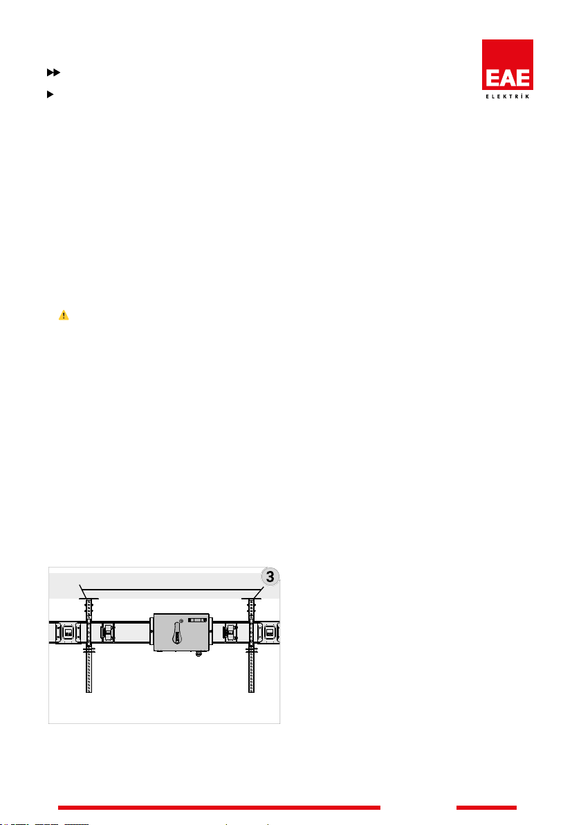
1- Installation according to the project of the
busbar system, planning and coordination with
other distribution systems (mechanical, heat,
steam, air installation etc.) is crucial.
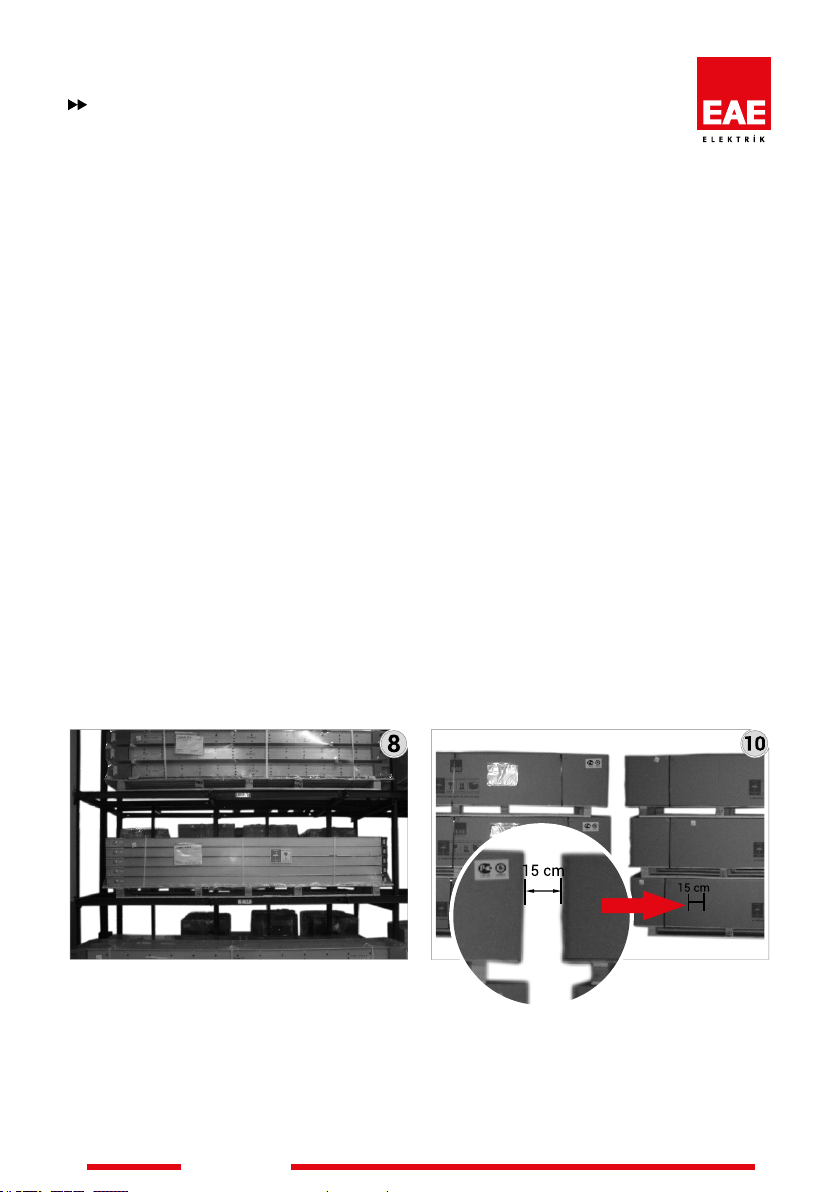
2- Operational Success of the Busbar
systems is ensured by adhering to the right
transport, proper installation and design.
Improper application may cause malfunction
of the system, personal injury and damage to
operating systems.
3- The installation, operation and maintenance
of the busbar system should only be carried out
by qualied personnel who know the dangers
associated with installation a, construction
and operation of electrical equipment for the
purposes of this manual. Additionally, this
personnel ;
* Knows the requirement of applicable electrical
laws, other laws and standards.
* Be trained and authorized to test, energize,
clean, ground, label and lock the system and
equipment suitable for occupational safety
applications.
* Be trained in the use and maintenance
of personal protective equipment such as
rubber gloves, helmets,protective goggles or
face shields and gauze-resistant clothing in
accordance with relevant work safety practices
and potential hazard levels.
* Must be trained in rst aid.
WARNING:
Dangerous voltage levels in the electrical
components may result in the hazardous injury
and death.
Installation, monitoring and maintenance must
be carried out on de-energized busbar electrical
equipment. In this way, unintentional contact to
the equipment under the energy is prevented.
must be followed all warnings and related
instructions.
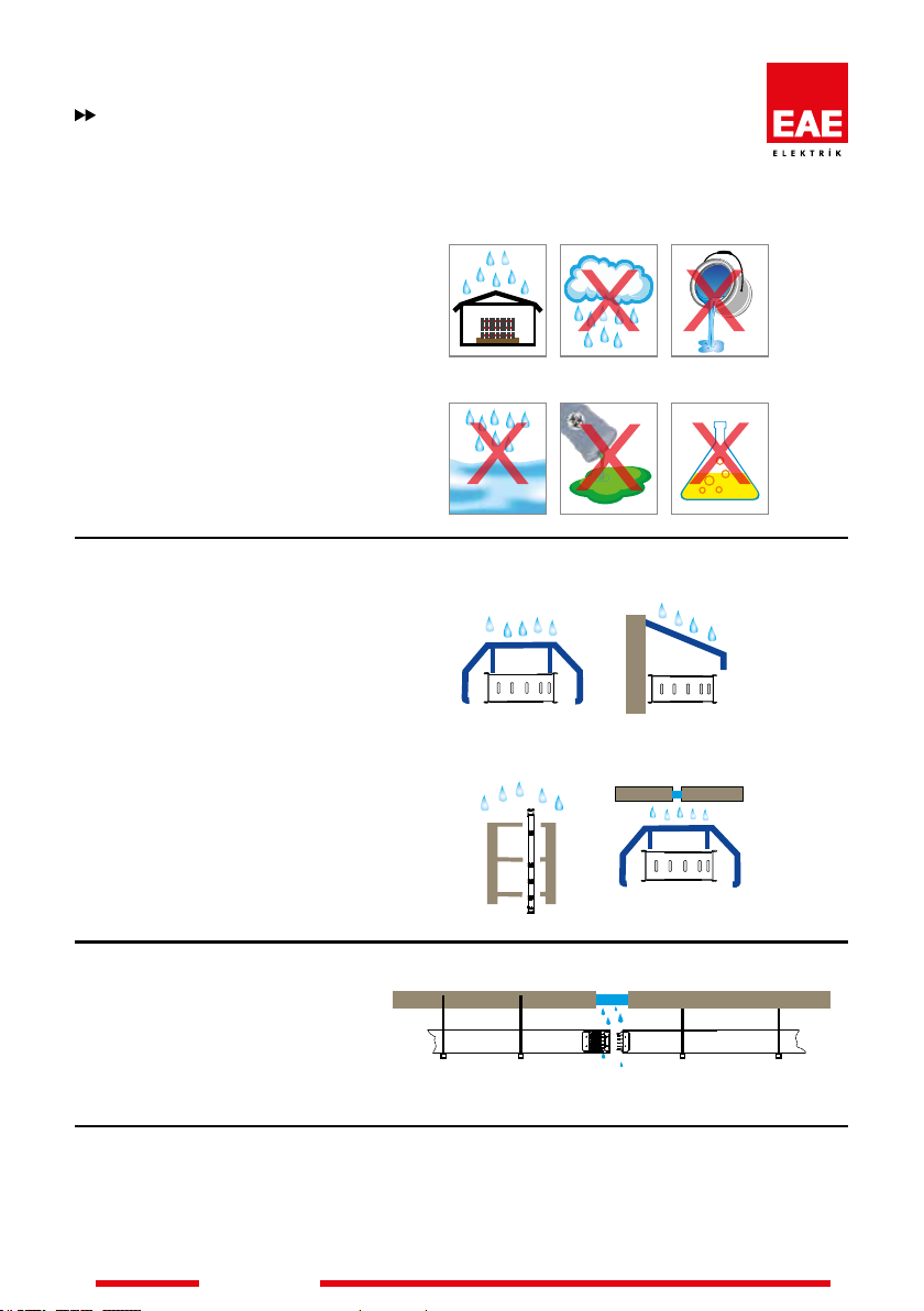
WARNING :
Operation of the busbar damaged by water or
moisture can caused damage property, serious
personal injury or death. To ensure proper
installation resistance and to ensure that the
moisture source is removed, observe the notes
in section on page 16 item 13 you receive.
General