Eagle Equipment SS7000 User manual


E
Ea
ag
gl
le
e
E
Eq
qu
ui
ip
pm
me
en
nt
t
S
SS
S7
70
00
00
0
S
Se
er
ri
ie
es
s
L
Li
if
ft
ts
s
1-800-336-2776 SS7000-1www.eagleequip.com
Table of Contents
TABLE OF CONTENTS ...................................................................................................................................................1
INTRODUCTION...............................................................................................................................................................2
WELCOME TO EAGLE EQUIPMENT........................................................................................................................2
HOW TO USE THIS MANUAL ......................................................................................................................................2
WHAT TO DO IF YOU NEED HELP............................................................................................................................2
LIFT SPECIFICATIONS..................................................................................................................................................3
SAFETY................................................................................................................................................................................3
A NOTE ABOUT HYDRAULIC FLUID........................................................................................................................3
LET’S GET STARTED .....................................................................................................................................................4
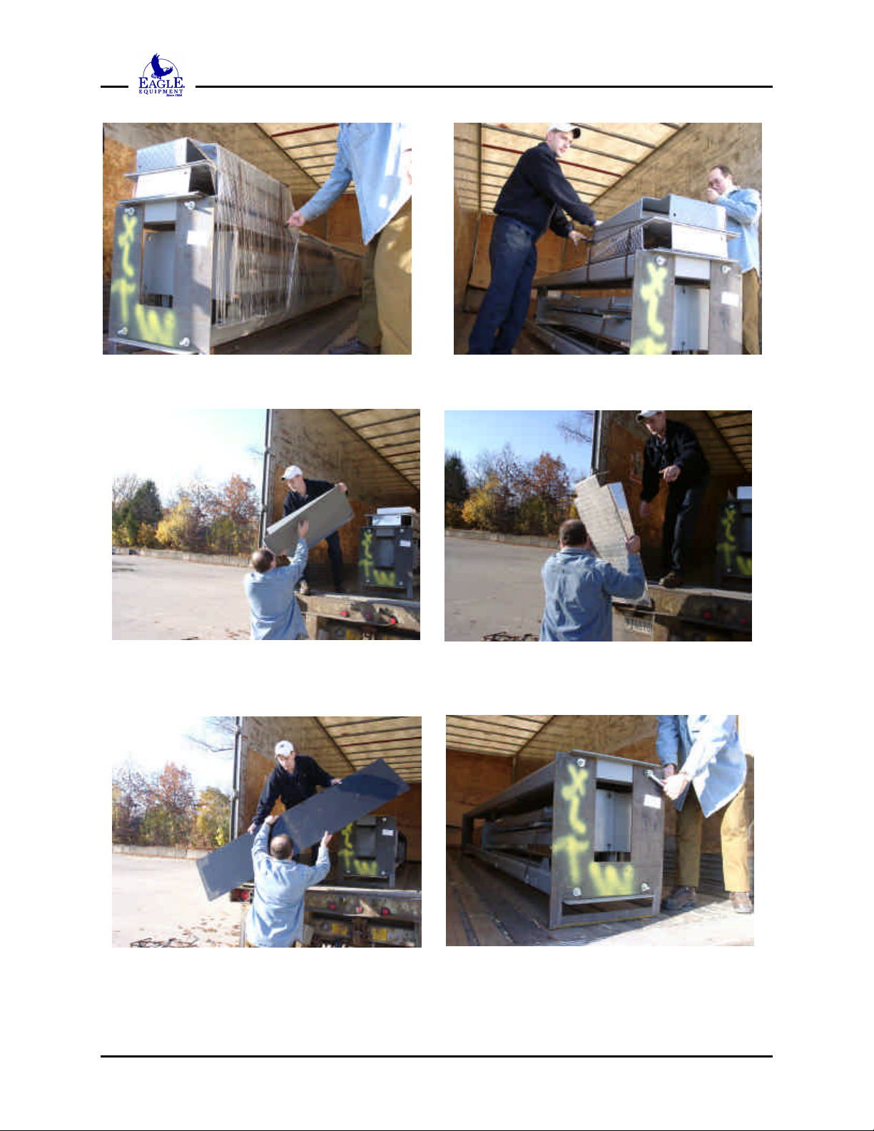
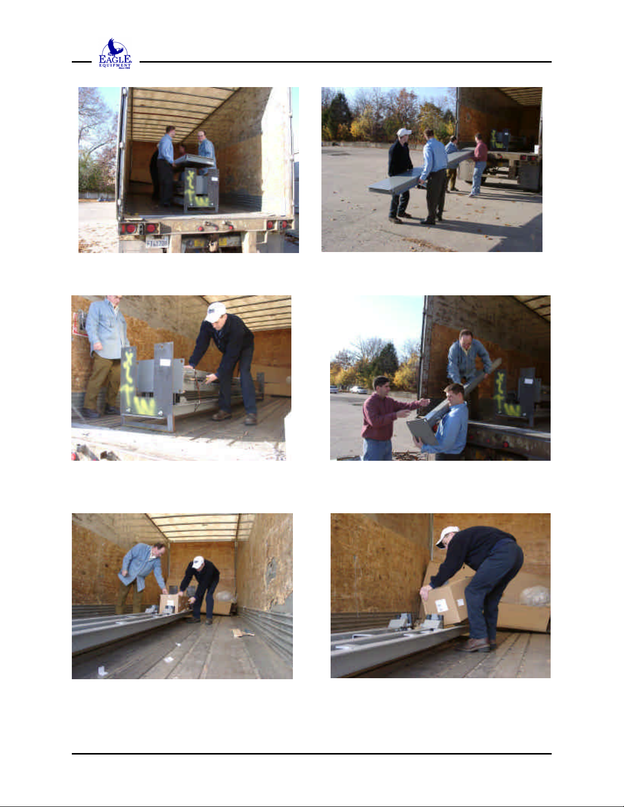
UNPACKING YOUR LIFT..............................................................................................................................................4
FIRST METHOD OF REMOVAL..................................................................................................................................5
SECOND METHOD OF REMOVAL.............................................................................................................................5
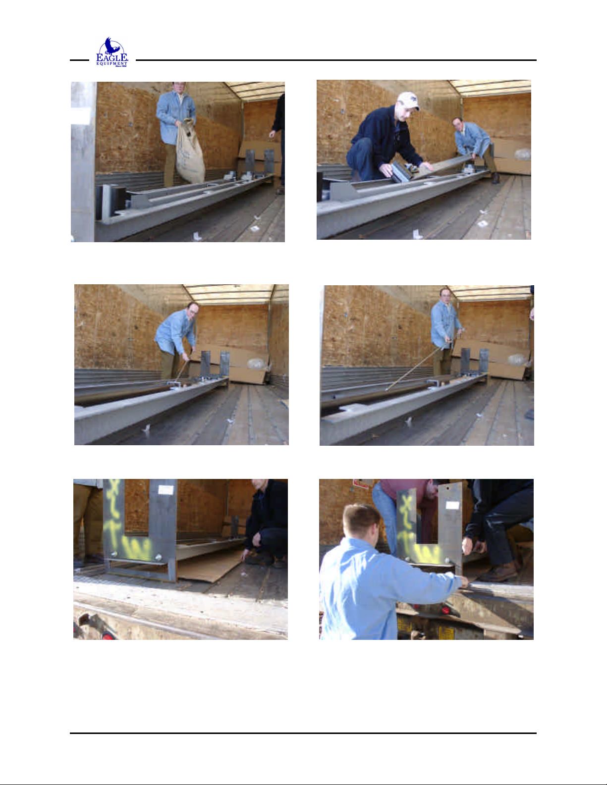
UNPACKING THE LIFT..................................................................................................................................................5
INVENTORY YOUR LIFT............................................................................................................................................11
THE MAJOR COMPONENTS OF YOUR NEW LIFT...........................................................................................13
LET’S ASSEMBLE YOUR NEW LIFT.......................................................................................................................14
ASSEMBLING YOUR LIFT..........................................................................................................................................14
POSTIONING AND ASSEMBLING THE COLUMNS ............................................................................................14
INSTALL THE TRACKS ...............................................................................................................................................18
INSTALL COLUMN TOP CAPS..................................................................................................................................20
PREPARING FOR CABLE INSTALLATION...........................................................................................................21
EXTEND THE RAM USING COMPRESSED AIR (PREFERRED METHOD).............................................................................22
EXTEND THE RAM USING A WINCH OR COME-ALONG ...................................................................................................24
MEASURING THE CABLES.........................................................................................................................................25
INSTALL THE SAFETY LOCK RODS ......................................................................................................................32
INSTALL THE HYDRAULICS.....................................................................................................................................37
ADJUSTING THE CABLES..........................................................................................................................................40
OPERATING AND MAINTAINING YOUR NEW LIFT........................................................................................41
OPERATION AND MAINTENANCE..........................................................................................................................41
INSTALL DRIVE-ON RAMPS......................................................................................................................................43
INSTALL PLASTIC SHEETS .......................................................................................................................................44
INSTALLING LIFT OPTIONS .....................................................................................................................................45
INSTALLING THE CASTER KIT ...............................................................................................................................45
APPENDIX A –PARTS LISTING ................................................................................................................................47
INDEX.................................................................................................................................................................................55

E
Ea
ag
gl
le
e
E
Eq
qu
ui
ip
pm
me
en
nt
t
S
SS
S7
70
00
00
0
S
Se
er
ri
ie
es
s
L
Li
if
ft
ts
s
1-800-336-2776 SS7000-2www.eagleequip.com
Introduction
Welcome to Eagle Equipment
Congratulations on your purchase of an Eagle Equipment 7000 series four post lift! In the pages
that follow, you will find information on how to unpack, assemble, operate, and maintain your
lift. Please take the time to read this manual thoroughly to make sure that you know what will be
required of you, your assistants, and the area in which your lift is being installed.
How To Use This Manual
We at Eagle Equipment have provided detailed step by step documentation and illustrations to
guide you through the process of installing and operating your new lift. Please take the time now
to read through this manual -a greater understanding of the procedures described here will go a
long way towards easy installation and safe, reliable operation of your lift.
This manual is arranged to guide you throughout the entire installation process from the time you
receive and unpack your lift, through assembly and operation, to the installation of accessories.
The procedures are broken down into sections as listed in the Table of Contents. The text of
each step in a procedure always follows the photographs or diagrams illustrating that step.
What To Do If You Need Help
We’ve tried to do our very best to provide complete and detailed information so that your
installation experience is free of problems; however, sometimes you just need a little help. If you
should run into any problems installing or operating your new lift, or have questions on some of
the parts, feel free to contact our service department at (800) 535-0016 Ext 113 or via email at
© EAGLE EQUIPMENT, INC.
P.O. Box 420
Chartley MA 02712-0420
SS7000 Series Installation Guide
January 2002
Manual produced by:
Tech Research Group, Inc.
2377 Pawtucket Ave
East Providence, RI 02914
Tel: (401) 434-4680
www.techresearchgroup.com

E
Ea
ag
gl
le
e
E
Eq
qu
ui
ip
pm
me
en
nt
t
S
SS
S7
70
00
00
0
S
Se
er
ri
ie
es
s
L
Li
if
ft
ts
s
1-800-336-2776 SS7000-3www.eagleequip.com
Lift Specifications
Specifications SS7000N SS7000 SS7000XLT
Maximum Capacity 7000 lbs (3180 Kg) 7000 lbs (3180 Kg) 7000 lbs (3180 Kg)
Overall Length
(without 37” ramps) 14’ 2 ½” (4.37m) 14’ 2 ½” (4.37m) 15’ 10” (4.87m)
Overall Width 102” (2.61m) 110 3/4” (2.84m) 110 3/4” (2.84m)
Height of columns-
floor to top cap
(excluding cable
stub)
82” (2.10m) 82” (2.10m) 92” (2.36m)
Maximum Wheelbase 160” (4.10m) 160” (4.10m) 166” (4.25m)
Electrical Service 12V DC, 110 V or
220 V AC as ordered 12V DC, 110 V or
220 V AC as ordered
Track Width 18” (46cm) 18” (46cm) 18” (46cm)
Rate of lift to full
height 90 seconds 90 seconds 90 seconds
Maximum clearance
between columns 92.5” (2.37m) 99” (2.53m) 99” (2.53m)
Maximum clearance
under tracks 68 1/4” (1.75m) 68 1/4” (1.75m) 77 1/2” (1.98m)
Shipping weight 1500 lbs (682Kg) 1500 lbs (682Kg) 1620 lbs (737 Kg)
Safety
Assembling your lift can be an enjoyable afternoon activity for you and your friends. Wear work
gloves and safety glasses during the installation process, and avoid alcohol when installing or
operating your lift. Ensure that nothing, especially an accident, puts a damper on your activities.
A Note about Hydraulic Fluid
Use ONLY AW-32 or ISO-32 hydraulic oil for your lift. DO NOT USE DEXRON®. Use of
Dexron®will damage the seals in the lift hydraulic system and shorten the usable life of all
hydraulic components.

E
Ea
ag
gl
le
e
E
Eq
qu
ui
ip
pm
me
en
nt
t
S
SS
S7
70
00
00
0
S
Se
er
ri
ie
es
s
L
Li
if
ft
ts
s
1-800-336-2776 SS7000-4www.eagleequip.com
Let’s Get Started
Unpacking your lift
Before you unpack the lift, take the time to make the following preparations:
Be sure you have enough help –you should have at least one assistant to help handle the largest
items since the largest component weighs approximately 300 lbs. Three assistants is preferable,
but not necessary.
Be sure you have the proper tools. You’ll need the following tools to unpack and assemble
your lift:
Tool Quantity Required
3/4” combination wrench 2
tin snips or shears 1
knife or box cutter 1
tape measure 25’ or greater 1
needlenose pliers 1
7/16” combination wrench 2
1/2” combination wrench 2
12” adjustable wrench 1
Your Eagle Equipment lift is heavy, and may pose a challenge when it comes time to take it off
the delivery truck. There are two ways of removing the packaged lift from the delivery truck

E
Ea
ag
gl
le
e
E
Eq
qu
ui
ip
pm
me
en
nt
t
S
SS
S7
70
00
00
0
S
Se
er
ri
ie
es
s
L
Li
if
ft
ts
s
1-800-336-2776 SS7000-5www.eagleequip.com
First method of removal
If you have access to a forklift, the lift may be taken from the delivery truck and unpacked close
to the installation site. The heavy end of the lift will be at the rear of the truck bed –the lift may
be picked up from this end by a forklift and removed from the truck. Remember that the
packaged lift is approximately 16 feet long. The lift may then be unpacked as described below.
Second method of removal
If no forklift is available, the lift may be unpacked on the truck and hand carried piece by piece
to the installation site. A minimum of two people capable of carrying 75 lbs each are required to
unpack the lift. Unpacking the lift on the truck should take no more than one half hour if one or
more assistants are available.
Unpack the lift as close as possible to the location you are installing it. Have scrap wood
available to support the components as they are being unpacked.
Unpacking the lift
Cut the outer banding and remove the cardboard. Don’t throw the cardboard away yet –you’ll
need it later.

E
Ea
ag
gl
le
e
E
Eq
qu
ui
ip
pm
me
en
nt
t
S
SS
S7
70
00
00
0
S
Se
er
ri
ie
es
s
L
Li
if
ft
ts
s
1-800-336-2776 SS7000-6www.eagleequip.com
Remove the plastic wrap, then cut the banding from the drive-on ramps.
Remove the two drive-on ramps from the packed lift, and place them out of the way –you won’t
need them until the lift is ready for use. (the aluminum ramps shown here are optional)
Remove the two plastic drip shields and set aside. Unbolt the shipping brackets from both ends
of the offside track using two ¾” wrenches.

E
Ea
ag
gl
le
e
E
Eq
qu
ui
ip
pm
me
en
nt
t
S
SS
S7
70
00
00
0
S
Se
er
ri
ie
es
s
L
Li
if
ft
ts
s
1-800-336-2776 SS7000-7www.eagleequip.com
Remove the offside track. This is a two person end lift –be sure you have enough help. Place
the offside track out of the way, but close to the installation site.
Cut the banding from the columns and then remove the columns –don’t stand them up or lean
them on anything. Lay them flat and out of the way.
Cut the banding from the cardboard parts boxes and remove the parts boxes. The larger box
contains the hydraulic power unit; the smaller box contains hardware.

E
Ea
ag
gl
le
e
E
Eq
qu
ui
ip
pm
me
en
nt
t
S
SS
S7
70
00
00
0
S
Se
er
ri
ie
es
s
L
Li
if
ft
ts
s
1-800-336-2776 SS7000-8www.eagleequip.com
Remove the burlap bag containing the cables and end stops. Remove the two cross rails. The
cross rails may need to be rolled out of the mainside track in order to free them.
Remove two 1/4” diameter linkage rods, then remove the 1/2” diameter safety lock rod.
Place the packing cardboard you put aside under the mainside track –you’ll need at least two
people to raise each end of the mainside track. Slide the mainside track with shipping bracket
attached over the edge of the truck bed and onto the packing cardboard.

E
Ea
ag
gl
le
e
E
Eq
qu
ui
ip
pm
me
en
nt
t
S
SS
S7
70
00
00
0
S
Se
er
ri
ie
es
s
L
Li
if
ft
ts
s
1-800-336-2776 SS7000-9www.eagleequip.com
Remove the bolts from the front shipping bracket and remove the bracket. The bracket is heavy
–do not let the bracket fall when removing the bolts.Discard the brackets after removal.
Pull the end of the mainside track out of the truck and onto the ground. The mainside track
weighs in excess of 300 lbs. –you need at least two people capable of lifting 75 lbs each to lift
the track end. The edges may be sharp –wear heavy work gloves.
Remove the two bolts holding the rear shipping bracket to the mainside track, and remove the
bracket. Discard the shipping bracket.

E
Ea
ag
gl
le
e
E
Eq
qu
ui
ip
pm
me
en
nt
t
S
SS
S7
70
00
00
0
S
Se
er
ri
ie
es
s
L
Li
if
ft
ts
s
1-800-336-2776 SS7000-10 www.eagleequip.com
Remove the mainside track from the delivery truck. The mainside track weighs more than 300
pounds –walk it into location end by end if there’s just you and an assistant, or carry it if you
have four people available.
Remove the power unit from the large cardboard box –cut straps and remove all packing
materials from power unit. Remove any remaining packing materials and straps from the
mainside track. Open the small cardboard parts box , empty the burlap bag, and arrange the
components of your lift so that every part is visible and easy to identify. Make sure you have
your packing list.
Inventory your lift at this time. Pay attention to optional components your may have ordered
with your lift. Some parts come in different lengths, depending on the model -check the part
you have, and then double check that you have the right part for the right model.

E
Ea
ag
gl
le
e
E
Eq
qu
ui
ip
pm
me
en
nt
t
S
SS
S7
70
00
00
0
S
Se
er
ri
ie
es
s
L
Li
if
ft
ts
s
1-800-336-2776 SS7000-11 www.eagleequip.com
Inventory your lift
Item Quantity
SS7000N SS7000 SS7000XLT
Mainside Track w/ cylinder 111
Offside Track 111
Cross Bar 102” 2
Cross Bar 108 ½” 22
Rod, 1/4” x 79” 2
Rod, 1/4” x 82 ½” 22
Rod, 1/2” x 126” 111
Rod, Bent, 1/2” x 50” 11
Rod, Bent, 1/2” x 70” 1
Ramp Clips 444
Cable, 8’ 4” 1
Cable, 13’ 1
Cable, 21’ 3” 1
Cable, 25’ 11” 1
Cable, 8’ 7” 1
Cable, 13’ 3” 1
Cable, 21’ 5 ½” 1
Cable, 26’ 1 ½” 1
Cable, 9’ 5” 1
Cable, 14’ 1” 1
Cable, 23’ 11” 1
Cable, 28’ 7” 1
Column, R marking 222
Column, L marking 222
Top Cap, R marking 222
Top Cap, L marking 222
Sheet, Plastic, 18” x 80” 222
Power Unit 111
Ramp, Drive-on 222
Bolt Box 111
The Bolt Box contains:
Item SS7000N SS7000 SS7000XLT
Cable Retainer (thin plate) 111
Cable Holder (thick plate) 111
Rod, 1/4” x 6” 2
Rod, 1/4” x 9 22
Bolt, 1/2” x 4” 888
Bolt, 1/2” x 7” 444
Coupler, 1/2” 111
Hose, Track to Cylinder, 64”1
Hose, Track to Cylinder, 82” 11
Hose, Power unit to Track, 71” 111
Hardware Bags (A, B, C, D, E) 1 each 1 each 1 each

E
Ea
ag
gl
le
e
E
Eq
qu
ui
ip
pm
me
en
nt
t
S
SS
S7
70
00
00
0
S
Se
er
ri
ie
es
s
L
Li
if
ft
ts
s
1-800-336-2776 SS7000-12 www.eagleequip.com
Bag A contains:
Item Quantity
Bolt, 1/2” x 1 1/4” 4
Washer, 1/2” 16
Nut, Nylon Insert, 1/2” 8
Washer, Flat, 3/4” 4
Nut, Cable, 3/4” 4
Clip, Plastic 2
Tie Wrap 2
Bag B contains:
Item Quantity
Heim End 8
Nut, Nylon Insert, 1/4” 8
Nut, Lock, 1/4” 8
Bolt, 1/4” x 1 3/4” 4
Bolt, 1/4” x 1 1/4” 4
Spacer 2
Nut, 1/2” 2
Knob, Black 1
Bag C contains:
Item Quantity
Washer, Flat, 1/2” 16
Nut, 1/2” 8
Eyebolt, 1/4” 2
Washer, Flat, 1/4” 4
Nut, 1/4” 4
Bag D contains:
Item Quantity
90oFitting w/ Nut 1
90oFitting w/ O-Ring 1
90oFitting w/o O-Ring 1
Vent Fitting, 3/8” NPT 1
Nut, Nylon Insert, 1” 1
Washer, 1” 1
Bag E contains:
Item Quantity
Bolt, 5/16” x 1” 4
Nut, Nylon Insert, 5/16” 4
Nut, 5/16” 4

E
Ea
ag
gl
le
e
E
Eq
qu
ui
ip
pm
me
en
nt
t
S
SS
S7
70
00
00
0
S
Se
er
ri
ie
es
s
L
Li
if
ft
ts
s
1-800-336-2776 SS7000-13 www.eagleequip.com
The Major Components Of
Your New Lift
Before you get started assembling your new lift, let’s take a moment and become familiar with
some of the major components. Becoming familiar with the major components of the lift will
make the assembly task quicker and easier.
Major Components of the SS7000 Series Lift
Corner
column
Top cap
Ramp clip
Safety lock
blocks
Mainside track
Offside track
Power unit
with hydraulic
fluid reservoir
Hydraulic ram
(under track)
Safety lock
Safety lock
release handle
Cross
tube
End stop
Drive-up
Ramp

E
Ea
ag
gl
le
e
E
Eq
qu
ui
ip
pm
me
en
nt
t
S
SS
S7
70
00
00
0
S
Se
er
ri
ie
es
s
L
Li
if
ft
ts
s
1-800-336-2776 SS7000-14 www.eagleequip.com
Let’s Assemble Your New Lift
Assembling Your Lift
Now that you have your lift unpacked close to the installation site, you may begin assembly.
While most assembly procedures may be done by one or two people, remember that you are
going to have to lift the heavy components into position –and you’ll still need at least two
people capable of carrying 75 pounds each to do so.
In the following assembly sequence, an older style of column was used to clearly illustrate the
safety stops. Current production lift columns have column stop blocks with a safety cover
installed. This safety feature lessens the risk of catching a finger or clothing in the stop blocks.
Positioning and Assembling the Columns
Position the columns according to the floor plan on the following page. Lay down rear columns
(L and R designations or labels do not indicate left or right positions during layout. Check your
lift floor plan before positioning the columns, and then check it again after you’ve positioned
them –the assembled columns are heavy and difficult to move.)

E
Ea
ag
gl
le
e
E
Eq
qu
ui
ip
pm
me
en
nt
t
S
SS
S7
70
00
00
0
S
Se
er
ri
ie
es
s
L
Li
if
ft
ts
s
1-800-336-2776 SS7000-15 www.eagleequip.com
Floor Plan For Initial Column Positioning

E
Ea
ag
gl
le
e
E
Eq
qu
ui
ip
pm
me
en
nt
t
S
SS
S7
70
00
00
0
S
Se
er
ri
ie
es
s
L
Li
if
ft
ts
s
1-800-336-2776 SS7000-16 www.eagleequip.com
Position the cross rail at the top of the two columns. Install the cross rail in the column tops by
inserting the plastic guide blocks in the column channel (Make sure the safety locks are
positioned with bevel side up, and with safety locks facing towards the outside of the lift).
Using two people, lift the safety locks and pull the cross rail down evenly to the lowest stop
block. Keep your fingers out of the track –the safety locks aren’t heavily loaded, but you can
still get your fingers pinched.
Plastic Guide Block
Safety Lock

E
Ea
ag
gl
le
e
E
Eq
qu
ui
ip
pm
me
en
nt
t
S
SS
S7
70
00
00
0
S
Se
er
ri
ie
es
s
L
Li
if
ft
ts
s
1-800-336-2776 SS7000-17 www.eagleequip.com
Repeat the procedure for the remaining columns and cross rail. When you have completed
assembling the columns and cross rails and are ready to go on to the next step, stand the
assembled columns up in the positions indicated on the floor plan. Position the two column
assemblies 170 1/2” apart for the SS7000N and the SS7000; 190” apart for the SS7000XLT.
Measure the distance from the outside of the column baseplates, so that the measurement
includes the column baseplates.
170 ½” –SS7000N and SS7000
190” –SS7000XLT
Column
Baseplate
Column
Baseplate

E
Ea
ag
gl
le
e
E
Eq
qu
ui
ip
pm
me
en
nt
t
S
SS
S7
70
00
00
0
S
Se
er
ri
ie
es
s
L
Li
if
ft
ts
s
1-800-336-2776 SS7000-18 www.eagleequip.com
Install the Tracks
At this time you have to decide where you want to place the power unit –your lift controls are on
it. The power unit can be mounted to either column marked “R”, with the power unit mounting
bracket placed at the driver’s side front or passenger’s side rear. The mainside track will be
installed on the same side, with the power cylinder closest to where you will mount the power
unit. Position the mainside track and the offside track outside of the columns.
With an assistant, pick up and place one end of the mainside track in location on the crossrail,
and then pick up and place the other end on the opposite crossrail (if you have three assistants,
place both ends at the same time). Use a large screwdriver or aligning punch to align the
mounting holes in the cross rails with the mounting holes in the track.
WARNING!
Do not leave the tracks unbolted –install the mounting bolts immediately!
Power Unit
Mounting
Bracket
Mounting Holes
This manual suits for next models
2
Table of contents
Other Eagle Equipment Lifting System manuals