Eagle Eye Power Solutions LB-60-100D User manual

LB-60-100D
LOAD BANK
MANUAL CONTAINS
OPERATING INSTRUCTIONS
PARTS LIST
WIRING DIAGRAMS
SERVICE INSTRUCTIONS
EAGLE EYE POWER SOLUTIONS, LLC
4031 W Kiehnau Ave
Milwaukee, WI 53209
877-805-3377
This load bank is manufactured and protected under U. S. Patent number 4,445,047

Eagle Eye Power Solutions, LLC | 1-877-805-3377 | www.eepowersolutions.com
THIS LOAD BANK IS DESIGNED FOR THE TESTING AND SERVICING 480/208V 60HZ
POWER UNITS. THESE UNITS HAVE THE POTENTIAL OF DELIVERING A LETHAL
SHOCK. THIS LOAD BANK SHOULD BE USED ONLY BY TRAINED AND QUALIFIED
PERSONNEL. THIS LOAD BANK IS DESIGNED FOR TEMPORARY USE ONLY. THE
LOAD RESISTORS ARE ENERGIZED WHEN THE RATE SWITCH IS OFF, THEREFORE
DO NOT INSERT ANY OBJECTS IN THE GRILL ASSEMBLY. DO NOT BLOCK THE AIR
FLOW OR USE IF THE AIR FLOW IS REVERSED.

Eagle Eye Power Solutions, LLC | 1-877-805-3377 | www.eepowersolutions.com
TABLE OF CONTENTS
SUBJECT
SECTION
PAGE
DESCRIPTION
PURPOSE OF LOAD BANK
1 - 1
1
RATING OF LOAD BANK
1 - 2
1
LOAD BANK DESCRIPTION
FIGURE 1 - 1
1 - 3
1
CONTROL PANEL LAYOUT
FIGURE 1 - 2
1
2
CONTROL DESCRIPTION
1 - 4
3
OPERATION
TESTING 120VAC SINGLE PHASE
2
1
TESTING 240VAC SINGLE PHASE
2
3
TESTING 208VAC THREE PHASE
2
5
TESTING 240VAC THREE PHASE
2
7
TESTING 480VAC THREE PHASE
2
9
PARTS
PARTS INFORMATION
3
1
CONTROL PANEL PARTS LAYOUT
FIGURE 3 - 1
3
2
CONTROL PANEL PARTS LIST
3
3
INTERIOR PARTS LAYOUT
FIGURE 3 - 2
3
4
INTERIOR PARTS LIST
3
5
FAN PANEL PARTS LAYOUT
FIGURE 3 - 3
3
6
FAN PANEL PARTS LIST
3
7
VENDOR LIST
3
8
SERVICING
GENERAL SERVICING
4 - 1
1
REPLACING FAN
FIGURE 4 - 1
4 - 2
2
WIRING DIAGRAMS
INTERIOR W IRING
FIGURE 5 - 1
5
1
FAN PANEL WIRING
FIGURE 5 - 2
5
3
SCHEMATIC DIAGRAM
FIGURE 5 - 3
5
5

Eagle Eye Power Solutions, LLC | 1-877-805-3377 | www.eepowersolutions.com
--------
1-1
PURPOSE OF LOAD BANK: The LB-60-100D is a portable load bank designed to be used for field
servicing and testing 60HZ generators and UPS systems. It can be used for checking cables after they
have been replaced or repaired. The load bank can also be shipped to different locations using the carrying
case.
1-2
RATING OF LOAD BANK: The LB-60-100D is rated at 100KW full load when the input voltage is
480VAC and 80 KW when the input voltage is 208VAC with all five load steps turned on. The load steps are
12.5KW, 12.5KW, 25KW, 25KW and 25KW at 480VAC, 5KW or 10KW, 10KW, 20KW, 20KW, 20KW at
208VAC. All steps are continuous. This unit can be used for 60HZ and 400HZ testing.
1-3
LOAD BANK DESCRIPTION: The load bank is uses a 120VAC power source to operate other than the
power being tested. The different sides of the load bank are shown in fig. 1-1. The air enters the right side
(fan side) and exits the left side.
<<<< AIR FLOW <<<<
LEFT SIDE------------------------------------------------------------------------------------------ RIGHT SIDE (FAN SIDE)
FIGURE 1-1
LENGTH 22 IN.
WIDTH 8 IN.
HEIGHT 21 IN.
WEIGH 60 LBS.
CONTROL PANEL PARTS

Eagle Eye Power Solutions, LLC | 1-877-805-3377 | www.eepowersolutions.com
@208V
LB-60-100D
100KW AT 480 VAC
80KW AT 208VAC
60KW CONTINUOUS
AT 208VAC
L1 1 1 5.0
L2 1 1 5.0
L3 1 1 5.0
DIGITAL METER
480VAC
L1 L2 L3 POWER
INDICATOR
LIGHTS
MAIN
SWITCH OFF MAIN
208VAC
USD PORT
12.5KW
12.5KW
25KW 25KW 25KW
RATE
SWITCHES
LOAD 10KW
10KW
20KW 20KW
20KW
OFF 5KW
OFF
A B C N
METER TEST JACKS
L2 POWER
CONNECTORS
FIGURE 1-2 L1 L3
N

Eagle Eye Power Solutions, LLC | 1-877-805-3377 | www.eepowersolutions.com
1-4
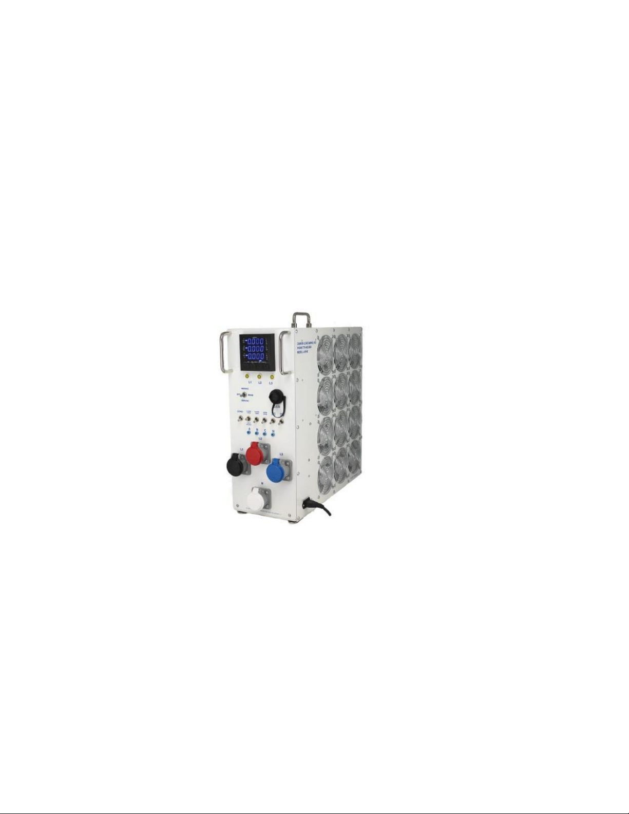
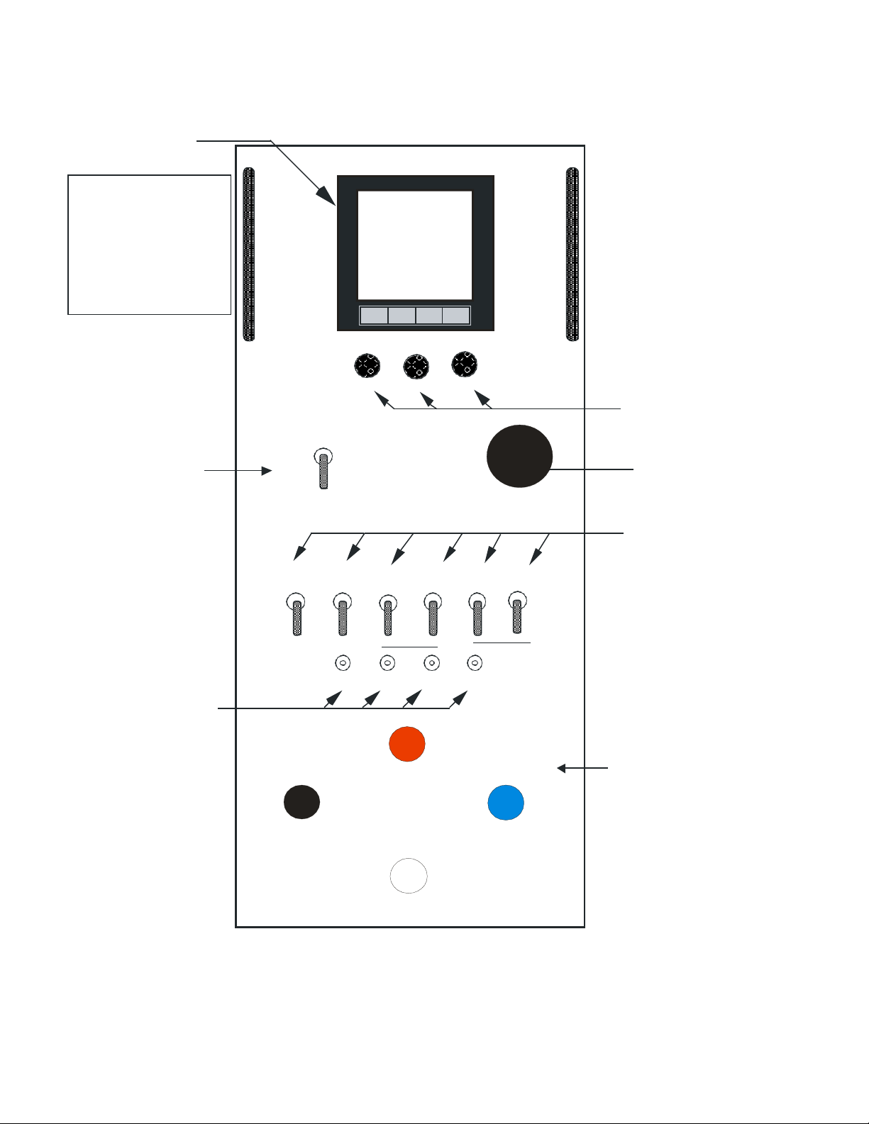
CONTROL DESCRIPTION: The following is a description of the controls on the control panel (see figure
1-2 on page 2.
DIGITAL MULTIMETER - A three phase meter used to measure, Phase Voltage (V),Phase to Neutral (V),
Frequency (Hz),Phase Current (I),Neutral Current (I),Active Power (W),Reactive Power (Var),
Apparent Power (VA), Power Factor ( P.F.), Active Energy (W.h), Reactive Energy Var.h), Instantaneous Demand
Amp, Instantaneous Demand Active Power, Instantaneous Demand Apparent Power,
Maximum Demand Amps, Maximum Demand Active Power, Maximum Demand Apparent Power.
The meter should read approximately 208 volts line to line or 480 volts line to line.
RATE SWITCHES - Switch used to select the desired rate on the load bank. The rates are as follows:
480VAC 208VAC
1.
12.5 KW balanced load 1. 5 KW or 10 KW balanced load
2.
12.5 KW balanced load 2. 10 KW balanced load
3.
25 KW balanced load 3. 20 KW balanced load
4.
25 KW balanced load 4. 20 KW balanced load
5.
25 KW balanced load 5. 20 KW balanced load
POWER INDICATOR LIGHTS - These lights will light to indicate power on A, B, and C phase. All three lights
should be on when testing three phase circuits.
METER TEST JACKS - This provides a place to connect an external meter. There is a test jack for each cable
pin.
POWER RECEPTACLE - The power cable from the equipment to be tested is plugged into the load bank
through the receptacle.
USB PORT- For monitoring and logging of meter data. Programs are included on USB jump drive located on
handle of load bank.
120 VOLT POWER RECEPTACLE - A power cable is provided to plug the unit into a 120VAC outlet.
(Not shown on drawing)

Eagle Eye Power Solutions, LLC | 1-877-805-3377 | www.eepowersolutions.com
OPERATION
TESTING 120VAC SINGLE PHASE
2-1
SETTING UP THE LOAD BANK - Place the load bank in an area free from fuel, oil, or any other flammable
substance. The load bank should be positioned so that any strong wind or air currents will flow with the air
flow of the load bank.
2-2
APPLYING POWER - The load bank should be connected to the power unit to be tested with an output of
120VAC single phase. Make sure that the power unit is off before connecting the cable to the load bank. Use
L1 (Black), L2 (Red) and N (White), when testing single phase circuits. L1 should be connected to the line out,
L2 should be connected to neutral and the N cable should be connected to the ground of the unit being tested.
Plug the power cable plug in to the load bank. The meter switch should be in the L1-L2 position. Turn on the
output of the power unit.
2-3
CHECKING THE POWER - check the following:
A.
The amber light, “A” should be on.
B.
The VOLTS should read 120VAC on “A” phase.
C.
The FREQUENCY should read approximately 60HZ.
D.
The AMPS should read 0A.
2-4
APPLYING THE LOAD - If the above steps checked OK, turn on the main switch to 208VAC. The fans
should start up and the airflow should be as indicated by the airflow arrow. Next turn on the load switch. Add
the load desired with the rate switch.
A.
Step 1 is 1.7KW
B.
Step 2 is 1.7KW
C.
Step 3 is 3.3KW
D.
Step 4 is 3.3KW
E.
Step 5 is 3.3KW
Total load at 120VAC is 13.3KW.
Check to see that the voltage and frequency does not drop beyond acceptable limits under load.
2-5
SHUTTING DOWN - Turn the load switch and rate switches to the off position and allow the load bank to
cool down before turning the main switch to off. Turn the power unit off and disconnect the power cable plug.

Eagle Eye Power Solutions, LLC | 1-877-805-3377 | www.eepowersolutions.com
OPERATION
TESTING 240VAC SINGLE PHASE
2-1
SETTING UP THE LOAD BANK - Place the load bank in an area free from fuel, oil, or any other flammable
substance. The load bank should be positioned so that any strong wind or air currents will flow with the air
flow of the load bank.
2-2
APPLYING POWER - The load bank should be connected to the power unit to be tested with an output of
240VAC single phase. Make sure that the power unit is off before connecting the cable to the load bank. Use
L1 (Black), L2 (Red) and N (White) when testing 240VAC single phase circuits. Plug the power cable plug in to
the load bank and connect the L1 cable to L1 on the power unit, the L2 cable to L2 on the power unit and N to
the ground on the power unit. The meter switch should be in the L1-L2 position. Turn on the output of the
power unit.
2-3
CHECKING THE POWER - check the following:
A.
The amber light, “A” and “B” should be on.
B.
The VOLTS should read 240VAC on “A” and “B” phase.
C.
The FREQUENCY should read approximately 60HZ.
D.
The AMPS should read 0A.
2-4
APPLYING THE LOAD - If the above steps checked OK, turn the main switch to 208VAC. The fans
should start up and the airflow should be as indicated by the airflow arrow. Next turn on load switch. Add the
load desired with the rate switch.
A.
Step 1 is 6.6KW
B.
Step 2 is 6.6KW
C.
Step 3 is 13.2KW
D.
Step 4 is 13.2KW
E.
Step 5 is 13.2KW
Total load at 240Vac single phase is 52.8KW
Check to see that the voltage and frequency does not drop beyond acceptable limits under load.
2-5
SHUTTING DOWN -Turn the load and rate switches to off, allow the load bank to cool down before turning
the main switch to off. Turn the power unit off and disconnect the power cable plug.

Eagle Eye Power Solutions, LLC | 1-877-805-3377 | www.eepowersolutions.com
OPERATION
TESTING 208VAC THREE PHASE
2-1
SETTING UP THE LOAD BANK - Place the load bank in an area free from fuel, oil, or any other flammable
substance. The load bank should be positioned so that any strong wind or air currents will flow with the air
flow of the load bank.
2-2
APPLYING POWER - The load bank should be connected to the power unit to be tested with an output of
208VAC 3 phase, plug in the 120VAC power cord. Make sure that the main switch and the load switch is set
to off before connecting the cable to the load bank. Use L1 (Black), L2 (Red), L3 (Blue) and N (White), when
testing 208VAC 3 phase circuits. Plug the power cable plug in to the load bank. Turn on the output of the
power unit.
2-3
CHECKING THE POWER - check the following:
A.
The amber light, “A”, “B”,”C” should be on.
B.
The VOLTS should read 208VAC.
C.
The FREQUENCY should read approximately 60HZ.
D.
The AMPS should read 0A.
2-4
APPLYING THE LOAD - If the above steps checked OK, turn the main switch to 208VAC. The fans should
start up and the airflow should be as indicated by the airflow arrow. Next turn on the load switch. Add the load
desired with the rate switch.
A.
Step 1 is 10KW UP or 5KW DOWN
B.
Step 2 is 10KW
C.
Step 3 is 20KW
D.
Step 4 is 20KW
E.
Step 5 is 20KW
Check to see that the voltage and frequency does not drop beyond acceptable limits under load. Return the
rate switch to the off position.
2-5
SHUTTING DOWN - Return the load and rate switches to the off position and, allow the load bank to cool
down before turning the power unit off. Turn the power unit off and disconnect the power cable plug.

Eagle Eye Power Solutions, LLC | 1-877-805-3377 | www.eepowersolutions.com
OPERATION
TESTING 240VAC THREE PHASE
2-1
SETTING UP THE LOAD BANK - Place the load bank in an area free from fuel, oil, or any other flammable
substance. The load bank should be positioned so that any strong wind or air currents will flow with the air
flow of the load bank.
2-2
APPLYING POWER - The load bank should be connected to the power unit to be tested with an output of
240VAC 3 phase, plug in the 120VAC power cord. Make sure that the main switch and the load switch is set
to off before connecting the cable to the load bank. Use L1 (Black), L2 (Red), L3 (Blue) and N (White), when
testing 240VAC 3 phase circuits. Plug the power cable plug in to the load bank. Turn on the output of the
power unit.
2-3
CHECKING THE POWER - check the following:
A.
The amber light, “A”, “B”,”C” should be on.
B.
The VOLTS should read 240VAC.
C.
The FREQUENCY should read approximately 60HZ.
D.
The AMPS should read 0A.
2-4
APPLYING THE LOAD - If the above steps checked OK, turn the main switch to 208VAC. The fans should
start up and the airflow should be as indicated by the airflow arrow. Next turn on the load switch. Add the load
desired with the rate switch.
A. Step 1 is
12.5
KW
B. Step 2 is
12.5
KW
C. Step 3 is
25
KW
D. Step 4 is
25
KW
E. Step 5 is
25
KW
Check to see that the voltage and frequency does not drop beyond acceptable limits under load.
2-5
SHUTTING DOWN - Return the load and rate switches to the off position and, allow the load bank to cool
down before turning the power unit off. Turn the power unit off and disconnect the power cable plug.

Eagle Eye Power Solutions, LLC | 1-877-805-3377 | www.eepowersolutions.com
OPERATION
TESTING 480VAC THREE PHASE
2-1
SETTING UP THE LOAD BANK - Place the load bank in an area free from fuel, oil, or any other flammable
substance. The load bank should be positioned so that any strong wind or air currents will flow with the air
flow of the load bank.
2-2
APPLYING POWER - The load bank should be connected to the power unit to be tested with an output of
480VAC 3 phase, plug in the 120VAC power cord. Make sure that the main switch and the load switch is set
to off before connecting the cable to the load bank. Use L1 (Black), L2 (Red), L3 (Blue) and N (White), when
testing 480VAC 3 phase circuits. Plug the power cable plug in to the load bank. Turn on the output of the
power unit.
2-3
CHECKING THE POWER - check the following:
A.
The amber light, “A”, “B”,”C” should be on.
B.
The VOLTS should read 480VAC.
C.
The FREQUENCY should read approximately 60HZ.
D.
The AMPS should read 0A.
2-4
APPLYING THE LOAD - If the above steps checked OK, turn the main switch to 480VAC. The fans should
start up and the airflow should be as indicated by the airflow arrow. Next turn on the load switch. Add the load
desired with the rate switch.
A. Step 1 is
12.5
KW
B. Step 2 is
12.5
KW
C. Step 3 is
25
KW
D. Step 4 is
25
KW
E. Step 5 is
25
KW
Check to see that the voltage and frequency does not drop beyond acceptable limits under load.
2-5
SHUTTING DOWN -Return the load and rate switches to the off position and allow the load bank to cool
down before turning the power unit off. Turn the power unit off and disconnect the power cable plug.

Eagle Eye Power Solutions, LLC | 1-877-805-3377 | www.eepowersolutions.com
PARTS INFORMATION
The following pages list the parts used in the load bank. All of the major parts are shown. Wire, screws, bolts,
and small miscellaneous hardware are not listed. Parts that are purchased from a vendor will show a vendor
name. These names refer to the vendor list is on page 8.
A part number can be found by first locating the part on a drawing. After finding the part use the number to refer
to the parts list on the opposite page. Each part will have a drawing number, Load Banks part number,
description and the number used for each load bank.
Parts should be ordered from the address below giving the machine model number, part number and the
description.

Eagle Eye Power Solutions, LLC | 1-877-805-3377 | www.eepowersolutions.com
CONTROL PANEL PARTS
FIGURE 3-1
DRAWING
NUMBER
PART
NUMBER
DESCRIPTION
VENDOR NO.
NUMBER
USED
1
MR-D60
0 - 600V DIGITAL METER
1
2
HD-25
HANDLE
2
3
LT-25
250VAC AMBER LIGHT
3
4
SW-69
TOGGLE SWITCH DPDT, DELAY
1
5
SW-22
TOGGLE SWITCH DPST
6
6
TP-10
TEST PIN
4
7
PL-08
USB PORT
1
8
CA-02
RED MALE CAM-LOC
1
9
CA-12
BLUE MALE CAM-LOC
1
10
CA-05
WHITE MALE CAM-LOC
1
11
CA-00
BLACK MALE CAM-LOC
1

Eagle Eye Power Solutions, LLC | 1-877-805-3377 | www.eepowersolutions.com
INTERIOR PARTS
FIGURE 3-2
DRAWING
NUMBER
PART
NUMBER
DESCRIPTION
VENDOR NO.
NUMBER
USED
1
HD-10
FOLDING HANDLE
1
2
BX-27D
20" X 21" X 8" ALUM BOX
1
3
RC-14
12KΩ, 11W RESISTOR
1
4
TM-13
TERMINAL STRIP 13 POS
1
5
FS-62
250 FUSE, 600V
3
6
FT-10
GLIDES
8
7
LR-25
25Ω RESISTOR
48
8
RY-35
RELAY, 24VDC, 30A, MAGNACRAFT
16
9
RD-19
200V, 5W ZENER DIODE
2
10
RY-21
RELAY, 120VAC, 2PDT, 10A
MIDTEX 25862T200
1
11
SW-11
AIR FLOW SWITCH
1
12
CT-15
250:5 CURRENT TRANSFORMER
3
*
GL-20
RESISTOR GRILL
1

Eagle Eye Power Solutions, LLC | 1-877-805-3377 | www.eepowersolutions.com
FAN PANEL PARTS
DRAWING
PART
FIGURE 3-3
DESCRIPTION
NUMBER
NUMBER
NUMBER
VENDOR NO.
USED
1
FS-11
FUSE 10A GLASS
1
2
TM-20
8 POSITION TERMINAL STRIP
V-BEAU PRODUCTS (78008)
1
3
PS-30
30VDC 400W POWER SUPPLY
RICHARDSON (NL3271)
1
4
FP-57
ALUM. FAN PANEL
1
5
GL-10
FAN GRILL CHROME
V-MERRILL (B-22662)
12
6
FN-25
24VDC FAN
EBM (W2G110-AK43-31)
12
7
TS-15
THERMAL SWITCH
GEMLINE (L-155)
1
8
SW-12
TILT SWITCH
1
9
AC-12
120VAC PLUG CONNECTION
1

Eagle Eye Power Solutions, LLC | 1-877-805-3377 | www.eepowersolutions.com
VENDOR LIST
The following is a list of vendors for parts shown in the parts list.
VENDOR
Anderson Power Products
145 Newton St.
Boston MA. 02135
Allied Electronics, Inc.
3425 Corporate Way, Suite A
Duluth, Ga. 30136
Bussmann Manufacturing
Distributed by Allied
Control Design Supply
1939-F Parker CT
Stone Mountain, GA. 30087
Cutler-Hammer
Distributed by Peerless
EBM Industries, Inc.
Distributed by Peerless
E.F. Johnson
Distributed by Peerless
Electric Supply Co.
433 Bishop St.
Atlanta, Ga. 30325
Gemline Products, Inc.
12472 Edison Way
Garden Grove, Ca. 92641
Merrill Manufacturing Corpation
236 South Genesee Street
Merrill, WI. 54452
Peerless Radio Corporation
3101 towercreek Pkwy, Suite 590
Atlanta, GA. 30339
Syrelec Electronics Corp.
Distributed by Control Design
Vemaline Products
333 Strawberry Field Rd.
Warwick, RI. 0288

Eagle Eye Power Solutions, LLC | 1-877-805-3377 | www.eepowersolutions.com
GENERAL SERVICE
There is no regular maintenance required on the load bank. There are no adjustments inside the load bank. It
should however be checked periodically for defective fans, burned out light bulbs, and defective meters.
To remove the fan panel, remove the screws around the outer edge.
The meters can be removed and replaced from the front panel.
The fan grills should be kept free of any trash.
Do not place any objects in the fan or resistor grill.
Table of contents