Eagle T100 User manual

-1 -
Operations Manual
Eagle T100, T100L & T100SS Carton Sealer
Rev. 3-2201
READ ALL INSTRUCTIONS CONTAINED IN THIS
MANUAL PRIOR TO MACHINE INSTALLATION!
Distributed by:
Pro Pack Solutions
(770) 554-1187

-2 -
Contents
page
3
4
1. Safety & Warnings
2. Specifications
3. Setup and Installation
3.1
3.2
3.3
3.4
3.5
3.6
Machine Transportation
Work Height
Tape Head Installation
Upright Post Assembly
Extension Table Installation
Power Supply
5-6
5
5
5
6
6
6
4. Operation
4.1
4.2
4.3
4.4
4.5
Standard Operation
Work Height Adjustment
Adhesive Tape Feed
Adjusting Tape Length
Top Box Squeezer Adjustment
7-8
7
7
8
8
8
5. Maintenance & Troubleshooting
5.1
5.2
5.3
5.4
5.5
5.6
Regular Maintenance
Lubrication
Conveyor Belt Adjustment
Carriage Height Adjustment
Conveyor Width Adjustment
Typical Faults & Solutions
9-11
9
9
9
10
10
11
6. Illustrations & Parts List
6.1
6.2
6.3
6.4
6.5
6.6
6.7
6.8
6.9
6.10
6.11
6.12
6.13
6.14
6.15
12-25
12
13
14
15
16
18
20
21
22
22
23
24
24
25
25
Main Frame Components
Upright Post Assembly
Tape Head Carriage
Top Box Squeezer
Side Conveyor System
Tape Head
Front Tape Roller Assembly
Back Roller Side Plate Assembly
One-Way Knurled Roller Assembly
Guide Pulley Assembly
Knife Back Plate Assembly
Tape Head Assembly
Guide Tape Wheel Assembly
Tape Holder Assembly
Tape Guide Assembly
7.Electrical Schematics 26-28

-3 -
1. Safety and Warnings
WHILE OPERATING THE MACHINE, OPERATORS MUST REFRAIN
FROM WEARING CLOTHING OR ACCESSORIES THAT MAY GET
CAUGHT IN THE MOVING PARTS OF THE MACHINE
(WATCHES, RINGS, BRACELETS, TIES, LOOSE CLOTHING, ETC…)
The Eagle T100, T100L & T100SS are a uniform automatic case sealing machine using pressure-
sensitive tape such as PVC or BOPP.
This machine has a wide range of applications including the following industries: pharmaceutical,
publication, refrigeration and air-conditioning, household appliances, ceramics, produce, meats,
poultry.
Prior to setting up the machine
1. Verify the model number matches the model number addressed in this manual.
2. Verify that no parts of the machine have been removed or are missing.
3. Remove all packaging or shipping materials used during transport or storage of the machine.
4. Check for any damage that may have occurred during shipping or transport.
Prior to operating the Eagle T100, T100L & T100SS, verify
Protective shielding and covers are properly installed
Top and side transfer rollers are present and properly installed
Machine is on stable ground and casters are in the locked position.
DO NOT USE TO SEAL CARTONS CONTAINING HAZARDOUS
SUBSTANCES OR EXPLOSIVE MATERIALS

-4 -
2. Specifications
Power Requirement 110VAC, 50/60Hz (Single Phase)
Sealing Speed ~30 cartons per minute
Max. Carton Weight 80lbs (36kg)
Tape Width 2-3in (48-72mm)
Carton Length 6in to infinite
Carton Width 4.25-19.75in
Carton Height 4.25-19.75in
Machine Length 43in
Machine Width 35in
Machine Height 50.3in (adjustable)
Shipping Weight 516lbs
Operational Environment 32-104ºF (0-40ºC) @ ≤ 98%
Humidity
110VAC, 50/60Hz (Single Phase)
25 cartons per minute
80lbs (36kg)
2-3in (48-72mm)
6in to infinite
4.25-27in
4.25-27in
43in
50.3in (adjustable)
562lbs
32-104ºF (0-40ºC) @ ≤ 98%
Humidity
Machine Noise Levels ≤ 75db ≤ 75db
T100 & T100SS T100L

-5 -
3. Machine Setup and Installation
TAKE CARE TO AVOID DAMAGE TO THE MOTOR AND ASSEMBLY
WHILE LIFTING OR TRANSPORTING THE MACHINE!
3.1 Transportation
Use a fork lift or tow motor to remove the machine from its shipping container or pallet.
3.2 Working Height Adjustment
While elevated, install the 4 casters onto the legs. Set each leg to the same height to ensure the
machine is level when placed onto the ground.
The working height should be set such that the operator is able to comfortably reach the roller table
while maintaining approximately 4in (100mm) of distance from the machine.
3.3 Tape Head Installation
Rest the upper tape head on the carriage placing the notches in the rear of the tape head onto the
supporting shaft. Pull out the pin rod by the key ring, lower the tape head and release the key ring.
For the lower tape head, remove the front supporting shaft. Rest the rear of the tape head on the
rear supporting shaft. Place the front supporting shaft on the angled notches in the front of the tape
head and lower the tape head down guiding the pin into the notches in the frame.
Check tape cutter position and adjust as needed.

-6 -
3. Machine Setup and Installation
3.4 Upright Post Assembly
Attach upright post assembly to the base frame with
the screws provided
3.5 Extension Table Installation
Align the holes in the extension with the posts in the frame and carefully lower the table extension.
3.6 Connect Power Supply
Connect the machine to the power supply.
Note: Prior to connecting the machine to the power supply, verify that the power switch is set to the
‘OFF’ position and that the work area is clean and clear of any items.
Screw
Hole

-7 -
4. Operation
4.1 Standard Operation
Prior to operating the machine, please confirm that
1. The proper power is being supplied to the machine (110V)
2. All fasteners and protective covers are securely in place
3. All electronic components are dry
Machine Operation
1. Plug the machine into the power source
a. DO NOT hard wire the machine to the power source
2. Adjust horizontal and vertical guides to accommodate cartons to be sealed
3. Press the button labeled ‘Start’
4. Verify belt movement direction
5. Place carton to be sealed into the feed side of the machine
a. Cartons must be placed in the center of the roller table for proper feed through the
machine
After operating the machine for two to five minutes, check the following
1. Horizontal guide adjustment lever is firmly in place and belts do not have excess slack
a. Belt deviation (slack) should be checked once every ten days
b. Adjust belt tension as needed
2. Vertical guide adjustment lever is firmly in place
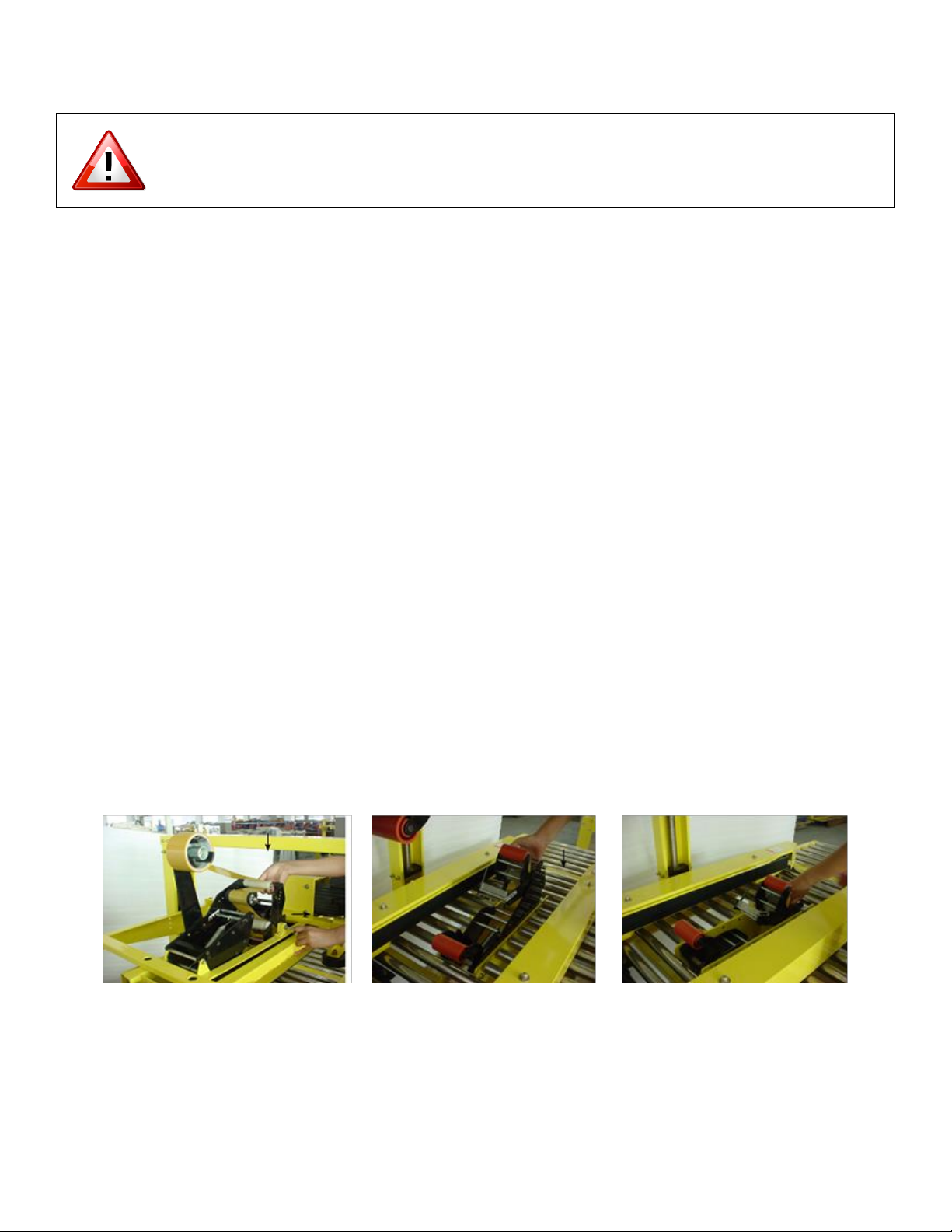
3. Verify that tape is being dispensed in a consistent manner that ensures a smooth application
onto the carton being fed through the machine.
TURN OFF MACHINE AND DISCONNECT IT FROM THE POWER
SOURCE PRIOR TO PERFORMING ANY MAINTENANCE OR SERVICE
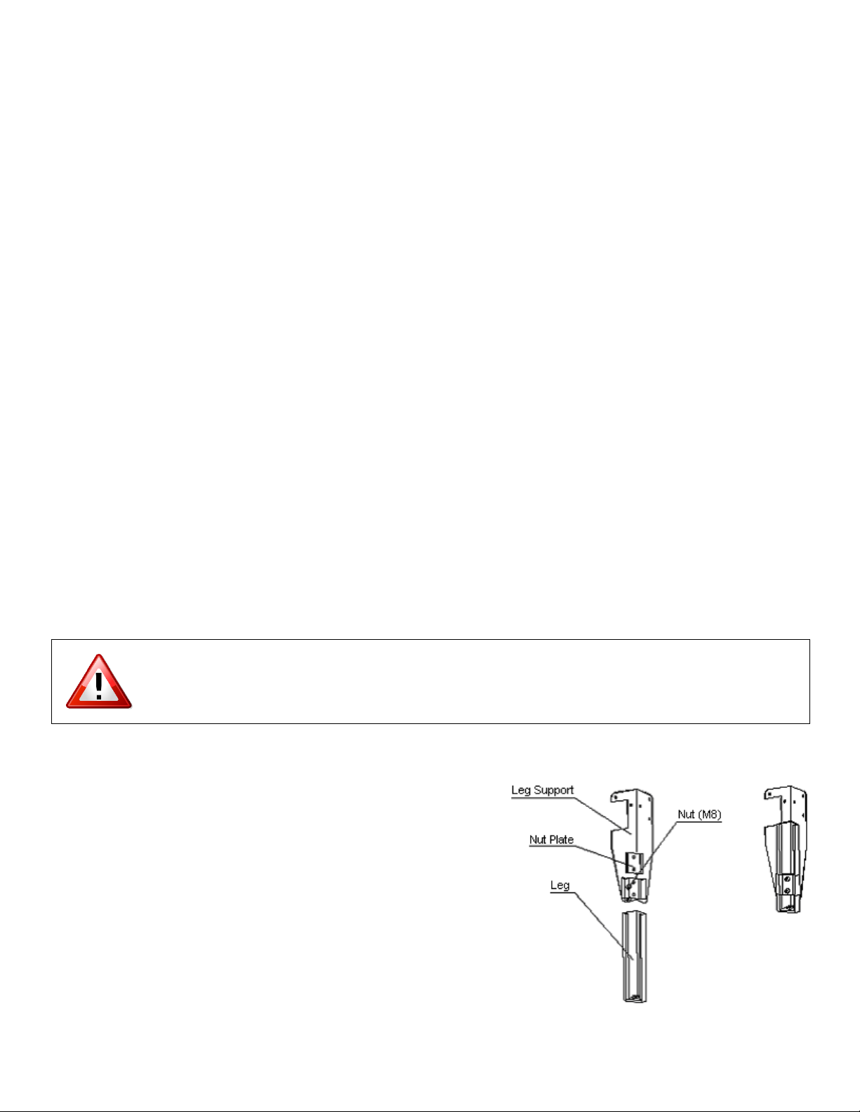
4.2 Adjustable Work Height
Put the nut plate into the leg support according to the
figure.
Then loosely connect the fastening piece and the nut plate
with the socket head cap screws. Insert the leg between the
leg support and nut plate. The leg can now be adjusted up
and down as desired. Tighten the screws.
The working height should be set such that the operator is
able to comfortably reach the roller table while maintaining
approximately 4in (100mm) of distance from the machine.

-8 -
4. Operation
4.3 Feeding the Adhesive Tape
4.4 Adjusting Tape Length
Move the guiding tape wheel from hole #1 to hole #6 to shorten the tape length.
4.5 Top Box Squeezer Adjustment
Adjustment Knob
• Loosen the knobs and move each top
box squeezer in the direction of the
arrows 1 and 2.
• Rollers should touch (aka kiss) the
edge of the carton with a little bit of
pressure.
• This will help squeeze the gap in
between the flaps.
• Top squeezers are mainly used for the
over filled cartons.
• Remember to adjust top squeezers
when changing carton sizes.

-9 -
5. Maintenance and Troubleshooting
TURN OFF MACHINE AND DISCONNECT IT FROM THE POWER
SOURCE PRIOR TO PERFORMING ANY MAINTENANCE OR SERVICE
5.1 Regular Maintenance & Cleaning
1. Check all bolts and screws regularly to ensure smooth, malfunction-free operation of the
machine.
2. Lubricate moving parts of the machine on a regular basis.
3. Clean the machine surfaces.
4. Clean off any tape residue from the cutting blade daily.
5. If the machine is to be stored for an extended period of time, the cutting blade should be oiled
prior to being placed in storage.
5.2 Lubrication
1. The driving chain should be lubricated once a month.
2. The bearings should be lubricated once a month.
3. The transmission axle, driving chain and bearing should be lubricated once a week.
4. All other moving parts should be lubricated on a regular basis.
5.3 Conveyor Belt Adjustment
Adjustments are made using the adjustable bolt located at the
end of the side conveyer system.

-10 -
5. Maintenance & Troubleshooting
5.4 Carriage Height Adjustment
Rotate the height adjustment handle by hand to adjust the carriage height.
Rotate the handle clockwise to move the carriage up and counter clockwise to move the carriage
down.
5.5 Conveyor Width Adjustment
Rotate the width adjustment handle by hand to adjust the conveyor width. Rotate the handle
clockwise to decrease the distance between the conveyors. Rotate the handle counter clockwise to
increase the distance between the handles.

-11 -
5. Maintenance & Installation
5.6 Typical Faults & Solutions
Fault
Solution
Tape is not centered on the carton.
Adjust the tape positioning knob on the tape
head dispenser.
Scratched carton caused by tape cutting blade.
Adjust tape cutting blade position.
Tape is not properly adhering to the carton.
(Caused by forward tape transfer wheel not
applying sufficient force)
Adjust front wheel spring to increase force.
Check for proper tape threading.

-12 -
6. Illustrations & Parts List
6.1Main Frame Components
Description Part Number Qty
1 Machine Frame*1
2 Front Leg Support - Must specify Left or Right FJG-1A-110L or FJG-1A-110R
3 Nut Plate FJG-1A-112 4
4 Leg Extension FJG-1A-113 4
5 Rear Leg Support - Must specify Left or Right FJG-1A-111L or FJG-1A-111R 1/ea
FJG-1A-100
6Support Shaft FJ-1A-68 1
1/ea
If you have a T100L, please be sure to add a -L to the end of the part number for
any part marked with an *
If you have a stainless steel model, please add -SS to any metal part when
ordering.

-13 -
6. Illustrations & Parts List
6.2Upright Post Assembly
Description Part Number Qty
1 Handle FJG-1A-193 1
2 Hub FJG-1A-944 1
3 Handle Mount FJG-1A-917 1
4 Beam*FJG-1A-176 1
5 Chain*06B2 1
6 Height Adjustment Gear FJG-1A-179 2
7 Lift Screw Bearing 6905-ZZ 2
8 Upper Supporting Board FJ-3AS-21 2
9 Lift Screw (Left) FJ-3AS-26 1
10 Upright Post Body*FJ-3AS-24 2
11 Lift Screw (Right)*FJ-3AS-25 1
12 Lift Body*FJ-3AS-19 2
13 Idler Wheel FJ-1B-11 8
14 Nut FJ-3AS-20 2
If you have a T100L, please be sure to add a -L to the end of the part number for
any part marked with an *
If you have a stainless steel model, please add -SS to any metal part when
ordering.

-14 -
6. Illustrations & Parts List
6.3Tape Head Carriage
Description Part Number Qty
1 Bracket - Must specify Left or Right FJG-1A-130L or FJG-1A-130R 2
2 Motor Support FJ-1A-120 1
3 Retaining Plate FJ-1A-703 1
4 Brush Support FJ-1A-701 1
5 Support Bars*2
6 Supporting Shaft FJ-1-440 1
7 Shaft FJ-3A-807 1
8 Spring Holder FJ-3A-808 1
9 Fixed Block FJG-1A-127 1
10 Compression Spring FJ-1A-930 1
11 Sliding Block FJ-3A-806 1
12 Switch Stop/Pointer FJ-3A-450 1
FJ-1AW-131
If you have a T100L, please be sure to add a -L to the end of the part number
for any part marked with an *
If you have a stainless steel model, please add -SS to any metal part when
ordering.

-15 -
6. Illustrations & Parts List
6.4Top Box Squeezer
Description Part Number Qty
1 Knob FJG-1A-197T1
2 Locking Frame FJG-1A-194 1
3 Backing Guard FJG-1A-943 1
4 Frame - Must specify Left or Right FJG-1A-116L or FJG-1A-116R 1
5 Bolt 2
6 Spacer/Washer 2
7 Squeezer Bearing 6203Z 2
8 Contact Roller FJG-1A-142 2
9 Spindle FJG-3A-143 2
FJG-3A-143B
FJG-3A-143W
10 Round Nut FJG-3A-143RN 2
Description Part Number Qty
Complete Left Top Squeezer Assembly TM-TBSA-LA1
Complete Right Top Squeezer Assembly TM-TBSA-RA1
If you have a stainless steel model, please add -SS to any metal part when
ordering.

-16 -
6. Illustrations & Parts List
6.5 Side Conveyor System

-17 -
6. Illustrations & Parts List
6.5 Side Conveyor System (Continued)
Description Part Number Qty
1 Right Lead Nut FJG-1A-927 2
2 Lead Screw (Left/Right)*FJG-1A-1551
3 Cover Plate - Must specify Left or Right FJG-1A-169L or FJG-1A-169R 1/ea
4 Side Belt Cover - Must specify Left or Right FJG-1A-152L or FJG-1A-152R 1/ea
5 Conveyor Support Base - Must specify Left or Right FJG-1A-151L or FJG-1A-151R 1/ea
6 Belt 1867X50X5mm 2
7 Metal Drive Wheel FJG-1A-148 2
8 Transmission Shaft FJ-1A-200 2
9 Driver Wheel Sleeve FJG-1A-208 2
10 Conveyor Bearing 6005 2
11 Bearing Base FJ-3A-116 2
12 Motor Mount Panel FJ-1A-302 2
13 Sliding Sleeve FJ-1A-920 2
14 Guide Shaft*FJ-1A-2011
15 Lead Screw (Left/Right)*FJG-1A-1541
16 Motor - Standard RPM 1670 CV200-20ZG1/G2 2
17 Locating Pins FJG-1A-160 4
18 Connection Pole FJG-1A-162 4
19 Orientation Plate FJG-1A-158 2
20 Left Lead Nut FJG-1A-156 2
21 Tensioning Shaft FJG-1A-141 2
22 Tension Wheel Sleeve FJG-1A-207 4
23 Wheel FJG-1A-149 2
24 Width Adjustment Gear FJ-1A-129 2
Chain for Lower Width Adjusting 06BL 1
26Long Roller Assembly*FJG-1A-182/183L 10
27Screw Retainer Closed Assembly FJ-SR-C-ASSY 3
28Screw Retainer Open Assembly FJ-SR-O-ASSY 1
29Handle Mount Assembly FJG-1A-196A 1
Handle FJG-1A-193 3
Hub FJG-1A-944 1
Handle Mount FJG-1A-917 1
Parts
in 29
If you have a T100L, please be sure to add a -L to the end of the part number
for any part marked with an *
If you have a stainless steel model, please add -SS to any metal part when
ordering.
25 Short Roller Assembly*FJG-1A-182/183S 12

-18 -
6.6Tape Head
Description Part Number Qty
Complete Top Tape Head TAPE HEAD-T 1
Complete Bottom Tape Head TAPE HEAD-B 1
6. Illustrations & Parts List
If you have a stainless steel model, please add -SS to any metal part when
ordering.

-19 -
6. Illustrations & Parts List
6.6Tape Head (Continued)
Description Part Number Qty
1 Side Plate FJ-01-17 1
2 Guide Pulley Assembly - see pg 22 for breakdown FG-GUIDEPA 1
3 One-Way Knurled Roller Assembly - see pg 22 for breakdown FJ-E-34 1
4 Blade Carrier FJ-01-04 1
5 Front Roller Assembly - see pg 20 for breakdown FG-FRROLLERA 1
6 Block FJ-01-00 1
7
8 Stop FJ-40-00 2
9 Side Plate (x3) FJ-01-02 1
10 Shaft FJ-00-02 1
11 Shaft FJ-00-07 1
12 Shaft FJ-00-06 4
13 Side Plate (x2) FJ-01-16 1
14 Shaft Cover FJ-02-09 1
15 Back Roller Side Plate Assembly - see pg 21 for breakdown FG-BKROLLERA 1
16 Brass Washer FJ-02-04 1
17 Connecting Lever FJ-01-14 1
18 Knife Blade Assembly - see pg 23 for breakdown KNIFE BLADE ASSY 1
19 Knife Leveling Piece FJ-01-01 1
20 Tape Hub Assembly - see pg 24 for breakdown FG-TAPEHUBASSY 1
21 Tension Spring - Must Specify Upper or Lower FJ-H-07-U or FJ-H-07-L 1
22 Extension Spring Axis FJ-00-01 1
23 Extension Spring FJ-H-04 1
If you have a stainless steel model, please add -SS to any metal part when
ordering.
Shaft Included in FJ-40-00

-20 -
6. Illustrations & Parts List
6.7 Front Tape Roller Assembly - FG-FRROLLERA (can be order as set)
Description Part Number Qty
1 Front Plate - Must specify Left or Right FJ-01-09L or FJ-01-09R 1
2 Shaft FJ-00-08 1
3 Roller Shaft FJ-E-38-01 1
4 Front Rubber Roller FJ-E-41-01 1
5 Press Spring FJ-11-00 1
6 Gasket FJ-50-100 1
7 Button Head Screw Cap M4x12 1
8 Phillips Flat Head Screw M5x15FHSC 1
9 Press Tape Board FJ-01-05 1
10 Press Board FJ-01-08 1
11 Shaft FJ-00-10 1
12 Axle Sleeve FJ-02-02 2
13 Bearing 6900Z 1
14 Front Claw FJ-50-00 1
15 Guide Tape Wheel Assembly FJ-02-13A 1
16 Axle Sleeve FJ-02-14 1
17 Bearing 688Z 1
18 Bearing HK2020 1
19 Axle Sleeve FJ-02-10 1
20 Shaft FJ-00-11 1
21 Shaft FJ-00-09 1
22 Pulling Spring FJ-H-00 1
If you have a stainless steel model, please add -SS to any metal part when ordering.
This manual suits for next models
2
Table of contents
Other Eagle Food Saver manuals
Popular Food Saver manuals by other brands

Craftworx
Craftworx 1A-DS217 instruction manual

SEVERIN
SEVERIN FS 3602 Dimensions

M. J. MAILLIS GROUP
M. J. MAILLIS GROUP SIAT SK20 Operation and maintenance manual

FoodSaver
FoodSaver V3020 User manual & recipe book

Electrolux
Electrolux Dito 600010 Brochure & specs

Clever Creations
Clever Creations ECO SEALER manual