Eagle 100 Series User manual

- 1 -
Operations Manual
Eagle 100 Strapping Machine
READ ALL INSTRUCTIONS CONTAINED IN THIS
MANUAL PRIOR TO MACHINE INSTALLATION!

- 2 -
Contents
page
1. Machine Specifications 3
2. Machine Safety Information 4
2.1 Operational Safety 4
2.2 Environmental Considerations 4
2.3 Machine Transportation 4
2.4 Operator Position 4
3. Machine Operation 5
3.1 Control Panel Functions 5
3.2 Feeding Strap 6
3.3 Machine Operation 7
4. Maintenance & Troubleshooting 8
4.1 Routine Maintenance 8
4.2 Lubrication 8
4.3 Decelerator 8
4.4 Proximity Switch 8
4.5 Strap Feed 9
4.6 Position Adjustments 9
4.7 Troubleshooting 10
5. Main Parts, Illustrations & Parts List 12
5.1 Commonly Replaced Parts 12
6. Main Parts, Parts Illustrations & Parts List 13
6.1 Carriage Drive Assembly 13
6.2 Slide Assembly 16
6.3 Top Body Assembly 17
6.4 Left Top Knife Assembly 18
6.5 Middle Top Knife Assembly 19
6.6 Right Top Knife Assembly 20
6.7 Spindle Assembly 21
6.8 Heating Body Assembly 22
6.9 Heating Section & Slide Plate 23
6.10 Heating Section Assembly 24
6.11 Strapping Force Assembly 25
6.12 Strapping Pendulum Bar 26
6.13 Pre-Strap Feeding Mechanism 27
6.14 Pendulum Mechanism 28

- 3 -
1. Introduction & Specifications
Introduction
This manual contains safety, operating, and maintenance instructions for the Eagle 100 semi-
automatic power strapping machine. This model is designed to strap packages with plastic strap 1/4-
5/8in (6-15mm) wide. The strap ends are joined by means of a hot knife welding process.
Specifications
Power Supply
110VAC/60Hz (Single Phase)
Strapping Speed
1.5 sec per strap
Strapping Force
Strap Size (Width)
5mm to 5/8in
Core Size
8in x 8in
Machine Dimensions
23in x 35.5in x 30in
Machine Weight
264lbs ()
Tabletop Height
Minimum Carton Size (Side being strapped)
3in
Noise Level
≤ 75db
Operating Environment (Temperature)
32-104ºF (0-40ºC)
Operating Environment (Humidity)
0-98%

- 4 -
2. Components
Strap Dispenser
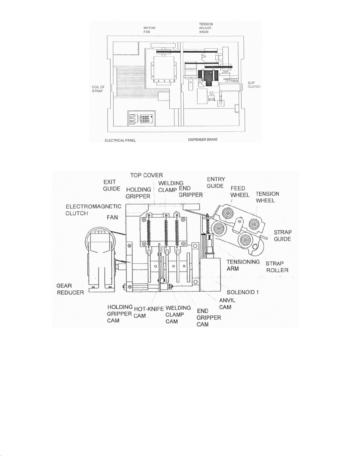
The strap dispenser supplies strapping material to the strapping head. It is located inside the cabinet
on the lower left-hand side. A friction brake is provided to limit over-run of strap.
1. Grip – The grip holds the lead end of the strap beneath the anvil while the remainder of the
strap is being tensioned around the package.
2. Strap Feed & Tension – Both feed and tension are achieved by two sets of gear rollers powered
by an electric motor by means of a drive belt and slip clutch system.
a. An operator controlled adjustable timer controls the duration of strap feed. When the
set time for feeding is up, the timer stops feeding strap. If additional feed is required
beyond that determined by the timer setting, jog feed will be facilitated by pushing the
“Jog” feed button on the operator control panel.
3. Welding & Cut-Off – Welding of the strap ends and cutting of the strap supply are facilitated in
this process.
4. Package Release – After a short weld-cool period (necessary to avoid welded ends from
separating), the package is released.
Functions 1, 3, and 4 are driven by a cam shaft coupled to the drive system by means of an
electromagnetic clutch which turns on full revolution per cycle.
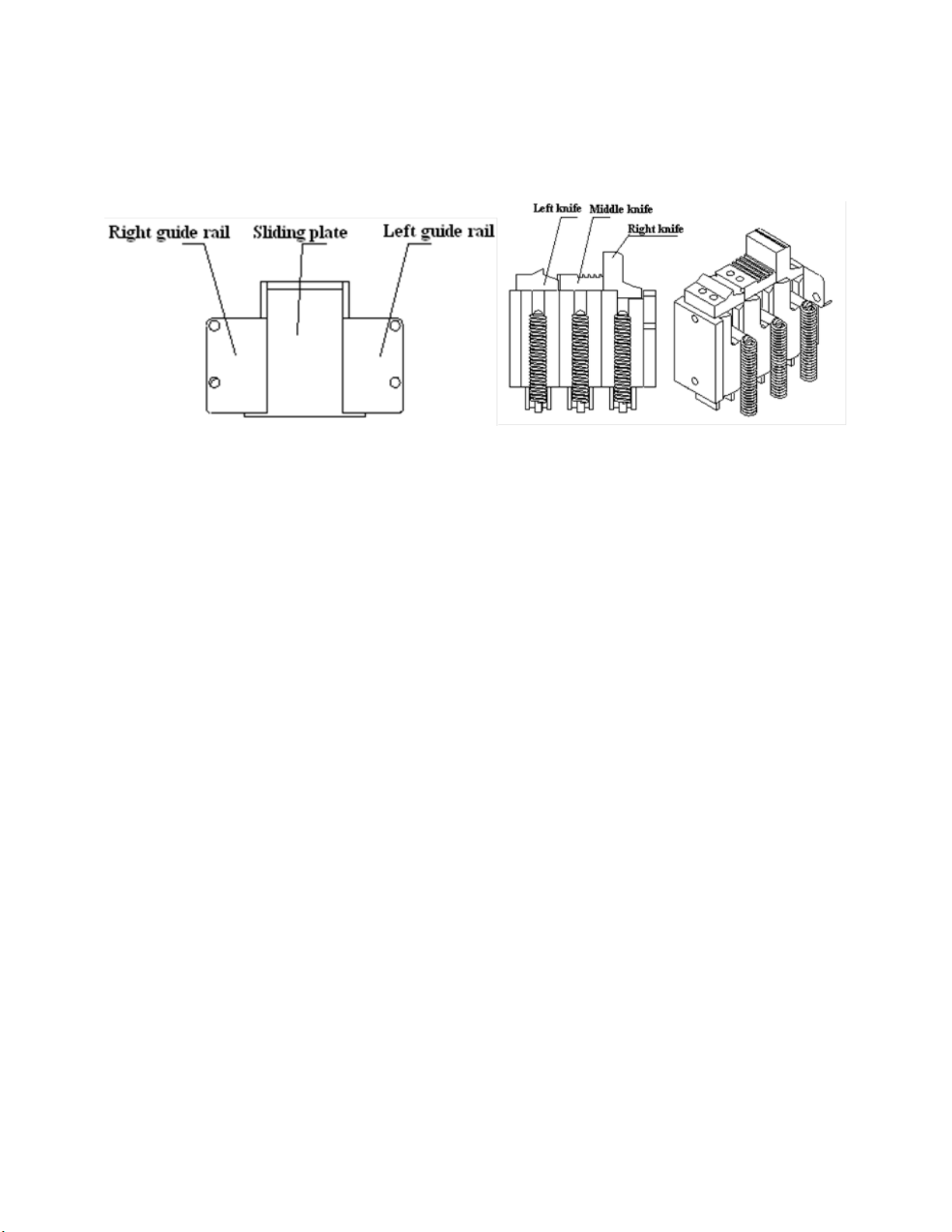
Hot Knife
The “Hot Knife” is centrally located at the front of the strapping head. Movement of the knife is
controlled by a cam.
Electrical System
An all new electrical system using solid state technology supplies continual power to the components
within the machine. Using simple to insert circuit boards, the Eagle 100 provides for safe and relatively
maintenance-free operation.
Operator Controls
The electrical control panel consists of the following control switches/buttons; Main Power, Feed
Length Timer, Reset Switch, Feed Length Switch

- 5 -
2. Components

- 6 -
2. Components

- 7 -
3. Installation
Tools Required
1. Phillips screwdriver (4in)
2. 8mm open-end wrench
3. 10mm open-end wrench
4. 5mm allen wrench
5. 4mm allen wrench
6. 3mm allen wrench
7. 2.5mm allen wrench
Installation
Installation of the Eagle 100 requires placing the tension spring (part number 2201210020) into the
machine and securing it in place using the included caster, spring retainer, and top cover locks.
The screw on the top cap of the speed reducer can be removed for ventilation.
Once strap of the proper size is loaded and the power is connected, operation may begin.
A
895mm
G
400mm
B
740mm
H
230mm
F
565mm
I
110mm

- 8 -
4. Operation
4.1 Operator Controls
The control panel is located on the left-hand side of the front panel of the machine.
1. Power Switch
a. Press the power switch to turn on power to the electrical circuits and the electric motor.
The button will illuminate to show that power has been turned on.
2. Manual Feedback / Reset Switch
a. When lit green, strap can be fed back into the machine. When lit yellow, the button can
be pressed to reset the machine.
3. Manual Feed
a. When in “Reset” mode (green light is illuminated), the Manual Feed button, pressing the
button will cause strap to be manually fed.
4. Length Adjustment Knob
4.2 Cooling Time Adjustment
The cooling time adjustment on your machine allows the user to adjust the cooling time to meet their
strapping requirement. By turning the knob clockwise, the cooling time can be increased.
4.3 Motor Stop Time Dip-Switch Adjustment
The motor stop time adjustment on the machine allows the
user to adjust the motor stop time.
Note: Always power down the machine before adjusting
any dip-switches!

- 9 -
4. Operation
4.4 Loading Strap
1. Pull strap out from the strap reel and check whether the strap head is down. If not, then the
strap reel needs to be turned such that the strap feeds out from the bottom of pulley “A” and
from the top of pulley “B”.
2. Thread the strap through wheel “C” and thread it up to strap slot “D”.
3. Thread the strap along the guide rail to the opening between the rollers.
4. Press the “Feed” button on the control panel for mechanical output of the strapping material.

- 10 -
4. Operation
4.5 Lubrication
1. Lubricate the left knife, middle knife, and right knife of the slide plate once per month
2. The area where the shaft, core, and bearing should be lubricated once every three months.
3. Engine oil should be applied to the gearbox of the decelerator once every two years.
4. While lubricating, don’t use excessive amounts of oil as this may cause micro switch failure.
Avoid soaking micro switches with oil.
5. The following parts/components should not be oiled;
a. Strap feed and return roller
b. Electromagnet
c. Electromagnetic brake
4.6 Temperature Adjustment
In the control cabinet, above the circuit board, open the cover plate of the control panel to access the
temperature controls. The temperature is controlled via a potentiometer. When turned clockwise, the
temperature will be increased. By keeping the adjustment between the values of 4 and 5, the strap
adhesion should remain sufficient.

- 11 -
4. Operation
4.7 Tension Amount
In the control cabinet, above the circuit board, open the cover plate of the control panel to access the
strap tension controls. By turning the potentiometer clockwise, strap tension can be increased. If this
does not increase strap tension, check the pendulum block.
4.8 Strap Width Adjustment
The Eagle 100 accepts strapping material with a width between 6mm and 15mm. To adjust for a given
strap width, adjust the strap insertion hole, the spacing block of the strap output, and the spacing
block width.

- 12 -

- 13 -
4. Operation
4.9 Strap Output Adjustment
In the control cabinet, above the circuit board, open the cover plate of the control panel to access the
strap output control. By turning the potentiometer in a clockwise direction, strap output can be
increased.
4.10 Electromagnetic Brake Adjustment
In the control cabinet, above the circuit board, open the cover plate of the control panel to access the
electromagnetic brake control. By turning the potentiometer in a clockwise direction, the brake can be
adjusted between 0.3mm and 0.5mm. If the setting is too high or low, the electronic brake will not
function properly.

- 14 -
5. Maintenance & Troubleshooting
5.1 Regular Maintenance
1. The sliding plate, left guide rail and right guide rail, should all fit exactly and the forward
movement of the sliding plate must be smooth.
a. Remove the tension spring below the sliding plate.
b. Move the sliding plate backward and remove.
c. Clean the grooves of the sliding plate, left and right guide rail, and retract the spring.
d. Install the sliding plate between the left and right guide rail while retracting the spring.
e. Move the sliding plate forward and backward. Check for smooth movement. If
necessary, adjust the left guide rail. The right guide rail cannot be adjusted.
f. Place a few drops of cart oil or light lubricant in the gap between the sliding plate and
the left/right guide rails.
g. If the sliding plate moves freely, but does not return to the home position, check
whether the tension spring has worn out.
2. The left knife, middle knife and right knife must move up and down smoothly in the chamber
base or the machine will not strap correctly.
a. Take off the tension spring on the middle knife and right knife.
b. Clean middle knife, right knife and the machine chamber base.
c. Reinstall right knife, then the middle knife and finally the tension spring.
If the machine will not be in used for an extended period of time, be sure to apply oil or a light
lubricant to the middle knife and right knife to ensure proper cutting next time the machine is used.
5.2 Typical Faults & Solutions
Strap does not output
Check that the strap has been properly loaded
into the machine.
Strap does not adhere properly
1. Temperature set too high
2. Improper Voltage – Check power source
3. 635 bearing below middle knife damaged –
Replace if necessary
4. Pendulum bar spring fatigued – Replace if
necessary
5. Hot knife is too high/low – Adjust as needed
Nothing happens when strap is fed
1. LS1 (limit switch 1) malfunction – Check,
clean, repair or replace as needed
2. Machine is not at the home position – Reset
machine
Strap tension too low
1. Tension setting too low – Adjust
2. Proximity switch malfunction – Check,
clean, repair or replace as needed
3. Electromagnet malfunction – Check,
clean, repair or replace as needed

- 15 -
6. Illustrations & Parts List
6.1 Main Parts & Components

- 16 -
6. Illustrations & Parts List
Main Parts & Components (Continued)
Description
Part Number
Qty
1
Gear Shaft
1
2
Main Motor Combination
1
3
Left Guide Rail
1
4
Sliding Plate
1
5
Extension Spring (x2)
2
6
Left Knife
1
7
Oblique Gear Shaft
1
8
Right Guide Rail
1
9
Middle Knife
1
10
Bearing
16002
1
11
Right Knife
1
12
Spacing Sleeve
1
13
Right Wallboard
1
14
Roller Wallboard
1
15
Roller
1
16
Bearing
608
1
17
Eccentric Shaft
1
18
Bearing
6900
4
19
Sub Post
1
20
Roller Frame
1
21
Sealing Board
1
22
Swing Block
1
23
Extension Spring Hanging Board
1
24
Strap Guide Plate
1
25
Cover Plate
1
26
Strap Guide Plate
1
27
Sleeve
1
28
Staff
1
29
Circular Clip
D=12
1
30
Circular Clip
D=10
1
31
Eccentric Shaft
1
32
Bearing
16001
2

- 17 -
6. Illustrations & Parts List
6.1 Main Parts & Components (Continued)
33 Bullet Head 1
34 Extension spring (x3) 1
35 Driven Roller 1
36 Driving Roller 1
37 Seat Pad 1
38 Cavity Base 1
39 Pendulum Bar Tongue 1
40 Extension spring (x1) 3
41 Bearing 635 3
42 Feeding and Returning Motor Combination 1
43 Cushion Ring 2
44 Induction Disk 1
45 Pendulum Bar of Sliding Plate 1
46 Extension Spring (x3) 1
47 Heating Plate Frame 1
48 Heating Plate 1
49 Pendulum Bar Shaft 1
50 Bearing 635 1
51 Heating Pendulum Bar 1
52 Extension spring (x1) 2
53 Stop Collar 1
54 Bearing 635 1
55 Main Shaft 1
56 Bearing 6004 2
57 Spacing Sleeve 6
58 Cam (5) 1
59 Cam (4) 1
60 Cam (3) 1

- 18 -
6. Illustrations & Parts List
6.1 Main Parts & Components (Continued)
61 Cam (2) 1
62 Cam (1) 1
63 Left Wallboard 1
64 Big Gear Wheel 1
65 Electric Magnet 1
66 Spacing Plate of Strap Inserting Path 1
67 Strap Feeding Bottom Plate 1
68 Spacing Plate 1
69 Strap Feeding Pressure Plate 1
70 Strap Inserting Path Bottom Plate 1
Other manuals for 100 Series
1
Table of contents
Other Eagle Packaging Equipment manuals
Popular Packaging Equipment manuals by other brands

Francotyp-Postalia
Francotyp-Postalia FPi 5020 Operator's manual

Fromm
Fromm FS15 Series Service manual

Barry-Wehmiller
Barry-Wehmiller BW Integrated Systems Streamfeeder V-1400IJ manual

ITATOOLS
ITATOOLS ITA30 Operation manual

3M
3M AccuGlide II STD 3 Inch Instructions and parts list

honor
honor VFJ-520 manual

Sprintis
Sprintis ATG-900 Instruction

Atlanta Attachment Company
Atlanta Attachment Company 1390BX Technical Manual & Parts Lists

Rice Lake
Rice Lake ISHIDA WM-Nano manual

Superabrasive
Superabrasive LAVINA V25E115 user manual

Orgapack
Orgapack OR 4000.13 manual

Signode
Signode AL-12/38 Operation, parts and safety manual