Table of Contents
Safety information, power specications ................................................................. 2
About this guide .................................................................................................... 3
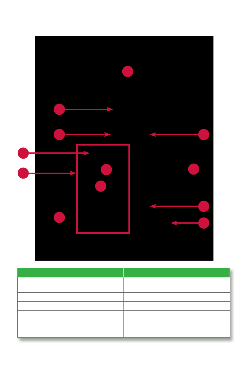
Strapping module diagram ..................................................................................... 4
Corner module diagram ......................................................................................... 6
Maintaining bins.................................................................................................... 7
Maintaining paper rolls .......................................................................................... 8
Maintaining printer ribbon cartridge ...................................................................... 10
Conguring strap length and printing .................................................................... 11
Stopping conditions and recovery steps ................................................................ 15
Daily cleaning procedures .................................................................................... 22
2|JetScan®MPX 8200 strapping and corner module | Safety information, power specications
Safety information, power specifications
High voltage inside. Risk of electric shock.
Do not attempt repairs. Repairs must be made by authorized
Cummins Allison personnel.
Use grounded plug and properly grounded outlet.
Read and understand all instructions before use.
Risk of injury.
Press MPX 8200 master power switch OFF before cleaning any
automatic-strapping module and any corner module.
Do not defeat safety interlock switches.
Improper voltage levels can cause equipment malfunction,
damage electrical components, and void warranty.
Provide separate circuit serving only this device and follow listed
power requirements to ensure proper operation.
Provide power conditioning/stabilizing devices if necessary.
Automatic-strapping module
•Voltageoperatingrange: 105-130 VAC
•Frequency: 50/60 Hz
•Fullloadamps(FLA): 3A
•Electricalsupplycircuit: The customer must provide a single-phase, dedicated power line that meets the
machine’s power requirements. Use a properly grounded circuit breaker in compliance with applicable local
electrical code.
Corner module
The corner module does not have a power cord or a power switch. It obtains power from the adjacent
automatic-strapping module.
Environmentaloperatingconditions
•Temperature: 60°F - 85°F (15°C - 29°C)
•Humidity: 30% to 70% (non-condensing)
Compliance acknowledgments
•Laser: This equipment may contain Class 2 laser products and complies with FDA Radiation Performance
Standards, 21 CFR Subchapter 1 and the international laser safety standard IEC-60825.1-2001-08.
• FCC: This device complies with part 15 of the FCC rules. Operation is subject to the following two conditions:
(1) this device may not cause harmful interference, and (2) this device must accept any interference received,
including interference that may cause undesired operation.