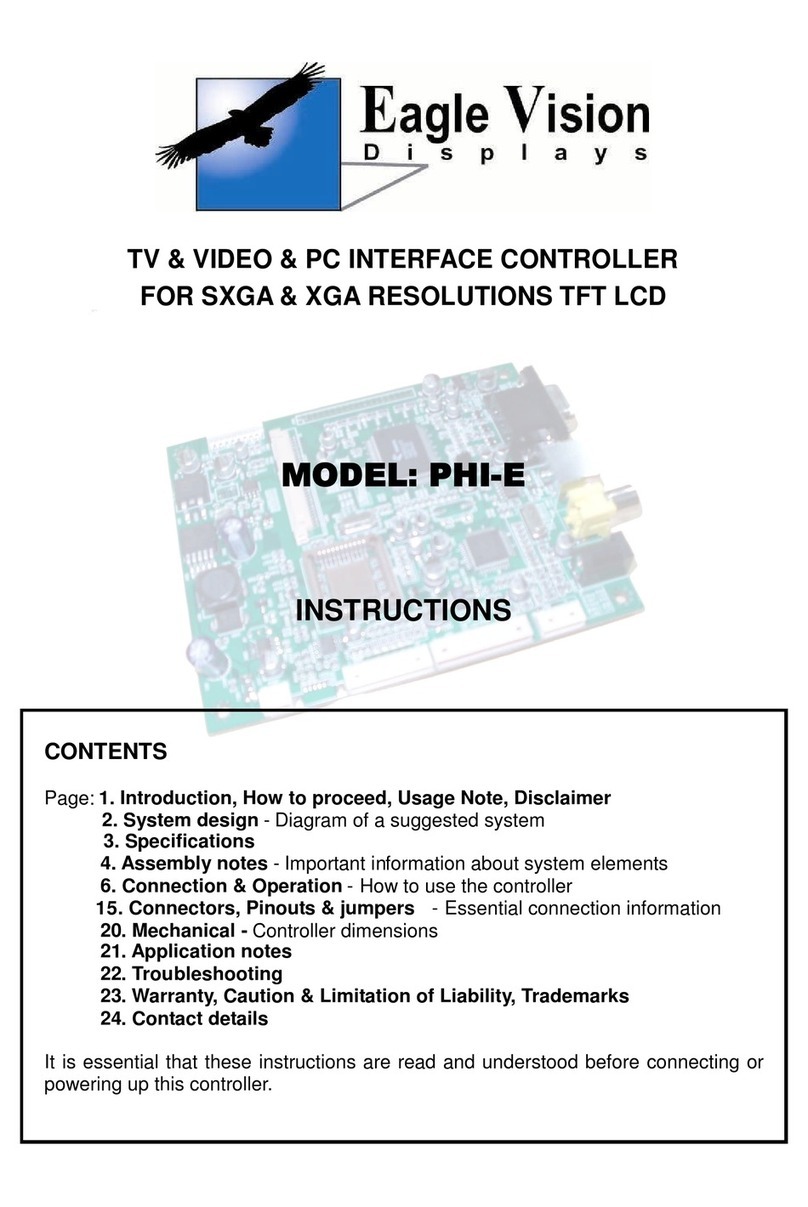
EagleVision EON-ADVS User manual

TV & VIDEO & PC INTERFACE CONTROLLER
FOR UXGA & WSXGA RESOLUTIONS TFT LCD
(INCLUDES AUDIO SOLUTION)
MODEL: EON-ADVS
INSTRUCTIONS
CONTENTS
Page: 1. Introduction, How to proceed, Usage Note, Disclaimer
02. System design - Diagram of a suggested system
03. Specifications
4. Assembly notes - Important information about system elements
6. Connection & Operation - How to use the controller
12. Connectors, pinouts & jumpers - Essential connection information
20. Mechanical - Controller dimensions
21. Troubleshooting
22. Warranty, Caution & Limitation of Liability, Trademarks
23. Contact details
It is essential that these instructions are read and understood before connecting or
powering up this controller.

1
INTRODUCTION
Designed for LCD monitor and other flat panel display applications the EON-ADVS
controller provides easy to use interface controller for:
TFT LCD panels of 1600×1200, 1680×1050, 1280×1024, 1366×768, 1024×768, 800×600
resolutions.
Computer video signals of VGA, SVGA, XGA, WXGA, SXGA, WSXGA and UXGA
standard.
DVI input support up to UXGA input signals
Video signals of NTSC, PAL and SECAM standard.
TV signal input (optional add-on board required).
Volume control of audio.
HOW TO PROCEED
Make sure you have all parts & that they are correct, refer to:
Connection Diagram (separate document for each panel)
Connection reference (in following section)
Assembly notes
Check controller switch & jumper settings (errors may damage the panel)
Prepare the PC
Connect the parts
Understand the operation & functions
IMPORTANT USAGE NOTE
This equipment is for use by developers and integrators, the manufacturer accepts no liability for
damage or injury caused by the use of this product. It is the responsibility of the developer,
integrators or other user of this product to:
Ensure that all necessary and appropriate safety measures are taken.
Obtain suitable regulatory approvals as may be required.
Check power settings to all component parts before connection.
DISCLAIMER
There is no implied or expressed warranty regarding this material.

2
SYSTEM DESIGN
A typical LCD based display system utilizing this controller is likely to comprise the following:
Max. 15 mm
100mm
80mm
J100/J100A J200 J300 J700 J706 J500 J501 J707 J708
J704
J705
EON
-
ADVS
12V
5V
3.3V
JP120
CN500
J703 CN400
CN100
CN101
CN701
CN700

3
SPECIFICATIONS
Panel compatibility Compatible with 1600×1200, 1680×1050, 1280×1024, 1366×
768, 1024×768 & 800×600 resolutions of TFT LCD panels from
manufacturers such as:
LG, Samsung,AUO, Hydis, etc
Some factory adjustment may be required for individual panel
timings.
NO, of colors Up to 3×8 bit providing 16.7million
Panel power +3.3V DC, +5V DC, +12V DC
Panel signal LVDS
Graphics modes Standard VGA, SVGA, XGA, WXGA, SXGA, WSXGA, UXGA
Graphics mode auto detect VGA, SVGA, XGA, WXGA, SXGA, WSXGA, UXGA
Standard input at source Analog VGA (15 pin)
DVI
S-Video
Composite video
TV
Controls available Power On/Off
OSD Menu
Channel Up/Down
Volume Up/down
Select Source (PC / Composite Video / S-Video / TV)
Settings memory Settings are stored in non volatile memory (flash memory)
OSD Menu functions Picture, Geometry, Function (Menu items)
Voltage output for LCD +3.3V DC, +5V DC, +12V DC
Input voltage +12V DC
Power load maximum The controller has an overall 3Amp current limit
Storage temperature limits -55 ~ +125 ㎜
Operating temperature limits 0 ~ + 70 ㎜
Controller dimensions 190㎜× 130㎜× 15㎜
NOTES
Please note the following:
In a special case that there are a large order re-layout and custom development services
are available. (After discussion, it’ll be decided)
For specific panel setup, it’s also same case.
For the detail, contact us please. (Please note the Contact Details section)

4
ASSEMBLY NOTES
This controller is designed for monitor and other flat panel display applications using 1600×1200,
1680×1050, 1280x1024, 1366×768, 1024×768, and 800×600 resolution TFT panels with a VGA,
SVGA, XGA, WXGA, SXGA,WSXGA or UXGA signal input. The following provides some
guidelines for installation and preparation of a finished display solution.
Preparation: Before proceeding it is important to familiarize yourself with the parts making up the
system and the various connectors, mounting holes and general layout of the controller. Guides to
connectors and mounting holes are shown in the following relevant sections.
1. LCD Panel: This controller is for TFT panels with 3.3V, 5V, and 12V LVDS interface. Due to the
variation between manufacturers panels signal timing and other panel characteristics, factory setup
and confirmation should be obtained before connecting to a panel. (NOTE: Check panel power
jumper settings before connection)
2. Controller: Handle the controller with care as static charge may damage electronic components.
Make sure the relevant connection and operation to match the target LCD panel.
3. LCD connector Board: Different makes and models of LCD panel require different panel signal
connectors and different pin assignments.
4. LCD signal Cables: In order to provide a clean signal it is recommended that LCD signal cables
should be not longer than about 30㎜. Care should be taken when placing the cables to avoid
signal interference.
5. Inverter: This will be required for the backlight of an LCD, some LCD panels have an inverter
built in. As LCD panels may have one or more backlight tubes and the power requirements for
different panel backlights may vary it is important to match the inverter in order to obtain optimum
performance. SeeApplication notes for more information on connection.
6. Inverter Cables: Different inverter models require different cables and different pin assignment.
Make sure correct cable pin out to match inverter. Using wrong cable pin out may damage to
inverter.
7. Function Controls: The following section discusses the controls required and the section on
connectors provides the detail. The controls are minimal: OSD (7 momentary buttons) digital type.
8. Function Controls Cable: The cables to the function switches should be of suitable quality and
length so that impedance does not affect performance. Generally lengths up to 1 meter should be
acceptable.
9. VGA Input Cable: As this may affect the quality of the signal to the controller a suitably shielded
jack should be utilized.
10. DVI Input Cable: Plug the DVI cable to the connector J200 on the controller board.
11. Composite Video Cable: It’s Composite video jack. Reasonable quality cable should be used
to avoid image quality degradation.
S-Video Cable: It’s for S-Video signal.

5
12. TV tuner & cable: It’s for TV. TV tuner add-on board is required. There are three types of video
format: PAL, NTSC & SECAM.
13. Audio: It is possible to control volume through the OSD menu.
14. Status LED: The pin direction of the LED should be corrected for right color indication. Red
color stands for standby. Green colors stands for signal on.
15. Power Input: 12V DC is required, this should be a regulated supply. The power rating is
depending on the panel and inverter used. Normally, power supply with 3.0∼3.5Amp current output
should enough for most of TFT LCD panels. Although the controller provides power regulation for
the LCD power this does not relate to the power supplied to the backlight inverter.
If an unregulated power supply is provided to an inverter any fluctuations in power may affect
operation, performance and lifetime of the inverter and or backlight tubes.
16. Power Output: Note the controller has an overall 3Amp current limit .
17. Ground: The various PCB mounting holes are connected to the ground plane.
18. Controller Mounting: It is recommended that a clearance of at least 10㎜is provided above
and 5㎜below the controller when mounted. Additionally consideration should be given to:
Electrical insulation.
Grounding.
Cable management. (Note: It is important to keep panel signal cables apart from the
inverter & backlight cables to prevent signal interference.)
Heat & Ventilation: Heat generated from other sources, for example the backlight of a
very
high brightness panel may generate significant heat, which could adversely
affect the controller.
Other issues that may affect safety or performance.
19. PC Graphics Output: A few guidelines:
Signal quality is very important, if there is noise or instability in the PC graphic output this
may result in visible noise on the display.
Refer to graphics modes table in specifications section for supported modes.
Non-interlaced & interlaced video input is acceptable.
NOTE: Please read the Application Notes section for more information.

6
CONNECTION & OPERATION
CAUTION: Never connect or disconnect parts of display system when the system is powered up
as this may cause serious damage.
CONNECTION
It is useful to have the relevant connection diagram available at this time:
1. LCD panel & Inverter: Connect the inverter (if it is not built-in the panel) to the CCFT lead
connector of the LCD panel.
2. LVDS type panels: Plug the signal cable direct to CN100 or CN101. Then insert another end of
cable to the LCD panel connector.
3. Inverter & Controller: Plug the inverter cable to J705 on the controller board (if necessary).
Plug another end to the connector on the inverter.
4. Function switch & Controller: Plug the OSD switch mount cable to CN400 on the controller
board and another to the OSD switch mount. (Please read the following section for more
information.)
5. PC VGA Cable & Controller: Plug the VGACable to J300 on the board.
6. DVI Cable: Plug the DVI Cable to the connector J200 on the controller board.
7. Composite Video Cable & Controller: Plug the RCAcable to J500 on the board.
S-Video Cable: Plug the S-Video Cable to J501 on the board.
8. TV tuner add-on board cable & Controller:
Plug the TV tuner cable to J704 on the controller board.
9. Audio Input cable (from PC) & Controller: Plug this cable to CN601 on the controller board.
Audio Input cable (from Video) & Controller: Plug this cable to J707(Right) and J708(Left) on
the controller board.
Audio Output cables (for PC speakers): Plug the cable to J706 on the controller board.
Audio Output cables (for speakers): Plug the cable to CN700 and CN701 on the controller
board.
10. Jumpers & Panel voltage: JP120 is used for panel voltage input (read panel specification and
information on the jumper table to define the correct settings).
11. Power supply & Controller: Plug the DC 12V power in to the connector J100on the controller
board.
12. Power on: Switch on the controller board and panel by using OSD switch mount.

7
General:
If you are using supplied cables & accessories, ensure they are correct for the model of
panel and controller.
If you are making your own cables & connectors refer carefully to both the panel & inverter
specifications and the section in this manual, "Connectors, Pinouts & Jumpers" to ensure the
correct pin-to-pin wiring.
PC SETTINGS
The control has been designed to take a very wide range of input signals however to optimize the
PC’s graphics performance we recommend choosing 60Hz vertical refresh – this will not cause
screen flicker.
OPERATION
Once the system has been connected and switched on there are a number of functions available to
adjust the display image as summarized in the following sections. The settings chosen will be
saved for each mode independently.

8
LCD DISPLAY SYSTEM SETTINGS
NOTE: By way of explanation the following refers to a set of sample buttons that may be obtained
as an option. In addition to power On/Off and connection for backlight brightness the controller
provides an On Screen Display of certain functions, which are controlled by 7 momentary type
buttons(digital type).
Controls Digital type
MENU / EXIT
turns OSD menu On (it will auto time off) / turns OSD
menu Off MENU button
DOWN / CH-
moves the selector to the previous function / decrease the
setting (after confirming)
moves the previous channel
DOWN button
UP / CH+
moves the selector to the next function / increase the
setting (after confirming)
moves the next channel
UP button
LEFT / VOL-
decrease the volume LEFT button
RIGHT / VOL+
increase the volume RIGHT button
SOURCE
Select a main Input signal SOURCE button
POWER
Power On / Off POWER button
Status LED
shows the controller mode
Green : Normal, Orange : Power saving, Off : Power off Header pin 3×1
NOTE: The PC needs to be set to the appropriate graphics mode for the resolution of the panel (if
the panel has flickering or flashing display, the vertical refresh rate should be set to 60㎜or less.)
Function Controls
(Di
g
ital type)
UP
SOURCE
POWER
MENU
DOWN
LED
RIGHT
LEFT

9
OSD Functions
OSD Structure
Main Menu – Image Adjustment
Sub Menu Explanation
Brightness Adjust the Brightness of the screen.
Contrast Adjust the Contrast of the image.
Clock Adjust the clock pulse of the image.
Phase Adjust the focus of the image.
H. Position Move the image left and right on the screen.
V. Position Move the image up and down on the screen.
Sharpness Adjust the picture sharpness of lower resolutions.

10
OSD Structure
Main Menu – Color Temp. Selection
Sub Menu Explanation
9300K Set up the color temp. to be 9300K white color.
7500K Set up the color temp. to be 7500K white color.
6500K Set up the color temp. to be 6500K white color.
User RED
User GREEN
User Blue
Adjust red / green / blue gain.
Main Menu – Language Selection
Sub Menu Explanation
English / Français /
Deutsch / Español /
Italiano / 本本本 /
Русский/本本本本 /
㎜㎜㎜㎜
Select the language you want

11
OSD Structure
Main Menu – Settings
Sub Menu Explanation
OSD Time Out Adjust OSD display time setting.
OSD Position Move OSD display position to any one of the following 5 positions within the
overall screen.
OSD Transparent Increase / decrease transparency.
Auto Setting Set up to adjust clock, phase and positions automatically.
Recall Restore to factory settings.
Aspect Ratio Adjust the screen size.

12
Connectors, Pinouts & Jumpers
The various connectors are:
Max. 15 mm
100mm
80mm
J100/J100A J200 J300 J700 J706 J500 J501 J707 J708
J704
J705
EON
12V
5V
3.3V
JP120
CN500
J703 CN400
CN100
CN101
CN701
CN700

13
Summary:
Ref. Purpose Description
CN400 OSD controls YeonHo connector 10-pin (20017WS-10)
J703 IR controls YeonHo connector 8-pin (SMW200-08P)
CN100 /
CN101 LCD signal (LVDS) Header Hirose 30-pin (12507WR-30)
J705 Backlight inverter YeonHo connector 7-pin (SMW200-07P)
JP120 Panel power control jumper 1-2 H=12V, 3-4 H=5.0V, 5-6 H=3.3V
J200 DVI-I signal Input 24 Pin DVI-I
J300 Analog VGA signal input DB15 high density PCB mount, 3 row, r/angle
J500 S-Video signal Input Mini din 4-way
J501 AV signal Input (Composite) RCA jacks (Yellow).
CN500 AV signal Input YeonHo connector 4-pin (20017WS-04)
J704 TV tuner add-on board YeonHo connector 10-pin (SMW200-10P)
J700 Audio In (from PC) Stereo phone jack (ST037-06)
J704 Audio signal Output
(Speaker or Earphone) Stereo phone jack (ST037-06)
J707 Audio signal Input(Right) RCA jacks (White)
J708 Audio signal Input(Left) RCA jacks (Red)
CN700 Audio signal Output(Speaker) YeonHo connector 2-pin (SMW200-02P)
CN701 Audio signal Output(Speaker) YeonHo connector 2-pin (SMW200-02P)
J100 Main power Input (12V DC) Power Jack, 2.5mm internal pin (DS210)

14
CN400 – To OSD controls : YeonHo connector 10pin
Pin Symbol Description
1 POWER Function control signal(For POWER)
2 LED_GRN Green LED Signal
3 EXIT Function control signal(For ECIT)
4 DOWN Function control signal(For DOWN)
5 AUTO
6 BRIGHT
7 MENU Function control signal(For MENU)
8 GND Ground
9 UP Function control signal(For UP)
10 SELECT Function control signal(For SELECT)
J703 – To IR controls : YeonHo connector 8pin
Pin Symbol Description
1 ADC0
2 ADC1
3 DGND
4 5V+
5 IR_INT
6 DGND
7 ORANGE
8 GREEN
CN100 – To LCD panel (LVDS) : YeonHo connector 30pin
Pin Symbol Description Pin Symbol Description
1T0M LVDS pair 0 negative output 16 T5P LVDS pair 5 positive output
2T0P LVDS pair 0 positive output 17 DGND Ground
3T1M LVDS pair 1 negative output 18 T6M LVDS pair 6 negative output
4T1P LVDS pair 1 positive output 19 T6P LVDS pair 6 positive output
5T2M LVDS pair 2 negative output 20 TCLK2M Clock pair 2 negative output
6T2P LVDS pair 2 positive output 21 TCLK2P Clock pair 2 positive output
7DGND Ground 22 T7M LVDS pair 7 negative output
8TCLK1M Clock pair 1 negative output 23 T7P LVDS pair 7 positive output
9TCLK1P Clock pair 1 positive output 24 DGND Ground
10 T3M LVDS pair 3 negative output 25 N.C Not Connected
11 T3P LVDS pair 3 positive output 26 N.C Not Connected
12 T4M LVDS pair 4 negative output 27 N.C Not Connected
13 T4P LVDS pair 4 positive output 28 LCDVDD Panel VCC
14 DGND Ground 29 LCDVDD Panel VCC
15 T5M LVDS pair 5 negative output 30 LCDVDD Panel VCC

15
CN101 – To LCD panel (LVDS) : YeonHo connector 30pin
Pin Symbol Description Pin Symbol Description
1LCDVDD Panel VCC 16 TCLK1P Clock pair 1 positive output
2LCDVDD Panel VCC 17 T3M LVDS pair 3 negative output
3LCDVDD Panel VCC 18 T3P LVDS pair 3 positive output
4N.C Not Connected 19 DGND Ground
5N.C Not Connected 20 T4M LVDS pair 4 negative output
6DGND Ground 21 T4P LVDS pair 4 positive output
7N.C Not Connected 22 T5M LVDS pair 5 negative output
8DGND Ground 23 T5P LVDS pair 5 positive output
9T0M LVDS pair 0 negative output 24 T6M LVDS pair 6 negative output
10 T0P LVDS pair 0 positive output 25 T6P LVDS pair 6 positive output
11 T1M LVDS pair 1 negative output 26 TCLK2M Clock pair 2 negative output
12 T1P LVDS pair 1 positive output 27 TCLK2P Clock pair 2 positive output
13 T2M LVDS pair 2 negative output 28 T7M LVDS pair 7 negative output
14 T2P LVDS pair 2 positive output 29 T7P LVDS pair 7 positive output
15 TCLK1M Clock pair 1 negative output 30 DGND Ground
J705 – To Backlight Inverter : YeonHo connector 7pin
Pin Symbol Description
1 BL_VCC Power supply pin
2 BL_VCC Power supply pin
3 BL_ON To turn backlight On/Off
4 BL_BRIGHT PWM signal for backlight control.
5 DGND Ground
6 DGND Ground
7 DGND Ground
JP120 – To switch the panel voltage
Pin Symbol Description
112Vcc 12V DC
2DGND Ground
35Vcc 5V DC
4DGND Ground
53.3Vcc 3.3V DC
6DGND Ground

16
J200 – To PC: DVI-I signal input
Pin Symbol Description
1 RX2- DVI input pair 2-
2 RX2+ DVI input pair 2+
3 GND Ground
4 RX4- No Connection
5 RX4+ No Connection
6 DDC_SLK DDC Clock
7 DDC_DAT DDC Data
8 AVS No Connection
9 RX1- DVI input pair 1-
10 RX1+ DVI input pair 1+
11 GND Ground
12 RX3- No Connection
13 RX3+ No Connection
14 5V +5V Power
15 GND Ground
16 HPD Hot Plug Detect
17 RX0- DVI input pair 0-
18 RX0+ DVI input pair 0+
19 GND Ground
20 RX5- No Connection
21 RX5+ No Connection
22 GND Ground
23 RXC+ DVI Clock+ input pair
24 RXC- DVI Clock- input pair
C1 AR No Connection
C2 AG No Connection
C3 AB No Connection
C4 AHS No Connection
C5 NC Ground

17
J300 – To Analog VGA input : DB15 high density PCB mount, 3 row, r/angle
Pin Symbol Description
1 DB_R+ Red analog In
2 DB_G+ Green analog In
3 DB_B+ Blue analog In
4 N.C. Open
5 VGA_DET Reserved for monitor ID bit 0 (DSUB_ID)
6 JDGND Ground
7 JDGND Ground
8 JDGND Ground
9 DDC_VDD DDC VDD
10 JDGND Ground
11 N.C. Open
12 DDC_SDA DDC Data
13 VGA_HS Horizontal Sync
14 VGA_VS Vertical Sync
15 DDC_SCL DDC Clock
NOTE: DDC(direct digital control)
J500 – To S-Video signal Input : Mini din 4-way
Pin Symbol Description
1 NC No Connection
2 NC No Connection
3 DGND Ground
4 NC No Connection
5 DGND Ground
6 SVHS_Y Y Signal (MUX2)
7 NC No Connection
8 SVHS_C C Signal (CIN0)
9 DGND Ground
J500 – To AV signal Input (Composite) : RCA jacks (Yellow)
Pin Symbol Description
1 CVBS1_IN Composite Video Signal (YMUX0)
2 NC No Connection
3 GND Ground
4 NC No Connection

18
CN500 – To AV signal Input : YeonHo connector 4pin
Pin Symbol Description
1 CVBS2_IN Composite Video Signal (YMUX2)
2 YGND Ground
3 CVBS3_IN Composite Video Signal (YMUX3)
4 YGND Ground
J704 – To TV tuner add-on board : YeonHo connector 10pin
Pin Symbol Description
1 TSCL I2C Bus Clock out
2 TSDA I2C Bus Data out
3 5V+ 5V DC
4 5V+ 5V DC
5 DGND Ground
6 NC No Connection
7 TV_AUDIO Audio signal In (SIF)
8 DGND Ground
9 CVBS_2IN Composite video signal In
10 DGND Ground
J700 – To PC Audio input: Stereo phone jack (ST037-06)
Pin Symbol Description
1 AGND Ground
2 PC_AUD_L Audio signal (Left)
3 NC No Connection
4 PC_AUD_R Audio signal (Right)
5 NC No Connection
J704 – To PC Audio output: Stereo phone jack (ST037-06)
Pin Symbol Description
1 AGND Ground
2 EAR_L Audio signal (Left)
3 SP_L Audio signal (Left)
4 SP_R Audio signal (Right)
5 EAR_R Audio signal (Right)

19
J707 – To Audio signal Input (Right) : RCA jacks (White)
Pin Symbol Description
1 AV_AUD_R Composite Audio Signal
2 NC No Connection
3 GND Ground
4 NC No Connection
J708 – To Audio signal Input (Left) : RCA jacks (Red)
Pin Symbol Description
1 AV_AUD_L Composite Audio Signal
2 NC No Connection
3 GND Ground
4 NC No Connection
CN700 – To Audio signal Output(Speaker): YeonHo 2pin
Pin Symbol Description
1 OUT1+ Audio signal (Left)
4 OUT1- Ground
CN701 – To Audio signal Output(Speaker): YeonHo 2pin
Pin Symbol Description
1 OUT2+ Audio signal (Right)
4 OUT2- Ground
J100 – To Main power 12V input : Power jack (2.5㎜internal pin)
Pin Description
1+12V DC in middle pin
2Ground
Other EagleVision Controllers manuals
Popular Controllers manuals by other brands

Honeywell
Honeywell UDC 6300 Replacement Instruction

Siemens
Siemens Sirius 3RA6 System manual

Eurotech
Eurotech Helios Hardware reference manual

Pego
Pego Vision Touch Wellness User and maintenance manual

RKC INSTRUMENT
RKC INSTRUMENT THW-3 Series quick start guide

Unitronics
Unitronics UniStream USC-B3-R20 installation guide