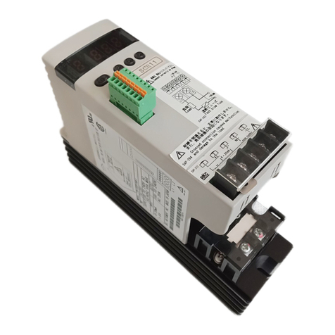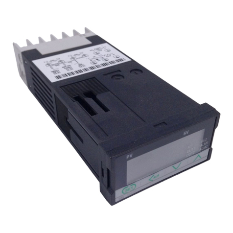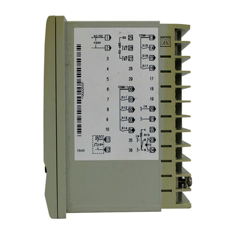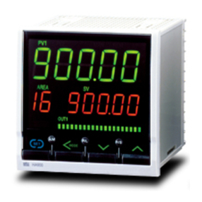
Specifications
: Check item :
Board check, EEPROM check
Adjustment data check, Set value range check
Action at abnormality :
FAIL lamp ON, Thyristor output OFF
(The alarm output can be output from the alarm
terminals.)
Self-diagnostic
function
: 20A, 30A, 45A, 60A, 80A, 100A AC
Max. load current
: 0 to 98% of rated voltage
: 1A
: Less than 17VA (200V type), Less than 21VA (400V type)
Power consumption
Min. load current
: a) 90 to 264V AC (Including power supply voltage variation)
Rating : 200 to 240V AC
b) 360 to 484V (Including power supply voltage variation)
Rating : 400 to 440V AC
* Power supply voltage for control circuit voltage is 180
to 264VAC. A step-down transformer is supplied with
the main unit
(Including power supply voltage variation)
Rating : 200 to 240V AC
Control method
Applicable load
: Group 1 (Field-programmable within Group)
Current input 4 to 20mA DC (Input impedance : 100Ω)
Current input 0 to 20mA DC (Input impedance : 100Ω)
Voltage input 0 to 5V DC (Input impedance : 30kΩ)
Voltage input 1 to 5V DC (Input impedance : 30kΩ)
Voltage pulse input 0/12V DC (Input impedance : 30kΩ)
Non-voltage contact input
Group 2 (Field-programmable within Group)
Voltage input 0 to 10V DC (Input impedance : 68kΩ)
Voltage pulse input 0/12V DC (Input impedance : 68kΩ)
Voltage pulse input 0/24V DC (Input impedance : 68kΩ)
Non-voltage contact input
Input signal
0
20
40
60
80
100
10 20 30 40 50 55
Function
Constant voltage
variation
Constant current
variation
Constant power
variation
Operating condition Stability
Power supply variation
: Within ±10%
Load variation
: 2 times
Power supply variation
: Within ±10%
Load variation
: 2 times
Power supply variation
: Within ±10%
Load variation
: 2 times
Within ±2%
of full scale
Within ±2%
of full scale
Table of Stability
Table of internal calorific value
Max.load
current (A)
Internal calorific
value (W)
20 30 45 60 80 100
82 118 172 226 298 370
: Phase control/ Zero-cross control (Selectable)
: Phase control : Linearity (R:Resistor) load, Control of primary
side of a transformer (magnetic field density
8,000 gauss or less)
Zero-cross control : Linearity (R:Resistor) load
Output voltage range
Power supply voltage
: 50/60Hz (Automatic discriminating)
Power frequency
: 50±1Hz, 60±1Hz (Performance guarantee range)
45 to 54.9Hz (50Hz), 55 to 64.9Hz (60Hz)
(Operating guarantee range)
Allowable power
frequency variation
: Gradient setting : 0.0 to 100%
[Front key or external setting unit]
Output limiter (High) : 0.0 to 100.0% [Front key]
Output limiter (Low) : 0.0 to 100.0% [Front key]
Output limiter at start-up (High)
: 0.0 to 100.0% [Front key]
Output limiter at start-up (Low)
: 0.0 to 100.0% [Front key]
Base-up setting (Output bias) : 0.0 to 100.0% [Front key]
Manual setting : 0.0 to 100%
[Front key or external setting unit]
Output setting
range
Output mode : When phase control is selected for linearity load (R: resistor),
output mode can be selected from Proportional phase angle
to input, proportional voltage to input, and proportional square
voltage (electric power) to input.
: Natural convection
: Performance guarantee range: 0 to +40ºC
Operation guarantee range: -15 to +55ºC
: 5 to 95%RH (Non-condensing)
Absolute humidity : MAX.W.C 29.3g/m3dry air
at 101.3kPa
: Vertical mounting
: Approx. 5.8kg (20 to 60A, 200V),
Approx. 10.3kg (20 to 60A, 400V),
Approx. 13.6kg (80A,100A, 200V and 400V)
• Digital input (DI) : 3 points, Non-voltage contact input
RUN/STOP, Auto/Manual, Alarm interlock reset
• Gradient setting (External setting unit is optional)
• Soft-up/Soft-down : 0.0 to 99.9sec
• Alarm output : 2 points
Open collector output, 24V DC, Max.100mA
Energized/De-energized is selectable.
Output logic selection function
1. Heater break alarm *1
2. Thyristor break alarm *1
3. OR logic of heater break alarm and thyristor
break alarm *1
4. OR logic of FAIL, power frequency abnormal,
reverse phase detection, over-current alarm *1,
fuse break down *1
5. OR logic of all alarm
*1: Optional alarm type
• ON/OFF control (External setting units are optional)
• Heater break alarm
Current measuring accuracy :
±2A (20A, 30A type)
±10% of Max. load current
(45A, 60A, 80A, 100A type)
Number of alarm delay times : 0 to 99 times
• Load current limiter
Setting range : 0 to 22.0A (20A type)
0 to 33.0A (30A type)
0 to 50A (45A type)
0 to 66A (60A type)
0 to 88A (80A type)
0 to 110A (100A type)
: Between main circuit terminals, power terminals and
heat sink 20M
Ω
or more (500V DC)
: Between main circuit terminals, power terminals
and heat sink 2000V AC for one minute.
Cooling method
Operating ambient
temperature
Operating ambient
humidity
Insulation resistance
Dielectric voltage
Standard functions
Option function
Weight
Mounting method
• Temperature characteristics of load current
Ambient temperature (˚C )
Load
current
(%)
Internal manual setting via front keys
Internal manual
setting Internal manual
setting
Internal manual
setting Input signal from
controller
Input signal from
controller
Internal manual setting via front keys
/ Input signal
External manual setting / Input signal
External manual
setting
External
contact action selection
Table of Output Setting Methods
External contact
input status
Close Open
* External contact is open when a connector is not used.
Within ±4%
of full scale
The THW has three output setting methods; input signal from a controller,
external manual setting from a setting unit, and internal manual setting
via front keys. Which Output setting method is used is decided by a
combination of external contact input status and a parameter of external
contact input action selection via front keys.


