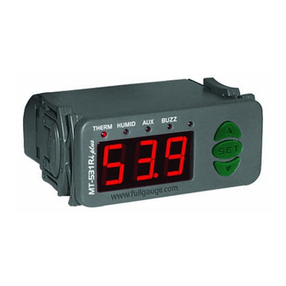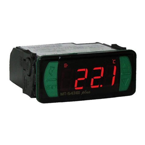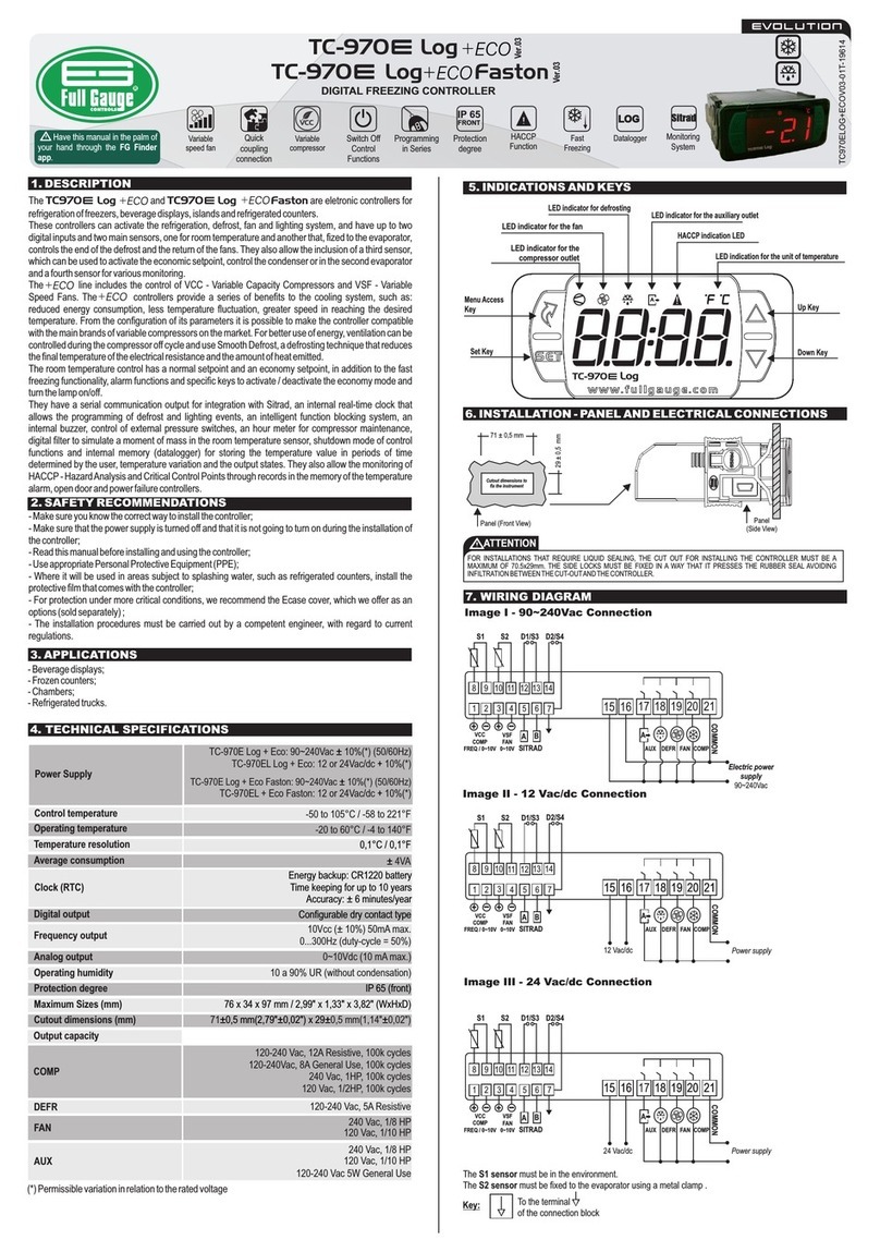
DESCRIPTION
FUN M NIMXAUNIT. DEFAULT
FUNCTION
CELSIUS (FAHRENHEIT)
[ ]s5
[ ]s4
[ ]s1
[ ]o5
[ ]s3
[ ]s2
[ ]o1
[ ]o2
[ ]o3
[ ]o4
This compensates for any deviations in the sensor reading due to replacement or a change
in cable length.
This compensates for any deviations in the sensor reading due to replacement or a change
in cable length. The sensor S2 can be disabled by setting the function to the minimum value
until the message appears. When disabled, all functions that depend on the reading[OF]
of sensor S2 are disabled.
The value adjusted in this function represents the time ( in seconds) for the displayed
temperature to change by 0.1°C (1°F) as the temperature rises or falls.
Note: A typical application for this type of filter is freezers (such as ice cream displays). As
the door is opened for short periods of time, hot air may directly hit the sensor, causing a
rapid increase in the measured temperature indication, and often unnecessarily activating
the compressor.
This is the duration of the ast Freezing processF
This is the minimum temperature the instrument can reach during the Fast Freezing.
-14 ( )7
ºC (°F)
- ( )11 12
ºC (°F)
- .0 ( )621
ºC (°F)
- .0 ( )326
ºC (°F)
099 5
hours
20
1
0 [of]
0
0 [of]
0
0 [of]0 [of] 20
seconds
-
seconds
-
0 [of] 1 [on] 0 [o ]f
-
0 [of] 1 [on] 1 [on]
-9.9 (-9) 9.9 (9) ºC (°F) 0. 00 ( )
-10 [of]
9.9 (9) ºC (°F) 0 0.0 ( )
Digital filter intensity applied to sensor S1
(Cabinet) (Rise)
Digital filter intensity appliced to sensor S1
(Cabinet) (Fall)
Offset of the Evaporator Sensor (sensor S2)
Offset of the cabinet sensor indication
(sensor S1)
Digital filter operating mode
Maximum ast reezing timeFF
[,0] = Electric defrost (electric heaters), only the defrost output is activated.
= Hot gas defrost, compressor and defrost outputs are activated.[,1]
= Natural defrost, only the fan output is actuated.[,2]
Defrost type
[d1] 02-0
[,0]= Defrost started by time
= Temperature-initiated defrost (sensor S2)[,1]
[,2]= Defrost initiated by temperature difference S1-S2
= Defrost initiated by and temperature difference S1-S2[,3] (sensor S2)
Defrost start condition
[d2] 03-0
Determines how often defrost will be performed, which is the time counted from the end of
the previous defrost. If the controller is configured to perform temperature defrost
( , or ), this time acts as safety in situations where the evaporator[d2] [1] [2] [3]=
temperature (sensor S2) does not reach the programmed values in or . This[d5] [d6]
function determines the maximum time the controller remains without defrosting.
It serves to increase the time interval to start the first defrost only. In multiequipment
installations, it is possible to avoid peaks in demand by not matching the defrost start time of
each equipment.
Note: Scale hours.minutes - time less than 10.0 displays decimal point. Ex: value 1.5
corresponds to 1 hour and 30 minutes.
Interval between defrosts if = or[d2] [,0]
Maximum time without defrost if = or[d2] [1] [2] [3],
Additional time at end of the first cooling cycle
Temp ture evap to start defrost ifera of orator
[d2] [1] [3]=or
Smooth Defrost
Low temperature confirmation time (sensor S2) to
initiate pre-defrost if =[d2] [1] [2] [3],ou
Temperature difference to start defrost (S1-S2) if
[d2] [2] [3]=or
Enable tray defrosting
[d3]
[d ]4
[d ]5
[ ]b1
[d ]7
[ ]b3
[ ]b4
[ ]b5
[d ]6
[ ]b2
[d ]8
ho .minut surs e
0.0 [of] 0.0 [of]
99
minu ste
0 [of]0 [of]
99
hours
199 12
°C (°F)
-50 (-58) 60 (99) -20 (-4)
-
110 [of] 10 [of]
minut se
1
99 10
°C (°F)
-50 (-58) 60 (99) 40 (99)
°C (°F)
-50 (-58) 60 (99) 20 (68)
°C (°F)
-50 (-58) 60 (99) 15 (59)
When the evaporator temperature (sensor S2) reaches the value configured in this
function, the controller starts the confirmation time count to start the defrost ( ).[d7]
When the difference between the cabinet temperature (sensor S1) and the temperature of
the evaporator (sensor S2) reaches the value configured in this function, the controller
starts confirmation time count to start the defrost ( ).[d7]
If the controller is configured to perform temperature defrost, at the moment the sensor S2
reaches the configured temperature value for defrost, then it starts for pre-defrost process.
If this temperature rises above the configured value, the system returns to the refrigeration
step.
Defrost when energizing the controller Enables defrosting at the moment that the controller is energized, such as when the power
returns (in case of power failure).
Smooth Defrost mode allows for a smoother defrost, saving energy and preventing the
room temperature from rising as much as a standard defrost. In this mode, the defrost
output remains on as long as the evaporator temperature (sensor S2) is less than 2°C
(36°F), as the temperature is superated the defrost output cycles between ON and OFF as
the percentage of time interval (2 min) configured in this function (x10). This mode is active
only if sensor S2 is enabled and electric defrost is enabled ( = ).[d1] [0]
When defrosting starts, the controller will activate only the fan during this time, in order to
harness the residual energy if = .[b2] [of]
With this function active, the FANS output tes as a second defrost output. Thisopera output
is triggered during pre-defrost, defrost and drainage.
Note: With = the fan control functionality is disregarded.[b2] [On]
Pre-defrost time (pump down)
If the temperature in the evaporator (sensor S2) reaches the set value, the end of the
defrost happens by temperature. It can optimize the defrost process.
Evaporator temperature (sensor S2) to end defrost
Cabinet temperature (sensor S1) to end defrost If cabinet temperature (sensor S1) reaches the configured value, the end of defrost
happens by temperature.
[ 2]H
[ 2]m
[ ]m1
[ ]H1 This is the difference between turning refrigeration OFF and BACK ON in normal ( )[H1]
or power save ( ) operating mode.[H2]
Defines if parameters and acts on the control or just on temperature display:[S2] [S3]
[0] =Acts on temperature display and on control routines
[1] =Acts only on temperature display
This is the control temperature when the economic operating mode is active. If the sensor
temperature S1 (cabinet) the value configured in this function, theless than or equal to
compressor turns OFF.
Limits designed to prevent unintentional temperatures from being configured by mistake
high or low temperature setpoint, which may result in high power consumption power for
keeping the system continuously on.
-50 (-58) -50 (-58)
M2
M1 60 (99) 60 (99)
ºC (°F)
ºC (°F)
0.1 (1) 3.0 (5)8.0 (14)
0.1 (1) 8.0 (14) 3.0 (5)
ºC (°F)
ºC (°F)
Minimum desired temperature (setpoint)
permited for the user
Maximum desired temperature (setpoint)
permited for the user
Control differential (hysteresis)
Power Save Control differential (hysteresis)
Desired Temperature (economic setpoint) (r1)
Desired Temperature (economic setpoint) (r2)
Desired Temperature (economic setpoint) (r3)
Desired Temperature (economic setpoint) (r4)
Temperature limit for ast reezing (r1)FF
Temperature limit for ast reezing (r2)FF
Temperature limit for ast reezing (r3)FF
Temperature limit for ast reezing (r4)FF
[ 2]e
[ ]e1
[ ]e4
[ ]e3
M1 M2
M1 M2
ºC (°F)
ºC (°F)
-4.0 (25)
-1.0 (30)
M1 M2
M1 M2
ºC (°F)
ºC (°F)
4. 390 ( )
745.0 ( )
This is the control temperature of the normal operating mode. When the temperature of
sensor S1 (cabinet) is the value configured in this function, theless than or equal to
compressor turns OFF.
M1 M2
M1 M2
M1 M2
M1 M2
ºC (°F)
ºC (°F)
ºC (°F)
ºC (°F)
-9.0 (16)
-6.0 (21)
-1.0 (30)
236.0 ( )
Desired Temperature (setpoint) (r1)
Desired Temperature (setpoint) (r2)
Desired Temperature (setpoint) (r3)
Desired Temperature (setpoint) (r4)
[t ]4
[t ]3
[t2]
[t ]1
6.5 Functions table
-50 (-58) 60(99)
-50 (-58) 60(99)
-50 (-58) 60(99)
-50 (-58) 60(99)
