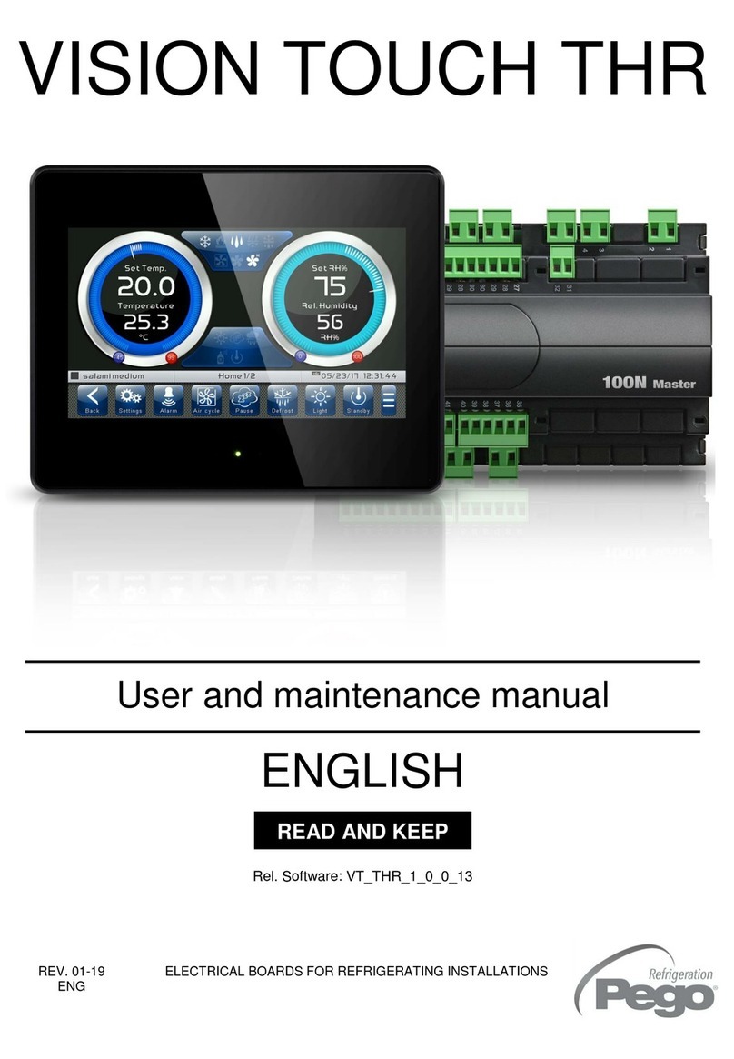
Pego Vision Touch Wellness Operating instructions

REV. 01/04
User and maintenance manual
ELECTRICAL BOARDS FOR REFRIGERATING INSTALLATIONS
READ AND KEEP
REL. 01-19
ENG
VISION TOUCH WELLNESS
ENGLISH
Rel. Software: VT_WEL_5_0_0_2

VISION TOUCH WELLNESS
Pag. 2
USER AND MAINTENANCE MANUAL
Rel 01-19
Thank you for choosing PEGO'S VISION TOUCH WEL controller.
Reading this manual thoroughly will guide you through proper installation and better use of
the various features. We therefore recommend keeping this manual near the controller to
make use of it during the device installation, configuration and use.
Waste disposal guidelines:
The Vision Touch controller consists of glass parts, plastic parts and metal parts.
With reference to the Directive 2012/19/EC of the European Parliament and of the Council
of 4 July 2012 and related national legislation, please note that:
A. There is the obligation not to dispose of WEEE as urban waste and to perform
separate collection of this waste.
B. Public or private waste collection facilities foreseen by local laws must be used to
dispose of the materials. It is also possible to give the device back to the distributor
at the end of its life when purchasing a new one.
C. This equipment can contain dangerous substances: improper use or incorrect waste
disposal could have negative effects on human health and on the environment.
D. The symbol (crossed-out waste bin on wheels) applied to the pack, product
and instructions indicates that the appliance was placed on the market after August
13, 2005, and must be disposed of separately.
E. In case of abusive disposal of electrical and electronic waste, there are sanctions
established by local standards in force concerning waste disposal.

VISION TOUCH WELLNESS
Pag. 3
USER AND MAINTENANCE MANUAL
Rel 01-19
INTRODUCTION
Page 5 1.1 General information
Page 6 1.2 Product identification codes
Page 7 1.3 Overall dimensions
Page 7 1.4 Identification data
Page 8 1.5 Technical features
INSTALLATION
Page 9 2.1 General rules for the installer
Page 9 2.2 Standard equipment for assembly and use
Page 10 2.3 Installation and assembly
ELECTRICAL CONNECTIONS
Page 12 3.1 Console / 100N MASTER3 power supply and connection
Page 14 3.2 Connection of digital outputs on 100N MASTER3
Page 15 3.3 Connection of digital inputs on 100N MASTER3
Page 16 3.4 Connection of analogue inputs on 100N MASTER3
Page 17 3.5 Connection of analogue outputs on 100N MASTER3
Page 18 3.6 Connection to RS-485 for TeleNET or Modbus- RTU
SWITCHING ON
Page 19 4.1 Commissioning
Page 20 4.2 Switch-on controller
USER INTERFACE
Page 21 5.1 Console functional zones
Page 22 5.2 Main display
Page 22 5.3 Status bar
Page 23 5.4 Button bar
Page 25 5.5 Gesture
HOME PAGES
Page 29 6.1 HOME 1 –Temperature / Humidity, I/O status management
Page 32 6.2 HOME 1 –Temperature / Humidity Set point Modification
Page 33 6.3 CHROMOTHERAPY
Page 34 6.4 HOME 2
Page 34 6.5 HOME 2 –Scheduled switch-on
Page 35 6.6 HOME 2 –Scheduled switch-off
Page 36 6.7 HOME 2 –Weekly programmable thermostat
ACCESS LEVELS
Page 38 7.1 Access levels to parameters (User / installer)
Page 38 7.2 Lock screen and User / installer login
CONTENTS
CHAPTER 1
CHAPTER 2
CHAPTER 3
CHAPTER 4
CHAPTER 5
CHAPTER 6
CHAPTER 7

VISION TOUCH WELLNESS
Pag. 4
USER AND MAINTENANCE MANUAL
Rel 01-19
PARAMETERS
Page 39 8.1 Access to the “Parameters” menu
Page 40 8.2 Description of parameters setting page
Page 41 8.3 Parameters menu items list
Page 43 -8.3.1 Process adjustment
Page 44 -8.3.2 Air change
Page 44 -8.3.3 Configure WELLNESS
Page 45 -8.3.4 Machine protection
Page 45 -8.3.5 Probes calibration
Page 46 -8.3.6 Configuration RS485
Pag. 47 -8.3.7 Web server
Pag. 51 -8.3.8 Mail
Page 52 -8.3.9 Humidifier PEGO
Page 53 -8.3.10 RGB
Page 53 -8.3.11 Language
Page 54 -8.3.12 Date and time
Page 55 -8.3.13 General settings
Page 56 -8.3.14 Software
Page 57 -8.3.15 Info
Page 58 -8.3.16 Password
Page 60 -8.3.17 Test center
Page 65 -8.3.18 Configure I/O
Page 70 -8.3.19 I/O status
DIAGNOSTICS
Page 71 9.1 Diagnostics
Page 73 9.2 PEGO humidifier’s diagnostics
Page 75 9.3 Alarms management
Page 76 9.4 Pop-up management
WEB SERVER
Pag. 77 10.1 Installation
Pag. 79 10.2 Interfaccia web: accesso utente
Pag. 80 10.3 Interfaccia web: pagine
OPERATION
Page 88 11.1 WELLNESS configuration: Sauna
Page 88 11.2 WELLNESS configuration: Wet sauna
Page 89 11.3 WELLNESS configuration: Turkish bath
Page 90 11.4 New software features
ACCESSORIES
Page 91 12.1 400SAUNASENS
APPENDICES
Page 92 A.1 EU Declaration of Conformity
Page 93 A.2 Warranty terms
CHAPTER 8
CHAPTER 9
CHAPTER 11
CHAPTER 12
CHAPTER. 10

VISION TOUCH WELLNESS
Pag. 5
USER AND MAINTENANCE MANUAL
Rel 01-19
GENERAL INFORMATION
DESCRIPTION:
The VISION TOUCH WELLNESS allows for advanced management of saunas, steam
rooms and Turkish baths.
The system consists of the 100N MASTER3 unit, on which all the electrical connections
are made, and the VISION TOUCH WEL control console, equipped with 7'' TFT display
with capacitive touch screen combined with a highly advanced software and a highly user
friendly interface that allows easy use.
APPLICATIONS:
-Saunas.
-Wet saunas.
-Turkish bath (only with combined Easysteam humidifier).
TECHNICAL SPECIFICATIONS FOR WELLNESS:
-Manual or automatic switch-on (by setting a single time or with weekly programmable
thermostat)
-Drying cycle configurable at the end of the operating period (only ventilation or
ventilation and heating).
-Maximum settable time of operation up to 12 hours.
-Temperature regulation range: 0°C/+99°C.
-Humidity regulation range: 0-100 R.H.%, with a maximum programmable value in
accordance with standard EN60335-2-53:2012.
-Internal light control.
-RGB light control (Chromotherapy, requires external controller).
For appliances for use in blocks of flats, hotels and similar locations, the
operating period of the sauna heater shall be limited to 12 h with a minimum rest
period of 6 h before any automatic restarting. For other appliances, the
operating period of the timer shall be limited to 6 h, automatic restarting not
being allowed (reference to standard EN60335-2-53:2012, section 22.103).
CHAPTER 1: INTRODUCTION
CAP. 1 - Introduzione
1.1

VISION TOUCH WELLNESS
Pag. 6
USER AND MAINTENANCE MANUAL
Rel 01-19
GENERAL CHARACTERISTICS OF THE CONTROLLER:
-7'' TFT display with high resolution (800x480 WVGA), LED backlighting and capacitive
touch screen.
-Front with 1,1mm chemically treated glass.
-Ability to reverse the viewing angle of the display to ensure the possibility of mounting
at any height.
-Devices: USB 2.0, microSD, RS485.
-Acoustic signals.
-IP65 frontal protection.
-High quality design and icons.
-Touch screen interface with gestures, for an even more intuitive control.
-Clock and calendar (RTC).
-Password function.
-Multilingual.
-Customizable user parameter menu (unused features can be hidden, simplifying the
menu).
-Contextual help in the parameter configuration menu.
-Software updating from microSD or USB.
-Ability to export and import parameters on USB or microSD media.
-Alarm history combined with popup warning messages.
-Detailed memory of temperature / humidity alarms triggered.
-"Test center" mode to check, in a simple and intuitive way, all the digital and analogical
inputs/outputs.
-RS485 serial connection with TeleNET or Modbus protocol which can be selected in
the parameters.
-Web server: control the Vision Touch from web browsers (controlled access).
-Automatic sending of e-mail in case of alarm.
PRODUCT IDENTIFICATION CODES
200VT100WEL1 - TOUCH electronic control dedicated for
wellness applications. It has a stylish 7'' TFT
display with capacitive touch screen combined
with a highly advanced software and a highly
user friendly interface that allows for easy use.
- 5m telephone cord included.
- 1 NTC probe (1x1.5 m) included.
Humidity probe is separate.
1.2

VISION TOUCH WELLNESS
Pag. 7
USER AND MAINTENANCE MANUAL
Rel 01-19
OVERALL DIMENSIONS
Dimensions in mm:
IDENTIFICATION DATA
The device described in this manual has, on the side of 100N MASTER3 and on the back
of the VISION TOUCH WELLNESS console, a plate bearing its identification data:
• Name of Manufacturer
• Description anche code of device
• Serial number of device
• Date of manufacture
VISION TOUCH
100N MASTER3
1.3
1.4

VISION TOUCH WELLNESS
Pag. 8
USER AND MAINTENANCE MANUAL
Rel 01-19
TECHNICAL FEATURES
Power supply
Voltage
110 - 230 V~ 10% 50/60Hz
Max power consumption (electronic controller only)
~ 15 VA
Climatic conditions
Operating temperature
-5 ÷ +50°C
Storage temperature
-10 ÷ +70°C
Relative ambient humidity
Less than 90% RH
General features
Type of connectable probes (temperature)
NTC 10K 1%
Resolution (ambient temperature)
0.1°C
Precision of probe detection (ambient temperature)
± 0,5°C
Reading range
-45 ÷ +99 °C
Humidity probe
analogue input 4-20 mA
Precision of humidity probe detection
see humidity probe features
Range of humidity probe detection
0-99 rH%
Output features
Description
Relay installed
Features of output board
Notes
Output 3-4
(30A AC1 relay)
30A 240V~(AC1)
10A 240V~(AC3) (2HP)
(100000 cycles)
All the outputs are
voltage-free
contacts
11 outputs from 5 to 26
(see connections diagram)
(16A AC1 relay)
16A 240V~(AC1)
3A 240V~(AC3)
Dimensional features
Dimensions 100N MASTER
121.50 mm x 71 mm x 175 mm (HxDxL)
Dimensions VISION TOUCH
151 mm x 44 mm x 191 mm (HxDxL)
Insulation and mechanical properties
Degree of protection of display
IP65
Material of box
Self-extinguishing ABS
1.5

VISION TOUCH WELLNESS
Pag. 9
USER AND MAINTENANCE MANUAL
Rel 01-19
GENERAL RULES FOR THE INSTALLER
1. If the program is used in applications with the risk of harming persons, machines or
materials, it must be coupled with auxiliary alarm devices;
2. The programmer must NOT be installed in environments with dangerous atmospheres
(flammable or explosive); it can only be connected to elements which operate in this
atmosphere by means of appropriate and suitable types of interface compliant with
safety standards in force;
3. Install the appliance in places which respect the degree of protection;
4. Avoid using multi-pole cables with conductors connected to inductive and power
conductors and signal conductors like probes and digital inputs;
5. Avoid housing power cables in the same conduits as signal cables (probes, digital or
analogue inputs, communication cables)
6. Minimize the length of the connecting cables to prevent these from coiling up and
adversely affecting the electronics through induction;
7. All the conductors of the cables must be of an appropriate size to withstand the required
load;
8. Place a general protection fuse upstream the electronic controller;
9. Provide a two-phase disconnecting switch compliant with foreseen safety requirements
(CE marked) to shut off the power supply upstream the controller. The switch must be
placed in the immediate vicinity of the regulator and must be easily reachable by the
operator.
10. Should the length of the probes need to be extended, it is necessary to use conductors
with an appropriate cross-section and however no less than 1mm². Extension or
shortening of the probes may alter the factory settings; use an external thermometer,
therefore, for testing and calibration.
11. When using the console at low temperatures there could be a visible slow down in the
response from the display; this can be considered normal.
STANDARD EQUIPMENT FOR ASSEMBLY AND USE
The VISION TOUCH WELLNESS electronic controller is provided with the following for
assembly and use:
• 1 temperature probe;
• 1 plug telephone cable (5m);
• 1 user quick guide;
• 1 consolle Vision Touch WELLNESS (200VTOUCHWEL);
• 4 media for Vision Touch console;
• 1 100N MASTER3 (200100NMSTH3);

CHAPTER 2: INSTALLATION
2.2
2.1

VISION TOUCH WELLNESS
Pag. 10
USER AND MAINTENANCE MANUAL
Rel 01-19
INSTALLATION AND ASSEMBLY
Fig. 1: Install the 100N MASTER3
module on the DIN guide and
close the bottom clamps to hold
it in place.
Fig. 2: VISION TOUCH console drilling
template.
Fig. 3: Configure properly the side
switch (if present) to reverse the
viewing angle of the display. This
allows you to mount the VISION
TOUCH at any height.
When mounted in the low
position, rotate the display by
180° in order to have the signal
leds at the top.
177mm
136mm
2.3

VISION TOUCH WELLNESS
Pag. 11
USER AND MAINTENANCE MANUAL
Rel 01-19
Fig. 4: Fasten the VISION TOUCH
console by means of the four
media to be inserted in their
specific seats.
Tighten each screw until the
entire border front of the console
rests on the panel.

VISION TOUCH WELLNESS
Pag. 12
USER AND MAINTENANCE MANUAL
Rel 01-19
Following are the electrical connections of the controller divided by type. The
configurations of the inputs and outputs shown below are set by default but can be
changed to suit your needs. The connection between the console and 100N MASTER3
has two possible variants based on the distance between the two components.
POWER SUPPLY AND CONNECTION CONSOLE / 100N MASTER3
1) Connection between the console and 100N MASTER3 with distance within 10m:
CHAPTER 3: ELECTRICAL CONNECTIONS
3.1
Power
supply
Connect the ground to the GND
terminal of M2 in the console
(functional ground).
This connection helps to limit the
effects of the electromagnetic
noise on the control system.
The earth connection must be
made in a manner consistent with
applicable regulations.
Connect the power to terminals 1
and 2 of 100N MASTER3.
Switching power supply:
115÷230Vac ±10% 50/60 Hz
Demand: 20 VA max.
.
Use the supplied telephone cord
and connect the 8-pin Plugs to
J1in the console and to J1 in the
100N MASTER
(it includes communication and
power).

VISION TOUCH WELLNESS
Pag. 13
USER AND MAINTENANCE MANUAL
Rel 01-19
2) Connection between the console and 100N MASTER3 with distance within
500m:
Power
supply
Connect the ground to the GND
terminal of M2 in the console
(functional ground).
This connection helps to limit the
effects of the electromagnetic
noise on the control system.
The ground connection must be
made in a manner consistent with
applicable regulations.
Connect the power to terminals 1
and 2 of 100N MASTER3.
Switching power supply:
115÷230Vac ±10% 50/60 Hz
Demand: 20 VA max.
.
Connect terminal (-) of M1 in the
console to terminal 45 of 100N
MASTER3 and term (+) of M1 in
the console to terminal 46 of
100N MASTER3.
Avoid coupling with power cables.
Connect terminal (1) of M2 in the
console to terminal 37 of 100N
MASTER3 and term (B) of M2 in
the console to terminal 38 of
100N MASTER3.
Connect the braid of the shielded
cable to the (GND) terminal of
M2in the console. Use twisted
cable suitable for the transmission
of RS485 signals with minimum
section of 0.5mm2(e.g. Belden
8762 cable). Avoid coupling with
power cables.

VISION TOUCH WELLNESS
Pag. 14
USER AND MAINTENANCE MANUAL
Rel 01-19
DIGITAL OUTPUT CONNECTION ON 100N MASTER3
PIN
TERMINALS
DIGITAL
OUTPUT
DEFAULT SETTINGS
DIGITAL OUTPUTS
RELAY OUTPUT FEATURES
(Voltage-free contacts)
3-4
DO1
1 = Hot 1
(contact N.O)
Relay 30A 240V~ (AC1)
10A 240V~ (AC3) (2HP)
5-6
DO2
2 = Hot 2
(contact N.O)
Relay 16A 240V~ (AC1)
3A 240V~ (AC3)
7-8
DO3
3 = Hot 3
(contact N.O)
Relay 16A 240V~ (AC1)
3A 240V~ (AC3)
9-10
DO4
4 = Fans
(contact N.O)
Relay 16A 240V~ (AC1)
3A 240V~ (AC3)
11-12
DO5
5 = Humidification
(contact N.O)
Relay 16A 240V~ (AC1)
3A 240V~ (AC3)
13-14
DO6
6 = Light
(contact N.O)
Relay 16A 240V~ (AC1)
3A 240V~ (AC3)
15-16
DO7
R
G B
7 = RGB Light
(contact N.O)
Relay 16A 240V~ (AC1)
3A 240V~ (AC3)
25-26
DO8
0 = Disabled
Relay 16A 240V~ (AC1)
3A 240V~ (AC3)
23-24
DO9
0 = Disabled
Relay 16A 240V~ (AC1)
3A 240V~ (AC3)
21-22
DO10
0 = Disabled
Relay 16A 240V~ (AC1)
3A 240V~ (AC3)
19-20
DO11
0 = Disabled
Relay 16A 240V~ (AC1)
3A 240V~ (AC3)
17-18
DO12
12 = Alarm
(contact N.O)
Relay 16A 240V~ (AC1)
3A 240V~ (AC3)
POSSIBLE CONFIGURATIONS
DIGITAL OUTPUTS DO1÷DO12
Access menu:
Parameters > Configure I/O > Digital
outputs
0 = Disabled
1 = Hot 1
2 = Hot 2
3 = Hot 3
4 = Fans
5 = Humidification
6 = Light
7 = RGB Light
8 = Alarm (only DO12)
Positive values = Contact N.O.
Negative values = Contact N.C.
3.2

VISION TOUCH WELLNESS
Pag. 15
USER AND MAINTENANCE MANUAL
Rel 01-19
DIGITAL INPUT CONNECTION ON 100N MASTER3
PIN
TERMINALS
DIGITAL
INPUT
DEFAULT SETTINGS DIGITAL INPUTS
(Use voltage-free contacts)
47-59
DI1
-1 = Alarm (function Not active with contact N.C.)
48-59
DI2
2 = Stand-by from remote (function Not active with contact N.O.)
49-59
DI3
3 = Disable hot (function Not active with contact N.O.)
50-59
DI4
4 = Disable humidity (function Not active with contact N.O.)
51-59
DI5
5 = Humidifier alarm (function Not active with contact N.O.)
52-59
DI6
6 = Fans protection (function Not active with contact N.O.)
53-59
DI7
7 = Generic Warning 1 (function Not active with contact N.O.)
54-59
DI8
8 = Generic Warning 2 (function Not active with contact N.O.)
55-59
DI9
9 = Generic Warning 3 (function Not active with contact N.O.)
56-59
DI10
0 = Disabled
57-59
DI11
0 = Disabled
58-59
DI12
0 = Disabled
POSSIBLE CONFIGURATIONS
DIGITAL INPUTS DI1÷DI12
Access menu:
Parameters > Configure I/O > Digital inputs
0 = Disabled
1 = Alarm
2 = Stand-by
3 = Disable hot
4 = Disable humidity
5 = Humidifier alarm
6 = Fans protection
7 = Generic Warning 1
8 = Generic Warning 2
9 = Generic Warning 3
Positive values = Contact N.O.
Negative values = Contact N.C.
3.3

VISION TOUCH WELLNESS
Pag. 16
USER AND MAINTENANCE MANUAL
Rel 01-19
ANALOGUE INPUT CONNECTION ON 100N MASTER3
PIN
TERMINALS
DESCRIPT.
TERMINALS
TYPE OF
SIGNAL
ANALOGUE
INPUT
DEFAULT SETTINGS
ANALOGUE INPUTS
DEFAULT SETTINGS
BRIDGES ON
100N MASTER3
27
RH
4-20mA
AI1
2 = Ambient humidity
probe
J11 = 2-3
J12 = 1-2
J13 = open
28
V+
29
NTC
AI2
1 = Ambient temperature
J21 = 1-2
J22 = 2-3
J13 = open
30
31
NTC
AI3
0 = Disabled
J31 = 1-2
J32 = 2-3
J33 = open
32
33
NTC
AI4
0 = Disabled
J41 = 1-2
J42 = 2-3
J43 = open
34
35
NTC
AI5
0 = Disabled
J51 = 1-2
J52 = 2-3
J53 = open
36
POSSIBLE CONFIGURATIONS
ANALOGUE INPUTS AI1÷AI5
Access menu:
Parameters >Configure I/O >Analogue inputs
0 = Disabled
1 = Ambient temperature (NTC)
2 = Ambient humidity probe (4-20mA)
The selection of the desired function for each analogue
input is done by the configuration of the dedicated
parameter in the “Parameters > Configure I/O >
analogue inputs” menu combined with the correct
setting of the Hardware configuration jumpers on the
100N MASTER3 under the removable front cover (see
the side image).
In particular, the configuration is as follows:
For NTC probes: J*1=1-2, J*2=2-3, J*3=open
For 4-20mA probes: J*1=2-3, J*2=1-2, J*3=open
*= number analogue input
3.4

VISION TOUCH WELLNESS
Pag. 17
USER AND MAINTENANCE MANUAL
Rel 01-19
ANALOGUE OUTPUT CONNECTION ON 100N MASTER3
PIN
TERMINALS
DESCRIPT.
TERMINALS
TYPE OF
SIGNAL
ANALOGUE
OUTPUT
DEFAULT SETTINGS
ANALOGUE OUTPUTS
41
Ref.
0-10V
AO1
1 = RGB light control –red
44
Gnd
42
Ref.
0-10V
AO2
2 = RGB light control –green
44
Gnd
43
Ref.
0-10V
AO3
3 = RGB light control –blue
44
Gnd
ETHERNET CONNECTION ON VISION TOUCH
POSSIBLE CONFIGURATIONS
ANALOGUE OUTPUTS AO1÷AO3
Access menu:
Parameters>Configure I/O>analogue outputs
0 = Disabled
1 = RGB light control - red
2 = RGB light control - green
3 = RGB light control - blue
3.5
Connect the Ethernet cable with
RJ45 connector to the J3 input of the
Vision Touch console. Connect the
other end of the cable to the existing
LAN or to the PC.
3.6

VISION TOUCH WELLNESS
Pag. 18
USER AND MAINTENANCE MANUAL
Rel 01-19
CONNECTION TO RS-485 FOR TELENET OR MODBUS-RTU
1) Example of connection between the console and the Modbus line:
It is recommended to connect a resistor equal to 120between A and B at the beginning
and end of the line in case of communication problems.
For a correct functioning the Master has to have a RS485 polarized.
3.7
Connect the earth to the GND
terminal of M3 in the console
(functional earth).
This connection helps to limit the
effects of the electromagnetic
noise on the control system.
The ground connection must be
made in a manner consistent with
applicable regulations.
Connect the terminal (A) of M3 in
the console to signal A of the
Modbus line and the terminal (B)
of M3 in the console to signal B of
the Modbus line. Connect the
braid of the shielded cable to the
terminal (GND) of M3 in the
console.
Use twisted cable suitable for the
transmission of RS485 signals
with minimum section of 0.5mm2
(e.g. Belden 8762 cable). Avoid
coupling with power cables.

VISION TOUCH WELLNESS
Pag. 19
USER AND MAINTENANCE MANUAL
Rel 01-19
COMMISSIONING
When the controller is switched on for the first time, the "Language Selection" and "time
and date setting" pages of the system are displayed to facilitate the user in starting up the
controller. These settings can even be modified further on by means of the "Language"
and "Date and time" items within the "Parameters" menu.
4.1
CHAPTER 4: SWITCHING ON
Confirm the
settings by
pressing the
confirmation
button.
Set the date
and time by
scrolling your
finger over the
digits from the
top
downwards.
Set the
language by
pressing these
buttons.
Confirm the
settings by
pressing the
confirmation
button.
Automatic date
and time
synchronization
via the Web
(required ethernet
connection)

VISION TOUCH WELLNESS
Pag. 20
USER AND MAINTENANCE MANUAL
Rel 01-19
SWITCH-ON CONTROLLER
Every time the controller is switched on, an information pop-up is displayed with the
starting date and time, requesting the user to acquire the information by pressing "OK".
This allows to verify the return from an electrical blackout.
The start-up event is also memorized inside the "alarms" menu to make it possible to verify
this information over time.
4.2
Information
acquisition
button.
Controller
starting date
and time.
Device power on
Begin: 18-04-2015 13:45:24
Table of contents
Other Pego Controllers manuals

Pego
Pego EasySteam 400HUM2ESXX User manual

Pego
Pego 200NDINFSC Operating instructions

Pego
Pego PLUS 200 2 PLT User manual

Pego
Pego 200PEVS01 Operating instructions

Pego
Pego ECP200 Expert d7.5 User manual

Pego
Pego ECP200 BASE Series User manual

Pego
Pego VISION TOUCH THR Operating instructions

Pego
Pego ECP200 Expert d7.5 User manual

Pego
Pego ECP200 Expert d7.5 User manual

Pego
Pego VISION SC600 User manual