E&P HYDRAULICS LEVEL SYSTEM User manual

›English - Electronic Levelling System
Assembly Manual

70
›Contents
Foreword Page 71
Scope of delivery Page 72
Assembly is carried out in eight stages
1. Fitting the corner supports Page 73
2. Fitting the axle supports Page 75
3. Installing the pump Page 77
4. Laying the pipework Page 78
5. Installing the electronics Page 81
6. Taking the system into service Page 82
7. Programming the zero point Page 83
8. Finishing and maintenance of the installation Page 84
Five tips for the customer Page 84
Layout of the hydraulic pipework Page 85
General Terms and Conditions of Trade Page 86
Order list for the axle brackets Page 87

71
›Foreword
“Products must be 100% user-friendly and reliable”: that is the strategic vision of E&P Hydraulics, who
designed this levelling system.
But this philosophy doesn’t apply just to the customer; the fitters who install the system at our dealers
are of extreme importance to us as well. The quality of our products stands and falls with their being
installed professionally. That’s why E&P makes every effort to support its system fitters in all respects.
These installation instructions are one important reflection of this policy. In eight different steps, we
show how this system can be installed as well and as effectively as possible.
Naturally, this doesn’t mean that installing an E&P levelling system is an easy matter. For the installation
of this system, a high level of specialist knowledge is called for, as this is an item of equipment subject
to considerable forces, which are frequently underestimated by people without a corresponding
technical background. If installed without the necessary expertise, extensive damage may be caused
in a flash, to say nothing of personal injury. This is why the system may only be installed by properly-
trained fitters with extensive practical experience and who have been trained in this particular field. The
fitters themselves remain at all times responsible for the installation of the system.
This document is based on the findings gathered from countless hours of tests and successful
installation processes. The materials supplied are all together designed to ensure the easiest possible
installation of the system. Ninety percent of the activities are carried out underneath the caravan, in
other words, at floor level.
When you work your way through these instructions step by step, you will realise just what a high quality
and at the same time user friendly product the E&P levelling system really is. There are nonetheless
still features which are capable of improvement. Therefore if you have any suggestions, comments
or questions on these instructions, or on the product itself, it is possible for you to contact us by
telephone.
E&P Hydraulics,
Eric Klinkenberg & Pierre Blom

72
›Scope of delivery
Every set comprises three separate cartons, in which all the components are contained:
1 Pump including control unit (black box)
2 Four different corner supports
3 Two axle supports
4 Two adapters for the axle supports
(including container with the corresponding fixing materials)
5 Fuse-holder for battery and fuse (container 3)
6 Electric cable with four-pin plug
7 Nine numbered hydraulic pipes
a) Two type 2 hoses (for the axle supports)
b) Two type 2R hoses (for the return from the axle supports)
c) One type 3 hose (for the rear corner supports)
d) One type 3R hose (for the return from the rear corner supports)
e) One type 4 hose (for the front corner supports)
f) One type 4R hose (for the return from the front corner supports)
g) One type 5R hose (intermediate hose pump-crosspiece)
8 Fixing material for the hydraulic pipework
9 Six distributors for the hydraulic hoses
a) four T-pieces with three male threads.
b) one T-piece with two male threads and one union nut
c) one crosspiece with four male threads
10 Control unit including holder bracket
11 Eight aluminium plates for mounting the corner supports.
12 Further fixing material (nuts, bolts and screws)

73
›STEP 1 Fitting the corner supports
First of all, remove the corner supports already fitted. Identify the type of the old corner supports. If
the corner supports are of the AL-KO brand, then the new supports can be fitted in the same place in
the same way, and the chassis will not affect the fitting greatly.
With reference to the BPW brand, the existing cut-outs will always be suitable for fitting the replacement
supports. However, on caravans with dismounted BPW- supports, the chassis will be in the way, as
at one point on the support, the frame prevents the support being completely withdrawn. It will be
essential to find a solution for this problem.
Please make sure that in all cases and for all types of corner supports removed, the aluminium cylinder
can carry out its complete movement and does not press against the chassis. The power of the system
must not be allowed to work against the wrong points.
!! The new corner supports are all different, and the studs are located in mirror image with respect to
the corner supports. You will find details of the corner supports (front left, front right, rear left and
rear right) on a small sticker on the guide rails of the corresponding products.
Now fix the new supports in their corresponding positions, using two M8 bolts. Do not forget to place
the two aluminium spacers on the M8 drill-holes. When fixing the new corner supports, make sure to
bond the aluminium guide rails solidly to the base. Use the right adhesive for this, which means do not
use silicone. Degrease the rails as well as the areas where the guide rails are mounted, and allow the
glue to dry adequately before taking the system into service, although the aluminium guide rails will
also be fixed with the three steel set-screws supplied. The first hole (on the top edge, see arrow on the
following photograph) is directly visible. The other two holes will be seen when the support is extended,
but this can only be done when the system is being bled.
Proper fixing of the guide rails is an extremely important step, as very great stresses can be imposed
here extremely quickly.

74
›STEP 1 Fitting the corner supports
1. Removal of the old corner supports
2. Degreasing the floor and the new corner supports
3. Apply adhesive (e.g. Sika 221) to the top surface of the aluminium guide-rails for the new corner
supports. Do not forget to apply to the two aluminium filler plates.
4. Fully tighten one of the three fixing screws.
8
Schritt1
1.DemontagederaltenEckstützen
2.EntfettendesBodensundderneuenEckstützen
3.Kleber(z.B.:Sika221)anderOberseitederAluminium-Laufschieneder
neuenEckstützenauftragen.DabeidürfendiebeidenFüllplattenaus
Aluminiumnichtvergessenwerden.
4.FestzieheneinerderdreiBefestigungsschrauben.
1
3
2
4

75
›STEP 2 Fitting the axle supports
When the system was ordered, you advised us of the make and type of caravan chassis to which our
system was to be fitted. Messrs. E&P Hydraulics have suitable adapters available for different caravan
types, and the correct adapter for your purposes was correspondingly supplied. If you still have
problems when positioning the adapter because the brackets do not fit, please make sure by reference
to the overview on Page 87 of these instructions that you have in fact been supplied with the correct
adapter.
If the caravan to which our system is to be fitted is a single-axle type, the fixing bracket must be
mounted so that the support is located behind the axle. If it is a tandem model, the cylinder must be
mounted on the rear axle, but facing forwards.
This will prevent the supports later on being subjected to an incorrect weight distribution. The axle
supports must be mounted as far away from the centre-line as possible, and you must also make sure
that the cylinder does not foul anything.
Fitting the axle supports
9
2.MontagederAchsstützen
SCHRITT2
BeiderBestellunghattenSieunsdieMarkeunddenTypdesChassisdesCaravans
genannt,andemunserSystemmontiertwerdensoll.DerFirmaE&PHydraulicsstehen
füralleCaravantypendiepassendenAdapterzurVerfügungundderfürihreZwecke
vorgesehenenAdapterwurdeentsprechendmitgeliefert.WennbeiderPlatzierungder
AdaptertrotzdemProblemeentstehen,dadieBügelnichtpassen,soinformierenSiesich
bitteinderÜbersichtaufSeite.....dieserAnleitung,obSieüberdiepassendenAdapter
verfügen.WennderCaravan,dermitunseremSystemversehenwerdensoll,nurübereine
einzigeAchseverfügt,müssenSiedenBügelsomontieren,damitsichdieStützehinter
derAchsebendet.HandeltessichumeinTandem-Modell,dannmussderZylinderan
derhinterenAchsemontiertwerden.Aberso,dassernachvornezeigt.Dadurchwird
vermieden,dassdieStützendasGewichtspäterineinemfalschenVerhältnisaufnehmen.
DieAchsstützenmüssennachMöglichkeitsoweitesgehtnachAussenmontiertwerden.
AchtenSiebittedarauf,dassderZylindernirgendwoanstösst.
MontagederAchsstütze

76
›STEP 2 Fitting the axle supports
Now clamp the adapter to the axle, but do not tighten the screws completely just yet, as you can still
adjust the position of the adapter by the amount that the axle supports are out of place due to the
bolts being too far apart. Thus the bolts should initially be partly tightened and then the axle supports
fitted at a height of about 12.5 cm (5”) from the ground. After this, the bolts are fully tightened. Finally,
check that the axle supports hang vertically and are inclined neither inwards nor outwards, nor to front
or rear.
!! Warning: Fixing the supports is probably the most important step of all in fitting the E&P
levelling system and therefore suitable expertise in this field is indispensable. The forces which act
on the system and the caravan must in no circumstances be underestimated. Do not drill any holes
in the chassis, and contact the dealer in all other cases of uncertainty, as the fitter himself is always
responsible for the installation of the system.

77
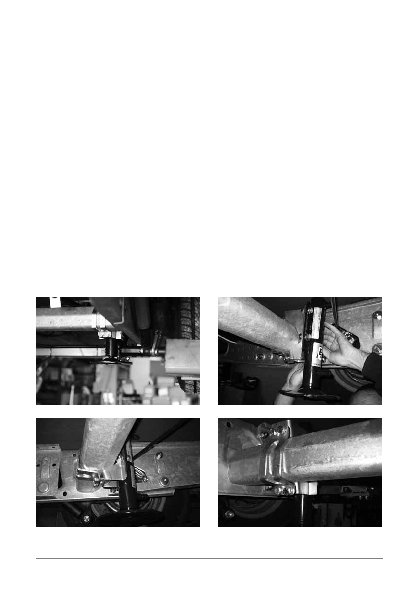
›STEP 3 Laying the pipework
Take the pump unit and unscrew the cap. Seek a suitable position for the pump with its cap removed
under the caravan floor. Make sure that the pipework connections point towards the rear and that the
fitting is mounted at a right-angle (parallel to the axle).
!! This is important to allow the controls to function properly.
The pump must be located as closely as possible behind the rear axle and with respect to the width
as close to the middle as possible. The purpose of this is to make optimum use of the length of the
pipework supplied, which is above all important in long caravans.
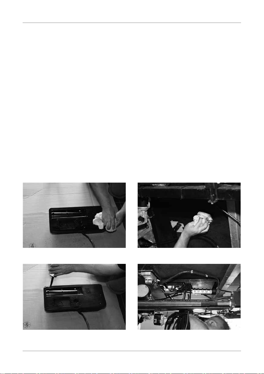
Before it is installed, the pump must have adhesive applied all the way round in the groove provided.
In addition, a strip of adhesive must be added in the middle directly underneath the control as this is
important for the control. To avoid malfunctions, the pump must stand level and the floor next to the
control absorb the load over the entire surface. Bonding the pump unit is absolutely essential. After
bonding, the container must be fixed with a total of nine bolts.
11
3.MontagederPumpe
SCHRITT3
NehmenSiediePumpeneinheitundschraubendenDeckelab.SuchenSienacheiner
geeignetenStellefürdiePumpe(beiderdieKappeentferntist)aufdemBodendes
Caravans.SorgenSiedafür,dassdieAnschlüssederLeitungennachhintenstehenund
dieAnlagerechtwinklig(parallelzurAchse)montiertwird.Diesistwichtig,damitdie
Steuerungordnungsgemäßfunktioniert.DiePumpemusssichsodichtwiemöglichhinter
derHinterachsebendenundauchinBezugaufdieBreitesogeringwiemöglichausder
Mitteherausragen.DiesdientdemZweck,dieLängedermitgeliefertenLeitungenoptimal
nutzenzukönnen.DiesistvorallembeilangenCaravanswichtig.
DiePumpemussvorihrerInstallationringsumindendafürvorgesehenenRandgeklebt
werden.ZudemmusseinStreifenKleberinderMittedirektunterderSteuerunggegeben
werden,denndiesistfürdieSteuerungwichtig.ZurVermeidungvonStörungenmussdie
PumpeebenstehenundderBodenbeiderSteuerungdieLastüberdievollständigeFläche
aufnehmen.DasklebenderPumpeneinheitistunbedingterforderlich.BefestigenSieden
Behälternachdemklebenmitinsgesamt9Schrauben.
Entfettendespumpgehäuses EntfettendesBodens
KlebendesPumpgehäuses MontagedesPumpgehäuses
Degreasing the pump housing
Bonding the pump housing
Degreasing the floor
Fitting the pump housing

78
›STEP 4 Laying the pipework
Now all components are fixed in place and the pipework can be laid. Use the nine separate pieces
of hose, the six distributors, and the fixing materials supplied for fitting the hoses in their appointed
places.
!! Please note: all cylinders are already filled with oil, so make sure they do not drain out and that
the hoses do not hang downwards. The quantities of oil have been carefully measured so that the
system does not need bleeding. If an unexpected leak does occur (more than 5 cc), please contact
Messrs. E&P.
!! Possible intermediate step. For unusual situations, we have developed an extension set.
In principle, all the hydraulic hoses are of a sufficient length for all standard types of caravan. For non-
standard situations in which a length greater than the standard pipework of 8 m is needed, E&P offers
you a special extension set. This set comprises two ready-to-use hoses (including the corresponding
couplings) with an overall length of 1000 mm each. If this length is still insufficient, further extension
sets can be ordered to obtain the necessary length of pipes.
Please refer to the layout shown on Page 85. Begin laying the hoses from the pump and make sure
that there are no kinks in the hoses, as every kink is associated with a marked weakening of the
system.
!! Please note: particular attention should be paid to the couplings on the corner supports; please
ensure that the hoses cannot possibly be squashed by the corner supports when the system is in
operation.
First of all, screw the T-piece with the number b (see Page 72 of the list of contents in the set) with
two male threads and a union nut onto the crosspiece.
Next, lay the return hoses. Pay attention to the numbering on the hoses and connect them up in
accordance with the layout. Take off the sleeve and fit the hose. All hoses already have a connection
and can be fastened by hand, while final tightening is carried out using the 14 mm spanner. All return
hoses are now connected with each other. On the front and rear, this is done with two of the four
identical T-pieces. Now connect all the pipes with the five-way distributor (cross-connector with T-piece).
The last connection is provided for the hose 5R, which has to be connected at the other end at the rear
inlet to the pump.

79
›STEP 4 Laying the pipework
When this procedure has been completed, the next step is to connect all the hoses without an “R”
behind their designation number. These hoses are fixed directly to the pump and connected to the two
remaining identical T-pieces. The pump has four special outlets. Please refer to the layout here too and
make sure once again that everything is connected in accordance with the layout.
For fixing the pipework, suitable materials were also supplied. In all, this material covered some 40
black cable clips with which the hoses can be carefully secured with screws in the positions provided.
Due to the differing dimensions of caravans and the differing locations of pumps to be attached, almost
every hose will be found to be too long. Where hoses are too long, make a large loop in them before
fixing them to the floor of the caravan. All hoses must be fixed so that they are closely attached to the
caravan floor and cannot catch in each other at any point.
13
(4.VerlegenderLeitungen)
VerlegenSiezunächstdieRücklaueitungen.AchtenSieaufdieNummerierungender
SchläucheundschließenSiesieentsprechenddemSchemaan.NehmenSiedieHülse
abundsetzenSiedieLeitungauf.AlleSchläucheverfügenbereitsübereinenAnschluss
undkönnenperHandbefestigtwerden.DieendgültigeBefestigungerfolgtmitdem14er
Schlüssel.AlleRücklaueitungenwerdennunmiteinanderverbunden.Anderhinteren
undvorderenSeiteerfolgtdiesmitzweivonvieridentischenT-Stücken.VerbindenSie
nunalleLeitungenmitdementstandenenFünffachverteiler(KreuzverbindermitT-Stück).
DerletzteAnschlussistfürdenSchlauch5Rvorgesehen,deramanderenEndeanden
hinterenEingangderPumpeangeschlossenwerdenmuss.
MontagederT-Stückeinden
Leitungen
ÜberschüssigeLeitungslängen
müsseninFormeinergroßenSchleife
zusammengebundenwerden.
DieLeitungensindmitdem
mitgeliefertenMaterialamBoden
zubefestigen.
DieLeitungenmüssenzudemgegenüber
scharfkantigenBereichengeschützt
werden.
Fitting the T-pieces in the pipes.
The pipes must furthermore be protected against sharp edges
and corners.
Surplus lengths of pipe must be tied together in the form of
a large loop.
The pipes must be firmly attached to the floor with the material
supplied.

80
›STEP 4 Laying the pipework
Please also bear in mind that in places the hoses can move when they are suddenly put under
pressure. The hoses must not be allowed to coil, and must be suitably protected. In all places where
the hoses penetrate metal parts or run over sharp edges they must always be fitted with a protective
sleeve.
!! Warning:
In all outlets for the hoses from the corner
supports, the corner supports are already
provided with cable-ties at the factory. These are
to keep them safe during assembly. Do not
forget to cut through the transport cable-ties
as soon as the hoses are properly secured to
the floor with the specially-supplied fixing
material.
14
(4.VerlegenderLeitungen)
WenndieserVorgangabgeschlossenist,erfolgtderAnschlussallerLeitungen,bei
derenBezeichnungdasRhinterderZahlfehlt.DieLeitungenwerdendirektander
PumpebefestigtundmitdenletztenbeidenverbleibendenidentischenT-Stücken
verbunden.DiePumpeverfügtübervierspezielleAusgänge.BeziehenSiesichbitte
auchhieraufdasSchemaundüberprüfenSieanhanddesSchemasnochmals,ob
alleskorrektangeschlossenist.ZurBefestigungderLeitungenwurdeentsprechendes
Materialmitgeliefert.Insgesamtbetrifftdiesetwa40schwarzeBügel,mitderenHilfe
dieLeitungensorgfältigandievorgeseheneStellegeschraubtwerdenkönnen.Durch
dieUnterschiedederAbmessungenderCaravanssowiederLageabweichungender
anzuhängendenPumpewerdenfastalleLeitungenübereinezugroßeLängeverfügen.
FertigenSieinBezugaufzulangeLeitungsteilejeweilseinegroßeSchlaufeund
befestigenSiesieamBodendesCaravans.AlleLeitungenmüssensobefestigtwerden,
dasssiefestamBodendesCaravansliegenundinkeinemFallanirgendeinerStelle
aneinanderhaken.
BerücksichtigenSieauch,dasssichdieLeitungenaneinigenStellenbewegenkönnen,
wennsieplötzlichunterDruckstehen.DieLeitungendürfensichsomitnichtwindenund
müssenentsprechendgeschütztwerden.AnallenStellen,andenendieSchläuchedurch
MetallteileundüberscharfeRänderverlaufen,müssendieSchläucheinjedemFallmit
einerSchutzhülleversehenwerden.
Warnung: AnallenStellen,andenen
dieLeitungendieEckstützenverlassen,
sinddieEckstützenfabrikmäßig
mitKabelbindernversehen.Diese
dienendemZweck,siebeider
Montageineinemordnungsgemäßen
Zustandzuerhalten.VergessenSie
nicht,dieTransport-Kabelbinder
durchzuschneiden,sobalddieLeitungen
mitspeziellmitgeliefertemBefestigungsmaterialordnungsgemäßamBodenbefestigt
wurden.

81
›STEP 5 Installing the electronics
Setting up the operating panel
This can be installed in a number of places, but the
container may in no circumstances be exposed to
moisture. A further condition is naturally that the
wiring can be installed without any problem. Place the
control unit so that the system can be controlled from
outside. During operation and while the supports are
being extended, no-one may be inside the caravan
due to the movement. The best option for installation
is likely to be in the vicinity of the door. The control
unit has a special holder bracket which can be fixed
with screws. Please take care not to use screws
which are too large as the control unit may not be able to latch into position over their heads into the
holder.
Connecting the electric cable
Connect the four-pole electric cable from the control unit on the operating panel of the black box
(pump) under the caravan. Fix the cable where it leaves the black box with a cable binder. The correct
cable binder has already been provided by the manufacturer and all that is needed is for the cable to
be pulled through and the cable binder then pulled tight.
Connecting to the power supply
The E&P caravan levelling system is actuated by a 12 VDC motor. Connection must therefore only
be made to a 12 volt supply. The cable running from the pump under the caravan to the battery is
approximately 5 m long. If the battery is inside the caravan, it must be connected there. This is done
with the fuse-holder and the 30-A fuse to the positive battery terminal. It must be mounted as close
as possible to the battery. The brown connection is for the earth and the red for the positive terminal.
Should there not yet be a battery present, the corresponding power supply must be interposed.
Battery capacity must be at least 25 Ah.
Switch on the supply to the system. As soon as the + and – terminals are connected, you will hear an
acoustic signal.
15
SCHRITT5
A - Montage der Bedientafel
DieMontageistanverschiedenenOrten
möglich,allerdingsdarfderBehälterinkeinem
FallmitFeuchtigkeitinBerührungkommen.
EineweitereBedingungbestehtnatürlichdarin,
dassdieVerkabelungohneProblemegenutzt
werdenkann.PlatzierenSiedasBedienteilso,
dassdasSystemvonaußengesteuertwerden
kann.WährendderBedienungunddesAufstellensderStützendarfsichaufgrundderBe-
wegungenniemandimCaravanaufhalten.AmbestenistdieMontageaußerhalbdesCara-
vansimBereichderTürmöglich.DasBedienteilverfügtübereinenspeziellenMontage-
rahmen,dermitSchraubenbefestigtwerdenkann.BittebeachtenSie,dassSieniemalszu
großeSchraubenverwenden.DiesstehtimZusammenhangmitdemSchraubenkopf,da
ansonstendasBedienteilunterUmständennichtmehrindieMontageleisteeinrastet.
B – Anschluss der Elektrokabel.
SchließenSiedasvierpoligeElektrokabeldesBedienteilsanderSteuertafelderschwar-
zenBox(Pumpe)unterdemCaravanan.BefestigenSiedasKabeldort,woesdie
schwarzeBoxverlässt,miteinemKabelbinder.DerentsprechendeKabelbinderwurde
bereitsvomHerstellerangebrachtunddasKabelmussnurnochhindurchgezogenundder
Kabelbinderanschließendfestgezogenwerden.
C – Anschluss an die Stromzufuhr.
DasE&P-Caravan-Levelsystemwirddurcheinen12-Volt-Gleichstrommotorangetrieben.
DerAnschlussistsomitnuraneineSpannungvon12Voltmöglich.DasKabel,dasvon
derPumpeunterdemCaravanzurBatterieverläuft,verfügtübereineLängevonetwa5
m.WennsichdieBatterieimCaravanbendet,mussesdortangeschlossenwerden.Dies
erfolgtmitHilfederSicherungshalterundder30A-SicherungzwischendemPluspol.Die
MontagemusssodichtwiemöglichanderBatterieerfolgen.DerbrauneAnschlussistfür
dieMasseundderrotefürdenPluspolvorgesehen.SolltenochkeineBatterievorhanden
sein,mussermitdementsprechendenLaderzwischengeschaltetwerden.DieKapazitätder
Batteriemussmindestens25Ahbetragen.SchaltenSienundieSpannungfürdasSystem
ein.SobalddiePole+und–angeschlossenwerden,wirdeinakustischesSignalertönen.
5.InstallationderElektronik
MontagedesBedienpaneels
Fitting the operating panel

82
›STEP 6 Taking the system into service
When commissioning the system, no pressure
must be exerted on the supports. Make sure that
they supports are fully extended without being in
contact with the ground. Now proceed with the
bleeding via the operating panel (button 5, see
illustration below). Switch to manual operation
(button 6). Lamp 9 will now light up.
Now move the front supports using button 12.
Keep button 12 pressed (the pump will revolve).
The supports will now extend little by little. Keep
button 12 pressed until the supports are at their
maximum angle and fully extended. In doing
this, the cylinder and the system are completely
emptied of air.
Now follow exactly the same procedure for the
rear supports, but using button 11.
Button 10 is provided for the left-hand axle
support, and button 13 for the right-hand axle
support. Now all six supports are projecting.
While all supports are still extended,
you have the best opportunity to screw
the aluminium guide-rails tight.
Now retract all the supports. Switch off manual
operation by pressing button 6. Then actuate
“Automatic withdrawal” by pressing button 8.
Repeat the complete procedure twice more.
The system is now bled.
16
6.InbetriebnahmedesSystems
SCHRITT6
BeiderInbetriebnahmedesSystemsdarfkeine
KraftaufdieStützenwirken.SorgenSiealso
dafür,dassdieStützenmaximalausgefahren
werden,ohnedasssiedenBodenberühren.Set-
zenSienun,dassEntlüftenüberdasBedienpe-
neelfort(Taste5,vgl.Abbildungnachfolgend).
SchaltenSiedieHandbedienungein(Taste6).
DieLampe9leuchtetnunauf.BewegenSiedie
vorderenStützen,indemSiedieTaste12drüc-
ken.HaltenSieTaste12gedrückt(diePumpe
wirdsichdrehen).DieStützengelangennun
schrittweisenachunten.HaltenSieTaste12so
langegedrückt,bisdieStützenmaximalausge-
fahrensindundvollständigausgefahrensind.Der
Zylinderhatsichdabeiselbstdrucklosentlüftet.
FührenSiediesenVorgangnunauchandenhin-
terenStützenausundnutzenSiedazudieTaste
11.FürdieAchsstützelinksistdieTaste10und
fürdieAchsstützerechtsdieTaste13vorgese-
hen.NunstehenallesechsStützennachaußen.
Wenn alle Stützen noch ausgefahren sind,
haben Sie die Möglichkeit, die Aluminium-
Gleitrails festzuschrauben.
FahrenSienunalleStützenwiederein.Dazu
schaltensiediemanuelleBedienungaus,indem
SiedieTaste6betätigen.DrückenSieansch-
ließendauf„automatischesEinziehen“durch
BetätigungderTaste8.
Wiederholen Sie die genannten Vorgänge
noch zwei Mal.
DasSystemistnunentlüftet.
VollendungderMontagederEckstütze
Befestigenderletztenbeiden
Befestigungsschrauben
Vorbohrenderletztenbeiden
Befestigungsschrauben
Completing fitting of the corner supports.
Pilot-drilling for the last two fixing screws.
Securing of the last two fixing screws.

83
›STEP 7 Programming the zero point
Set the caravan on level ground. Make sure that the caravan tow bar is inclined downwards and that
the front of the caravan is thus slightly lower than the back. Press button 5 on the control unit and set
it for manual operation (button 6). Take a spirit level and lay it within eyeshot flat on the floor of the
caravan. Use manual operation of the supports to make sure that the caravan is standing horizontally.
Start with horizontal adjustment of the axle supports. Never allow the force only to act on the corner
supports. Once the axle supports have been brought into their desired position, the caravan must be
brought to the horizontal with the front supports. Please note that it is not permitted to use the rear
supports at all!
It is possible that during this procedure, the red lamp (lamp 1) may flash continuously. This you may
ignore. When the caravan is standing horizontally both lengthways and widthways, you have found
the zero point. So that this zero point can now be programmed, the unit must be turned off and then
on again by pressing button 5. Then press button 12 (extend front supports) five times, one after
another. Execution of this step will now be acknowledged by the unit with an acoustic signal. Then press
button 11 five times in a row (extend rear supports). There will again be an acoustic signal five time in
confirmation. Now all lamps will be lit. Press button 8 three times (withdraw supports). The only lamp
now lit will be that for manual operation (lamp 9). Switch the unit off by pressing button 5, and on
again by pressing it once more. Now the green lamp between the four arrows in the centre light up, and
this means that programming the zero point was successful (lamp 14). Now press button 8 to withdraw
the supports.
!! TEST: Now press “Automatic extend” (button 7). The system will in this case once again level
the vehicle completely and fully automatically. As soon as the process is completed, the green lamp
between the arrows will once again light, indicating that the test has been successful.
17
SCHRITT7
SetzenSiedenCaravananeineebeneStelle.SorgenSiedafür,dassdieDeichseldesCara-
vansnachuntengeneigtistundsomitdievordereSeiteniedrigerliegtalsdiehintereSeite.
DrückenSiedieTaste5amBedienteilundstellenSieaufmanuelleBedienung(Taste6).
NehmenSieeineWasserwaageundsetzenSiedieseinSichtweiteebenaufdenBodendes
Caravans.SorgenSiedurchdiemanuelleBedienungderStützendafür,dassderCaravan
waagerechtsteht.BeginnenSiemitderwaagerechtenAusrichtungderAchsstützen.Las-
senSiedieKraftniemalsnuraufdieEckstützenwirken.NachdemdieAchsstützeninihre
vorgesehenePositiongebrachtwurden,mussderCaravanmitdenvordereStützenineine
waagerechteLagegebrachtwerden.BittebeachtenSie,dassSieinkeinemFalldiehinteren
Stützennutzendürfen!
Esistübrigensmöglich,dasswährenddiesesProzessesdieroteLampe(Lampe1)dauerhaft
blinkt.DieskönnenSieunberücksichtigtlassen.WennderCaravansowohlinBezugaufdie
LängealsauchdieBreitevollkommenwaagerechtsteht,habenSiedenNullpunktgefunden.
DamitdieserNullpunktprogrammiertwerdenkann,mussdieInstallationdurchdiejeweilige
BetätigungderTaste5zunächstaus-undanschließendwiedereingeschaltetwerden.Drüc-
kenSieanschließendfünfmalaufdieTaste12(vordereStützenausfahren).DieAusführung
diesesSchritteswirdvonderAnlagemiteinemakustischenSignalbestätigt.DrückenSie
anschließendfünfmalinFolgedieTaste11(hintereStützenausfahren).Wiederumwirdzur
BestätigungeinakustischesSignalertönen(5x).NunbrennenalleLampen.DrückenSienun
dreimaldieTaste8(Stützeneinfahren).AlseinzigeswirdnundieLampefürdiemanuelle
Bedienungbrennen(Lampe9).SchaltenSiedieInstallationdurchBetätigungderTaste5aus
unddurchnochmaligesDrückenwiederan.NunwirddiegrüneLampezwischendenvier
PfeileninderMitteleuchtenunddiesbedeutet,dassdieProgrammierungdesNullpunkts
erfolgreichverlaufenist(Lampe14).FahrenSienundieStützenein(Taste8).
TEST:DrückenSieaufautomatisch
Ausfahren(Taste7).DasSystem
wirddasFahrzeugindiesemFall
erneutvollständigautomatisch
waagerechtnivellieren.Sobald
dieserProzessabgeschlossenist,
wirddiegrüneLampezwischen
denPfeilenwiederleuchten.Dies
isteinZeichendafür,dassderTest
erfolgreichverlaufenist.
7.ProgrammierungdesNullpunkts

84
›STEP 8 Finishing and maintenance
Make sure that all lead-throughs (cables, hydraulic hoses etc.) have been laid with all due care and
secured. We recommend that the axle supports including their hose connections are treated with a
rustproofer such as Tectyl. Such a protective layer will protect the system from wear and corrosion. The
level of oil in the oil tank must be checked as part of the annual maintenance. If the axle supports are
treated every year with a rustproofing agent, this will substantially enhance the life of the product.
And finally five tips for the customer
• Thesystemmayinnocircumstancesbeusedforchangingwheels.
• Neverlettheforcebearonthecornersupportsalone.Alwaysstartbyoperatingtheaxlecylinder.
• Theuseofthemanualoperationoptionisespeciallyrecommendedwhenconditionofthegroundis
poor.
• Pleaserememberthatthesystemcannothandleallcornersatonceandthatwheninautomatic
mode a red lamp will light up. In these cases you should set the caravan to the zero point in manual
mode. Another possibility is to set the caravan on wedges and to fill in empty spaces underneath the
feet.
• Systemcontroltopreventthecaravantippingbackwards:thetowbarmustalwaysbepositionedat
a lower level than the stern of the caravan. Otherwise the system does not function and a red lamp
will light.
!! A further detailed description on the possibilities for use as well as on the purposes for which use of
the E&P levelling system are prohibited will be found in the user instructions also supplied.
!! If you have any questions, please contact the experts at E&P Hydraulics.
!! Tips and appropriate photographs for installation are also to be found on our Internet page under
www.ep-hydraulics.nl

85
19
SchemaderHydraulikleitungen
›Hydraulic pipework

86
›General Terms and Conditions of Trade
For the levelling system you have acquired we offer a full guarantee for a period of two years from the
date of purchase with respect to the proper functioning of the unit. This guarantee offered by E&P
Hydraulics covers the entire system as well as the corresponding components. In case of malfunction
during the guarantee period the complete system or parts of it may be returned to the company E&P
Hydraulics for assessment and repair.
Exclusions: Excluded from the guarantee provisions are all cases of damage caused by:
• inadequatefunctioningofthesystemasaresultofincorrectinstallation,
• incorrectusageofthesystemorfailuretoobserveitslimitations.
All contracts concluded with us are subject to the GENERAL TERMS AND CONDITIONS OF SALE of E&P
HYDRAULICS (NETHERLANDS).
We will be pleased to send you a copy of our terms of delivery and conditions of guarantee on request.

87
›Order list for the axle brackets
□
Fitting in front of axle
Caravans and other details:
□
Fitting behind of axle
21
BestellistederAchsbügel
Al-Ko 1000 kg Montage
hinter der Achse
Al-Ko 1500 kg Montage
hinter der Achse
Al-Ko 1800 kg Montage
hinter der Achse
Al-Ko 1000 kg Montage
vor der Achse
BPW - Ø 70
BPW - Ø 84
BPW - Ø 92
BPW - 81
BPW - 94
Al-Ko 1500 kg Montage
vor der Achse
Al-Ko 1800 kg Montage
vor der Achse
79
110
92
81
94
97
79
110
ø70 ø84
97
Montage vor der Achse
Montage hinter der Achse
__________________________________ ______________________________________
Type caravan und andere Details:
________________________________________________________________________________
________________________________________________________________________________
________________________________________________________________________________
□
Al-Ko 1000 kg in front of
axle (tandem-axle)
□
Al-Ko 1800 kg in front of
axle (tandem-axle)
□
BPW - Ø 70
□
Al-Ko 1000 kg behind the
axle (single-axle)
□
Al-Ko 1800 kg behind the
axle (single-axle)
□
BPW - Ø 84
□
Al-Ko 1500 kg in front of
axle (tandem-axle)
□
BPW - 81
□
BPW - Ø 92
□
Al-Ko 1500 kg behind the
axle (single-axle)
□
BPW - 94

88
›Order list for the axle brackets
Company info
Company:
Contact:
Postal address:
Delivery address:
Postcode & city:
Country:
Phone:
E-Mail:
VAT number:
E&P Hydraulics United Kingdom
Mr. Oliver Drinkwater
unit 13, Elder Court, Lions Drive
Shadsworth Business Park,
Blackburn, Lancashire, BB1 2EQ
Phone: +44 (0)1245 297785
Fax: +44 (0) 1200 300110
www.ep-hydraulics.co.uk
Table of contents