Dhollandia DH-VO.20.K9 User manual

DHOLLANDIA Doc : use-DHV K9 chain lifts-US EN-2018-A-01 Rev: 0Date: JUL 27, 2018
DH-VO* K9 column lifts
OPERATION MANUAL
Manufactur r:
DHOLLANDIA N.V. Zoomstraat 9 9160 LOKEREN (B lgium)
T l : +32 (0)9 349 06 92 Fax : +32 (0)9 349 09 77
w bsit : www.dhollandia.com
R ad th manual in its ntir ty b for op rating th liftgat
K p this manual in th v hicl cab, as r f r nc for th driv r and liftgat op rator

DHOLLANDIA 2
S ct. § Titl Pag
- - Table of contents 2
1 Understanding safety and warning signs 3
2 Contact information and disclaimers 4
3 General Introduction 5
4 Intended use 5
5 Identification 6
6 escription and liftgate terminology 6
7 Safety instructions for using the liftgate 14
§7.1 O NOT use liftgate without adequate safety and operator training 14
§7.2 General safety instructions 14
§7.3 anger zones, risk of crush and shear injury 18
§7.4 Additional risks of lifting above the vehicle floor level 21
§7.4.1 Risk of falling 21
§7.4.2 Risk of other persons standing under the platform 21
§7.4.3 Risk of crushing and shearing 22
§7.5 Safe operator position 23
§7.6 Instructions for working at loading docks 26
§7.7 Recommended daily pre-trip inspection 29
§7.8 Importance of preventative maintenance 30
8 Load charts and correct loading procedures 31
9 Operating instructions - principles and procedures 34
§9.1 Platform ride 34
§9.2 Main external controls on column liftgates with manual closure 35
§9.3 Main external control boxes on column lifts with hydraulic closure [ref. OVH004 or OVH011] 36
§9.4 Most popular auxiliary controls 39
§9.5 Switching the main power ON / OFF 40
§9.6 Operation of column lifts H-VO.07.K9 / H-VO.15.K9 with manual closure 41
§9.7 Operation of column lifts with hydraulic closure [ref. OVH004 or OVH011] 45
§9.8 The use of cart stops 49
10 ecals 52
§10.1 Regular decals 52
§10.2 Use of the ‘WARNING. LIFTGATE OUT OF SERVICE. O NOT ATTEMPT TO OPERATE’ sign 56
11 Meaning of safety and warning signs 57
12 End note 59
TABLE OF CONTENTS

DHOLLANDIA 3
1. UNDERSTANDING SAFETY AND WARNING SIGNS
• Many safety signs and symbols used in this manual are based on international standards, others refer to specific situations or
actions.
• Consult section 11 for an overview of signs and symbols used in HOLLAN IA manuals, and their meaning.
• Please take special notice of the following signs used in the manual. They indicate the likelihood and severity of a potential injury if
a person fails to follow the instructions presented on the safety sign.
NOTICE
DANGER : indicates an imminently hazardous situation which, if not avoided, will result in death or serious
injury. [white letters on red background]
WARNING : indicates a potentially hazardous situation which, if not avoided, could result in death or serious
injury. [black letters on orange background]
CAUTION : indicates a potentially hazardous situation which, if not avoided, could result in minor or
moderate injury. [black letters on yellow background]
NOTICE : is used to address practices not related to physical injury. [white letters on blue background]
SAFETY INSTRUCTIONS : indicate general instructions relative to safe work practices, reminders of proper
safety procedures, or the location of safety equipment. [white letters on green background]
SAFETY
INSTRU TIONS
SAFETY ALERT SYMBOL (free-standing, or on back-ground colours red, orange, yellow or black) : is used
to alert the user to potential hazards. All safety messages that accompany this sign shall be obeyed to avoid
possible harm.
• Failure to understand and to follow the instructions in this manual can put the operator and any bystanders at great risk of
serious bodily injury and death.
• Prior to operating the liftgate, make sure you understand the safety and warning signs used, and read them in conjunction with
the instructions in this manual.
• If in doubt, O NOT operate the liftgate. Contact your national HOLLAN IA distributor. See page 4 for contact info.

DHOLLANDIA 4
2. CONTACT INFORMATION AND DISCLAIMERS
• HOLLAN IA liftgates are regularly being adapted to new vehicle and chassis developments, and specialized customer
requirements. Therefore HOLLAN IA reserves the right to alter product specifications without prior notice; and potentially
modifications or new developments might not have been taken into account at the time of printing.
The latest version of all manuals can also be downloaded from the HOLLAN IA website
www.dhollandia.com → Downloads → Us r’s manuals → … s l ct r quir d manual
• Contact your national HOLLAN IA distributor if you have any questions regarding the installation, operation, repair and
maintenance of HOLLAN IA liftgates, to obtain replacement copies of manuals or decals, or to learn about available equipment
options for HOLLAN IA liftgates.
DHOLLANDIA US, LLC
Unit d Stat s - W st
12968 Santa Ana Avenue
Fontana CA 92337
Tel: 855-856-8225
Sales.USA@dhollandia.com
DHOLLANDIA US, LLC
Unit d Stat s - East
200 Hilton Street West
Easton PA 18042
Tel: 855-894-1188
Sales.USA@dhollandia.com
DHOLLANDIA CANADA, Inc.
Canada
2105 Boulevard des Entreprises
Terrebonne Quebec J6Y1W9
Tel: 888-750-5438
Sales.CANA [email protected]
NOTICE
Please confirm you have reviewed the most up-to-date version of this manual prior to operation of the associated HOLLAN IA
liftgate. See below for instructions to download the latest version of the manual.
DISCLAIMERS
• HOLLAN IA disclaims liability for any personal injury, death, or property damage that results from op rating a liftgat that
has b n modifi d from th original d sign, without explicit written approval from the manufacturer.
• HOLLAN IA disclaims liability for any personal injury, death, or property damage that results from us of aft rmark t or non-
OEM r plac m nt parts for s rvic or r pair of th liftgat .
• HOLLAN IA disclaims liability for any personal injury, death, or property damage that results from improp r us of th
liftgat .
• HOLLAN IA disclaims liability for any personal injury, death, or property damage that results from ov rloading or improp rly
loading th platform, disregard of the maximum rated lift capacity and the applicable load charts.
• There are no warranties, express or implied, including the warranty of merchantability or a warranty of fitness for a particular
purpose extending beyond that set forth in this manual.
• Take notice of the following important disclaimers:

DHOLLANDIA 5
3. GENERAL INTRODUCTION
• This OPERATION MANUAL explains how the HOLLAN IA liftgate is manufactured; what safety devices are incorporated in its
design; and how to use the liftgate in a correct manner, that preserves the integrity of the machine over the intended lifetime and
helps maximize the safety of the operator and any bystanders.
• The MAINTENANCE AN REPAIR MANUAL (separate) explains how to maintain and service the liftgate in the appropriate
manner, maximizing the safety of the operator and any bystanders, and ensuring the reliability of the liftgate over the intended
lifetime.
4. INTENDED USE
HOLLAN IA liftgates are designed to be fitted to commercial vehicles (commercial trucks, trailers and semi-trailers), and shall be
used exclusively to load and unload the goods transported on the vehicle it is fitted to, within the limits of the load chart, in compliance
with the operator instructions and safety instructions described in this manual.
• Improper use of the liftgate will put the operator and bystanders at great risk of serious bodily injury and death. Therefore it is
strictly forbidden to use the liftgate in a different way, or for different purposes, than described in the operation manual.
• The liftgate must NEVER be used as an elevated work platform, to push loads, to carry people except for the individual
operating the liftgate, or to move snow or other debris.
• The liftgate must NEVER be used as a wheelchair lift.
• Improper use of the liftgate will put the operator and other parties at great risk of serious bodily injury and death. Therefore the
use of the liftgate is restricted to skilled operators only; who have been properly trained, and who know and understand the full
contents of this manual.
• Unauthorized modifications to the liftgate can put the operator and other parties at great risk of serious bodily injury and death.
Therefore, it is strictly forbidden to modify the liftgate and its safety devices in any way.
• Use of aftermarket or non-OEM replacement parts to repair or maintain the liftgate is strictly prohibited and may result in serious
bodily injury or death to the operator or any bystanders.
• This OPERATION MANUAL covers column lifts that are designed to travel above the cylinder beam mounted at the (lowest)
vehicle floor (executions K9 or K9 + K2). If your lift stops at the cylinder beam mounted at the (lowest) vehicle floor (execution
K1), contact HOLLAN IA to obtain the relevant operation manual. See contact info on page 4.

DHOLLANDIA 6
5. IDENTIFICATION
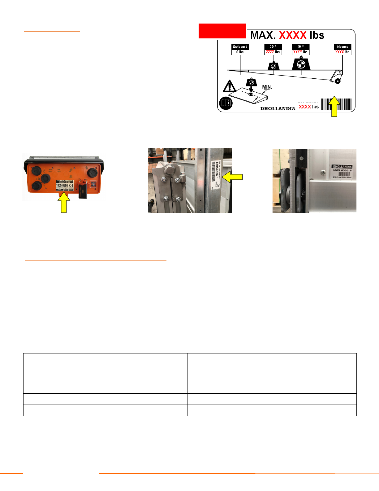
• Every HOLLAN IA liftgate is identified by and labelled with a
uniqu 8-digit s rial numb r (with or without a space
between the first and last 4 digits). Use this number for any
inquiry on a particular liftgate, or when ordering replacement
parts.
• In addition to the liftgate type and serial number, the various
serial number labels provide additional information, such as:
the maximum rated lift capacity and load chart, the bumper
certification number, the date of manufacture, etc...
• These labels are usually affixed to the vehicle body and
various liftgate components, and can be found in following
locations (the yellow arrows point to the serial numbers):
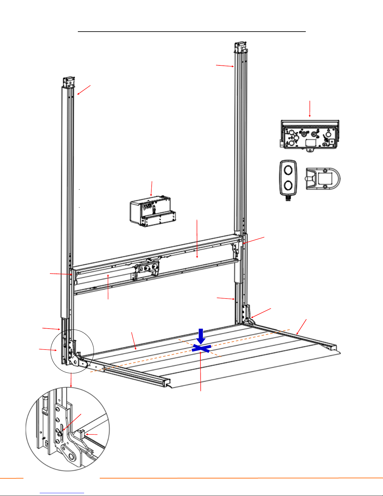
6. DESCRIPTION AND LIFTGATE TERMINOLOGY
• HOLLAN IA liftgates are developed and manufactured using state-of-the-art technology, high quality materials and components,
and highly skilled workmanship.
• The H-VO.07.K9, H-VO.15.K9 and H-VO.20.K9 comprise of a range of column liftgates, designed for a wide variety of trucks,
trailers and semi-trailers, and is available with lift capacities ranging from 1,000 to 4,400 lbs.
• In its travel position, the platform of the column liftgate is stowed vertically behind the vehicle body. Before use, the platform is
lowered approx. 7 “, then tilted open 90 degrees from the vertical travel position, to a horizontal work position.
• epending on liftgate model and options chosen, the opening and closing of the platform can be manual, or driven by 1 or 2
hydraulic tilt cylinders. See table below:
EXAMPLE
Affixed to the side of the vehicle body, or on the platform
On the lift frame On the platform
On the main external control box
Typ Lift capacity Manual closur Hydraulic closur 0-90°
OVH004
Hydraulic closur with adjustabl
platform pitch
OVH011
H-VO.07.K9 1,100 - 1,650 lbs standard not available not available
H-VO.15.K9 2,200 - 3,300 lbs standard optional optional
H-VO.20.K9 3,300 - 4,400 lbs standard optional optional
18050306
DH-VO.07

DHOLLANDIA 7
DH-VO.07.K9 / DH-VO.15.K9 ● MANUAL CLOSURE ● LIFTGATE TERMINOLOGY
See figure below for parts corresponding to numbers in this table
# D scription
1 Lift columns: set of 2 columns mounted in a fixed position against the vehicle body. These form the rails within which the lift
runners carrying the platform travel up and down.
2 Cylind r b am: horizontal beam mounted at the vehicle floor. This beam contains the lift cylinder; the drive system
consisting of chains and pulleys; and often also the hydraulic pump unit.
3 Lift cylind r(s): 1 or 2 hydraulic cylinder(s) used to LOWER / LIFT the lift runners, the platform and its load. K9 executions
have 1 lift cylinder, and offer a lifting height limited to approx. 70” (depending on vehicle width). K9+K2 executions have 2 lift
cylinders, and offer a much higher lifting height.
4 Hydraulic pump unit: contains the electric motor driving the hydraulic pump, the oil tank, and the control valves. The unit is
mounted separately on the vehicle chassis.
5 Platform: carries the load during lifting and lowering. Manufactured from steel or light-weight aluminium and with a non-slip
working surface. In standard execution, the platform is equipped with a fixed leading edge. Optional cart-stops in the platform
surface, or a retention ramp at the outboard platform edge, are available as an option.
6 Torsion bar(s): powerful spring device hidden inside the platform, assisting with the manual OPEN / CLOSE of the platform
(in case of manual closure)
7 Lift runn rs: set of 2 slides carrying the platform, travelling up and down in the lift columns. They are lifted and lowered by
the lift cylinder and the drive mechanism (chains and pulleys).
8 Stow lock: set of 2 lock plates mounted on left and right side at the inboard platform edge. To stow the platform in its travel
position, CLOSE the platform from the open work position to the vertical position. Then LIFT the vertical platform against the
underside of the cylinder beam until you hear the hydraulic system turn in over-pressure.
9 Platform lock: up and down sliding lock on the near-side lift runner with dual function:
1. Platform in vertical position: the lock holds the platform closed against the lift runners. Release the platform lock to open
the platform.
2. Platform in horizontal position: the lock blocks the platform in work position, and prevents the torsion bar(s) from tilting up
the platform. Release the platform lock to close the platform.
10 Main xt rnal control box: mounted in a fixed position at the side of the vehicle or under the body. It contains the electrical
switches to LOWER / LIFT the platform.
11 C nt r point of maximum load: point up to which the maximum rated capacity of the liftgate is valid. Beyond that point, the
maximum safe working load diminishes according to the applicable load charts found at Section 8 of this manual.

DHOLLANDIA 8
DH-VO.07.K9 / DH-VO.15.K9 ● MANUAL CLOSURE ● LIFTGATE TERMINOLOGY
1
1
2
3
4
5
6 7
7
8
8
8
9
10
11
8
8, 9

DHOLLANDIA 9
DH-VO.15.K9 ● HYDRAULIC CLOSURE REF. OVH004 ● LIFTGATE TERMINOLOGY
See figure below for parts corresponding to numbers in this table
# D scription
1 Lift columns: set of 2 columns mounted in a fixed position against the vehicle body. These form the rails within which the lift
runners carrying the platform travel up and down.
2 Cylind r b am: horizontal beam mounted at the vehicle floor. This beam contains the lift cylinder; the drive system
consisting of chains and pulleys; and often also the hydraulic pump unit.
3 Lift cylind r(s): 1 or 2 hydraulic cylinder(s) used to LOWER / LIFT the lift runners, the platform and its load. K9 executions
have 1 lift cylinder, and offer a lifting height limited to approx. 70” (depending on vehicle width). K9+K2 executions have 2 lift
cylinders, and offer a much higher lifting height.
4 Hydraulic pump unit: contains the electric motor driving the hydraulic pump, the oil tank, and the control valves. The unit is
mounted separately on the vehicle chassis.
5 Platform: carries the load during lifting and lowering. Manufactured from steel or light-weight aluminium and with a non-slip
working surface. In standard execution, the platform is equipped with a fixed leading edge. Optional cart-stops in the platform
surface, or a retention ramp at the outboard platform edge, are available as an option.
6 Torsion bar(s): powerful spring device hidden inside the platform, assisting with the manual OPEN / CLOSE of the platform
(in case of manual closure)
7 Lift runn rs: set of 2 slides carrying the platform, travelling up and down in the lift columns. They are lifted and lowered by
the lift cylinder and the drive mechanism (chains and pulleys).
8 Stow lock: set of 2 lock plates mounted on left and right side at the inboard platform edge. To stow the platform in its travel
position, CLOSE the platform from the open work position to the vertical position. Then LIFT the vertical platform against the
underside of the cylinder beam until you hear the hydraulic system turn in over-pressure.
9 Tilt cylind r: optional hydraulic cylinder used to OPEN / CLOSE the platform. The option OVH004 offers hydraulic instead
of manual OPEN / CLOSE, but does not offer adjustable platform orientation.
10 Main xt rnal control box: mounted in a fixed position at the side of the vehicle or under the body. It contains the electrical
switches to OPEN / LOWER / LIFT / CLOSE the platform.
11 C nt r point of maximum load: point up to which the maximum rated capacity of the liftgate is valid. Beyond that point, the
maximum safe working load diminishes according to the applicable load charts found at Section 8 of this manual.

DHOLLANDIA 10
9
DH-VO.15.K9 + K2 ● HYDRAULIC CLOSURE REF. OVH004 ● LIFTGATE TERMINOLOGY
1
1
2
3
4
5
6
7
7
8
8
8
9
10
11
8
8

DHOLLANDIA 11
DH-VO.20.K9 ● HYDRAULIC CLOSURE REF. OVH011 ● LIFTGATE TERMINOLOGY
See figure below for parts corresponding to numbers in this table
# D scription
1 Lift columns: set of 2 columns mounted in a fixed position against the vehicle body. These form the rails within which the lift
runners carrying the platform travel up and down.
2 Cylind r b am: horizontal beam mounted at the vehicle floor. This beam contains the lift cylinder; the drive system
consisting of chains and pulleys; and often also the hydraulic pump unit.
3 Lift cylind r: hydraulic cylinder used to LOWER / LIFT the lift runners, the platform and its load.
4 Hydraulic pump unit: contains the electric motor driving the hydraulic pump, the oil tank, and the control valves. The unit is
mounted separately on the vehicle chassis.
5 Platform / Foldabl platform (optional): carries the load during lifting and lowering. Manufactured from steel or light-weight
aluminium and with a non-slip working surface. In standard execution, the platform is equipped with a fixed leading edge.
Optional cart-stops in the platform surface, or a retention ramp at the outboard platform edge, are available as an option.
5a Platform main s ction: inboard section of the (optional) foldable platform. Manufactured from steel, with a non-slip working
surface.
5b Flip-ov r point: foldable outboard section of the (optional) foldable platform. Manufactured from steel or light-weight
aluminium, with a non-slip working surface.
6 Lift runn rs: set of 2 slides carrying the platform, travelling up and down in the lift columns. They are lifted and lowered by
the lift cylinder and the drive mechanism (chains and pulleys).
7 Stow lock: set of 2 lock plates mounted on left and right side at the inboard platform edge. To stow the platform in its travel
position, CLOSE the platform from the open work position to the vertical position. Then LIFT the vertical platform against the
underside of the cylinder beam until you hear the hydraulic system turn in over-pressure.
8 Tilt cylind rs: optional hydraulic cylinders (option OVH011) used to OPEN / CLOSE the platform, or to TILT OWN / TILT
UP the platform, and adjust its pitch to the slope of the ground.
9 Main xt rnal control box: mounted in a fixed position at the side of the vehicle or under the body. It contains the electrical
switches to OPEN / LOWER / LIFT / CLOSE the platform.
10 C nt r point of maximum load: point up to which the maximum rated capacity of the liftgate is valid. Beyond that point, the
maximum safe working load diminishes according to the applicable load charts found at Section 8 of this manual.

DHOLLANDIA 12
DH-VO.20.K9 ● HYDRAULIC CLOSURE REF. OVH011 ● LIFTGATE TERMINOLOGY
10
9
1
1
2
4
3
5
5a
5b
6
6
7
7
6
8
8
8
7

DHOLLANDIA 13
DH-VO.07.K9 / DH-VO.15.K9 ● LOAD RESTRAINTS ● LIFTGATE TERMINOLOGY
See figure below page for parts corresponding to numbers in this table
# D scription
1 Platform: carries the load during lifting and lowering. Manufactured from steel or light-weight aluminium and with a non-slip
working surface. In standard execution, the platform is equipped with a fixed leading edge. Optional cart-stops in the platform
surface, or a retention ramp at the outboard platform edge, are available as an option.
2 Cart-stops: usually 2 load restraint flaps mounted in or just in front of the fixed leading edge of the platform. epending on
options chosen, the cart-stops feature a manual or an automatic operation (see also §9.8 from page 49 onwards) and are
actuated by springs.
3 R ar or outboard r t ntion ramps : 1 full-width or 2 partial width load restraints ramps mounted at the outboard platform
edge. In travel position, the ramps lie folded back on the platform surface. When travelling up and down, the ramps can be
raised and blocked in vertical position to prevent rolling cargo on the platform from falling off. At the ground, the ramps can be
deployed as an access ramp to drive cargo on and off the platform. (See also §9.8 from page 49 onwards).
4 Sid r t ntion ramps : 2 load restraints ramps mounted at the side edges of the platform. In travel position, the ramps lie
folded back on the platform surface. When travelling up and down, the ramps can be raised and blocked in vertical position to
prevent rolling cargo on the platform from falling off. At the ground, the ramps can be deployed as an access ramp to drive
cargo on and off the platform. (See also §9.8 from page 49 onwards)
1
2
1
3
4
4

DHOLLANDIA 14
7. SAFETY INSTRUCTIONS FOR USING THE LIFTGATE
§7.1 - DO NOT us liftgat without ad quat saf ty and op rator training
• HOLLAN IA liftgates shall be exclusively used to load and unload the goods transported on the carrying vehicle, within the limits
of the applicable load chart, in compliance with the operator instructions and safety instructions in this manual.
• The operator should follow all other policies and procedures applicable to the job situation including health & safety regulations,
road and traffic regulations, as well as company procedures The operator should not use the liftgate if he/she cannot use it in
accordance with all applicable regulations and instructions.
• The operator shall be at least 18 years of age.
• Improper use of the liftgate will put the operator and other parties at great risk of serious bodily injury and death.
• To reduce the risk of serious bodily injury to the operator and any bystanders, the use of the liftgate is restricted to skilled
operators, who have been properly trained, and who know and understand the full contents of this manual.
• To reduce the risk of serious bodily injury or death, THE OPERATOR MUST COMPLY WITH ALL SAFETY INSTRUCTIONS
AN WARNING LABELS IN THIS SECTION AN THE ENTIRE MANUAL before and while operating the liftgate.
§7.2 - G n ral saf ty instructions
• To avoid serious bodily injury or death, the operator must use appropriate work clothes. NEVER wear loose-fitting clothes that
may be trapped in the moving parts of the liftgate. ALWAYS wear professional safety-toe shoes, protective gloves, and eye
protection. Use of hardhat is recommended.
• Slipping (and falling) can result in serious bodily injury and death. To prevent injury by slipping:
→ ALWAYS wear professional safety-toe shoes with a good non-slip sole.
→ O NOT use the liftgate if it is covered with snow, mud, dirt, debris, liquids or other substances.
→ O NOT run on the platform.
• Tripping (and falling) can result in serious bodily injury and death. To prevent injury by tripping:
→ O NOT use liftgate platform as a step. NEVER leave the liftgate unattended in partially deployed position.
→ Pay attention to protruding items on the platform surface at all times (ex. platform lights, cart-stops and
their levers, foreign objects, etc…).
→ O NOT run on the platform.
• Falling from the platform can result in serious bodily injury and death. To prevent injury by falling:
→ Make sure your footing is solid, and maintain 3 points of contact. See §7.4.1 from page 21 onwards.
→ Use safety rails where available. See §7.4.1 from page 21 onwards.
→ NEVER move the vehicle while a person is standing on the platform, or inside the vehicle body.
→ NEVER use the platform as an elevated working platform.
Must: Recommended:

DHOLLANDIA 15
• Prior to operating the liftgate, the vehicle must be safely parked on level and solid ground, the parking brake applied, and the
engine must be switched off. Lock open the rear doors and secure all other moving parts of the vehicle body. Failure to abide
by these instructions can result in serious bodily injury or death to the operator or bystanders.
• Ensure that the vehicle cannot tip-over when putting heavy weight on the platform. If the vehicle or the liftgate are equipped
with mechanical or hydraulic stabilizing legs, deploy these before opening the platform. Ensure that the stabilizing legs are
positioned on solid even ground. In case of soft terrain (sand, gravel,…), solid support blocks must be used under the
stabilizing legs. Failure to abide by these instructions can result in serious bodily injury or death to the operator or bystanders.
• To reduce the risk of serious bodily injury or death which may
result from other vehicles when parked, ALWAYS make sure
a safety distance of 16 ft. or 5 m. is kept between the back of
the truck and the following vehicle
• To reduce the risk of serious bodily injury or death, ALWAYS
make sure the platform is clearly visible to other persons
from all approach directions. HOLLAN IA recommends the
use of 4 warning cones, placed around the work area of the
platform . [See notice below].
• To reduce the risk of serious bodily injury or death, make
sure the working zone is sufficiently lighted.
NOTICE
HOLLAN IA offers optional platform mounted flashing lights and flags to make the platform more visible to other people. Please
visit www.dhollandia.com or contact the national HOLLAN IA distributor for more information. See page 4 for contact info.

DHOLLANDIA 16
• Prior to releasing the mechanical platform lock (if so equipped) and using the liftgate, check if the liftgate can be used safely.
Take precautions to ensure your own safety, and the safety of bystanders or other parties in traffic. Clear the working area of
any objects that could potentially impede movement of the liftgate. Failure to abide by these instructions can result in serious
bodily injury or death to the operator or bystanders.
• Inspect the liftgate prior to each use. If any unsafe condition exists or unusual noises or movements
are noticed, O NOT use the liftgate, attach the ‘WARNING. LIFTGATE OUT OF SERVICE. O
NOT ATTEMPT TO OPERATE’ decal to the main external control box or platform, and contact an
authorized HOLLAN IA service agent for repair. Please see ‘pre-trip inspection’ procedures under
§7.7 on page 29-30.
• When unloading from the vehicle body to the platform,
ALWAYS push the load out, to prevent the load from hitting
you. NEVER pull the load from the vehicle onto the platform.
Pulling the load from the vehicle can result in a fall from the
platform causing serious injury or death.
• Read and comply with all warning decals, pictograms and instructions affixed to the liftgate. Failure to abide by warnings and
instructions may result in serious bodily injury or death.
• The liftgate must not be used if the operator is intoxicated, impaired or distracted in any way. NEVER use a phone or mobile
device when operating the liftgate.
• The liftgate shall be used by means of original control units only. Operating the liftgate with unauthorized control units will
increase risk of serious bodily injury or death to the operator or any bystanders.
• Limit the operation of the liftgate to one single operator. Operation of the liftgate by more than one operator at a time may
cause confusion and increase the risk of serious bodily injury or death.
• To prevent people from being hit by the platform, by objects falling off the platform or being caught in pinch points or being
pinched by the moving parts of the liftgate:
→ Keep visual control over the entire working area of the liftgate and its platform at all times, including the area
IRECTLY BEHIN and UN ER the platform.
→ O NOT allow any other person, to stand in the proximity of the liftgate and its platform. ENSURE AT ALL
TIMES THAT NOBO Y STAN S UN ER OR WITHIN REACH OF THE MOVING PLATFORM.

DHOLLANDIA 17
• If pushed out too far, the load can fall off the platform, and cause serious bodily injury or death to other people. eploy the cart-
stops or retention ramp before pushing out the load. If not available, push the load slowly while checking the outboard platform
edges.
• The load must ALWAYS be secured when raising or lowering
on the liftgate, to prevent it from shifting position and rolling
off the platform edges. Failure to properly secure the load
will increase the risk of serious bodily injury or death to the
operator or any bystanders.
• When using a pallet jack, lower and rest the pallet or load
upon the platform surface before operating the liftgate.
• For loads on wheels, engage wheel brakes of carts, trolleys
and machinery (if available) before operating the liftgate.
• For loads that could slip, the use of original HOLLAN IA cart-stops, retention ramp(s) or an appropriate alternative
securement device (ex. ratchet straps) is required. The load must not be able to move during movement of the platform. See
§9.8 from page 49 onwards for correct use of original HOLLAN IA cart stops and retention ramp(s).
• NEVER leave the liftgate unattended in open position. Before leaving the vehicle unattended, close the doors of the vehicle,
stow the platform in its travel position and switch OFF the main battery disconnect switch in the external control box (if so
equipped), or the cab switch. Leaving the liftgate in open position unattended can result in serious bodily injury or death to
unaware bystanders. See section 9 for instructions on properly stowing platform into its travel position.
• NEVER move the vehicle with the liftgate in the open position. ALWAYS close and secure the doors of the vehicle, stow the
liftgate in its travel position and switch OFF the main battery disconnect switch in the external control box (if so equipped), or
the cab switch, before moving the vehicle. If so equipped, close the mechanical platform lock after stowing the platform in its
travel position. Failure to properly stow the liftgate in its travel position prior to moving the vehicle may result in serious bodily
injury or death.
• Use of the liftgate near vehicular traffic may result in serious bodily injury or death from being struck by another vehicle. When
operating the liftgate on or near a street or parking lot, be sure to stay clear of vehicular traffic. ALWAYS be sure to clearly
identify to other drivers that the liftgate is in use. hollandia recommends use of warning cones to clearly identify to drivers that
the liftgate is being operated. When the liftgate is operated near vehicular traffic, wear working clothes in high-visibility colors
and a retro-reflective safety vest.
• O NOT raise the liftgate with the rear doors partially open. oing so may damage the doors or the liftgate platform and may
also result in serious bodily injury or death to the operator or any bystanders.
• Above all, USE GOO COMMON SENSE when operating the liftgate. O NOT operate the liftgate until the contents of this
manual have been read and fully understood. Improper use of the liftgate increases the risk of serious bodily injury or death to
the operator and any bystanders.

DHOLLANDIA 18
§7.3 - Dang r zon s, risk of crush and sh ar injury
• There are 4 main danger zones on and around the platform, that can be hazardous to the operator and any other persons nearby:
Correct operator position
anger zone
1. ALWAYS stay clear of the
range of motion of the platform
❷
2. Beware of crushing zone between
lowering platform and ground
Impact by the platform or the moving parts of the liftgate will result in serious bodily injury or death. To
prevent people from being hit by the platform, by objects falling off the platform or being caught in pinch
points or being pinched by the moving parts of the liftgate:
→ Keep visual control over the entire working area of the liftgate at all times, including the area directly
behind and under the platform;
→ O NOT allow any other person to stand near the liftgate and its platform. Ensure at all times that nobody
stands under, or within reach of the moving platform and its load.
❸
❶
❷
❸
3. Beware of the crushing zone between rising
platform and vehicle floor
❶

DHOLLANDIA 19
4. Beware of the crushing zone between closing
platform and rear frame of vehicle body
❹
❹
4 [continued]. Most column lifts are equipped with a
device that shut closes the platform tight against the lift
columns, after it was tilted in the vertical position and
while it is lifted in its travel position.
Therefore, the operator MUST stand on the side of the
platform and keep head, limbs and upper body clear of
hazardous space between the platform and the lift
columns, while stowing the platform in its travel position.
4 [continued]. In case of platforms equipped with manual closure and automatically folding safety rails (sides only), or gas-bottle execution (sides +
rear), make sure you use the grab handle on the safety rail to open and close the platform.
• Opening and closing of the platform by holding
the steel members of automatically folding
safety rails can crush the operator’s hands
between the moving elements of the safety rail.
• To avoid bodily injury, always use the grab
handle to manually open or close the platform
and its safety rails, and beware of pinch points
at all times.

DHOLLANDIA 20
The operator or other persons approaching too close to these danger zones risk serious bodily injury or death
by pinching, crushing or shearing of limbs, upper body or head. To prevent these hazards:
→ ALWAYS stand clear of the range of motion of the platform and moving parts of the liftgate;
→ Keep hands, feet and upper body clear of pinch points and moving parts of the liftgate;
→ O NOT allow any other person to stand near the liftgate and its platform.
This manual suits for next models
2
Table of contents
Other Dhollandia Lifting Column manuals
Popular Lifting Column manuals by other brands

LINCOS
LINCOS STD-3550 manual

progressive automations
progressive automations FLT-04 Assembly instructions

Suspa
Suspa ELS3 installation instructions

Titan Lifts
Titan Lifts HD2P-11000ACX Installation, operation & maintenance manual

MAHA
MAHA RGB Original operating instructions

MAHA
MAHA RGE Original operating instructions