Ceiling Fan Wall-Mounted Control
Installation Instruction
IMPORTANT POINTS TO REMEMBER:
1. Please read this instruction and save it for further use.
2. Please note that all fixed wiring appliances should be
installed by a qualified electrician.
3. To avoid possible electrical shock, be sure electricity is
turned off at the main fuse box or circuit panel before wiring.
4. Do not mount wall control near heat producing equipment.
5. Use of this control with some ceiling fans could result in fire,
shock and serious personal injury. Use this ceiling fan
wall-mounted control only with ceiling fan capacitor speed
controlled only.
6. Make certain no bare wires are exposed outside the
connectors.
7. This unit is to be used for the control of ceiling fans at
AC250V 50Hz power supply only.
8. Controller must be installed by a licensed electrician
INSTALLATION INTRUCTIONS:
1. Disconnect the power and remove the existing wall plate
and switch.
2. If your ceiling fan is equipped with a pull chain switch,
make sure to set the speed control at the highest speed
before installing the wall control.
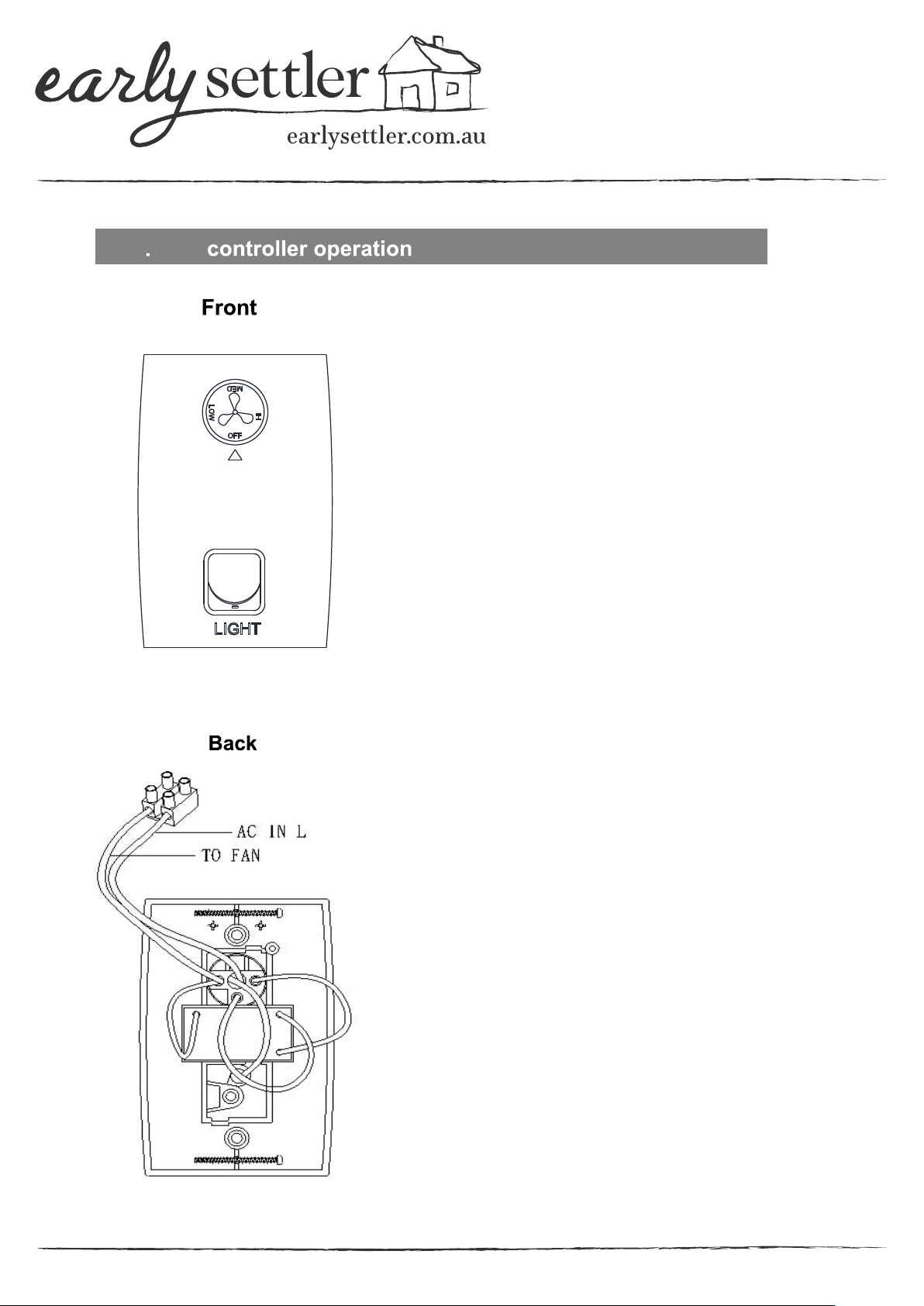
3. Set the knob on the wall-mounted control in the off position.
4. Make wire connections and secure with 2pcs wire connectors.
5. Secure the wall-mounted control to the outlet box with two
screws provided. Then, the face plate clicks on the wall control.