East Tester ET1080A User manual

ET1080A/1080B/1080C/1080D/1080E
Handheld LCR Meter
User Manual
Hangzhou Zhongchuang Electronics Co., Ltd.

Contents
1. Safety.....................................................................................................................................1
2. Instruction on safety............................................................................................................ 1
3. Introduction........................................................................................................................... 1
4. Overview of front panel.......................................................................................................2
4.1 Front panel..................................................................................................................2
4.2 User’s interface..........................................................................................................3
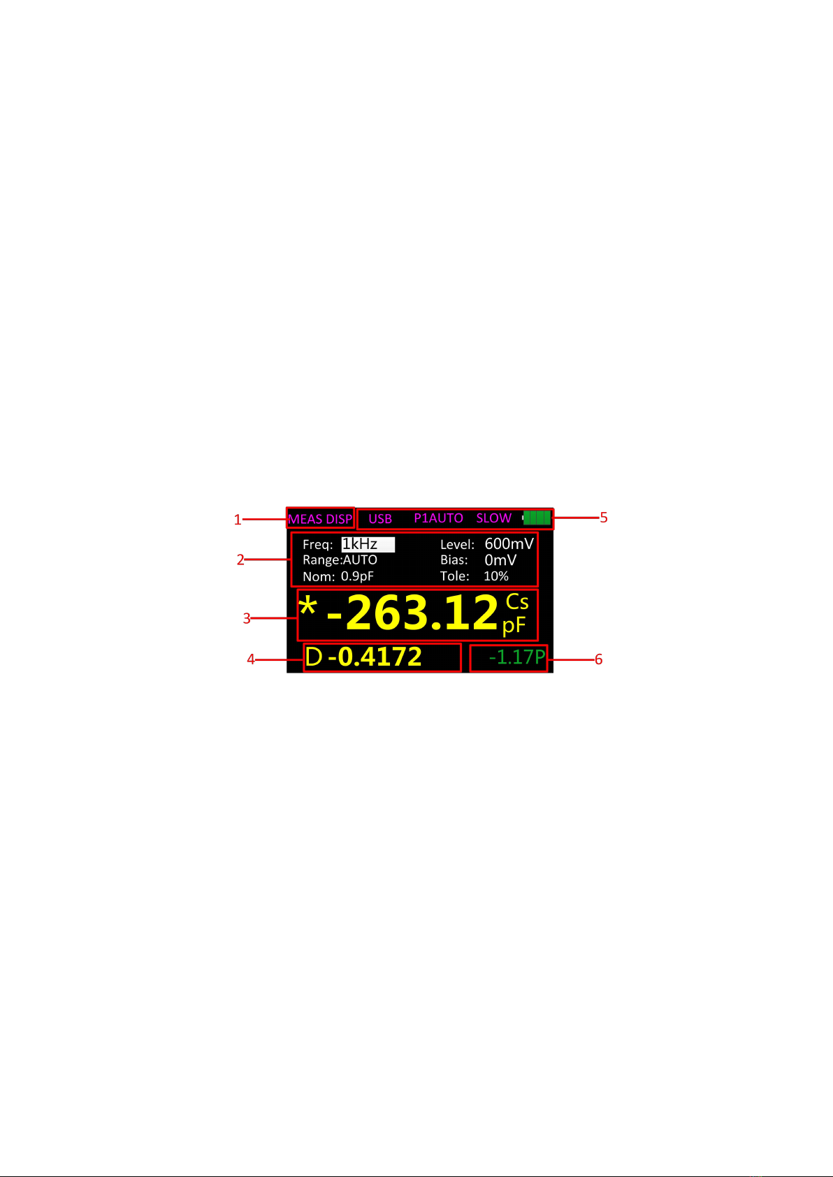
4.2.1. Measurement interface................................................................................ 3
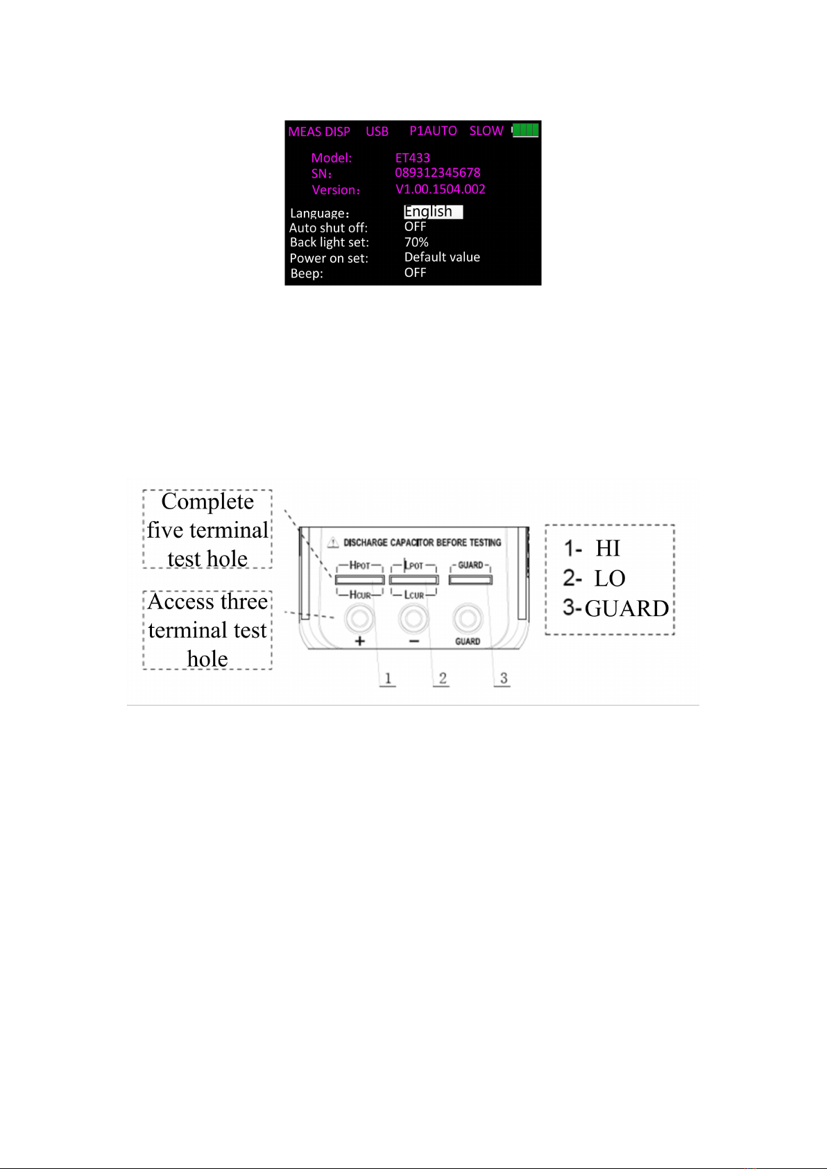
4.2.2 System settings interface............................................................................. 4
4.3 Test port.......................................................................................................................4
5. Operation instruction........................................................................................................... 4
5.1 Startup and shutdown...............................................................................................4
5.2 Selection of parameter............................................................................................. 5
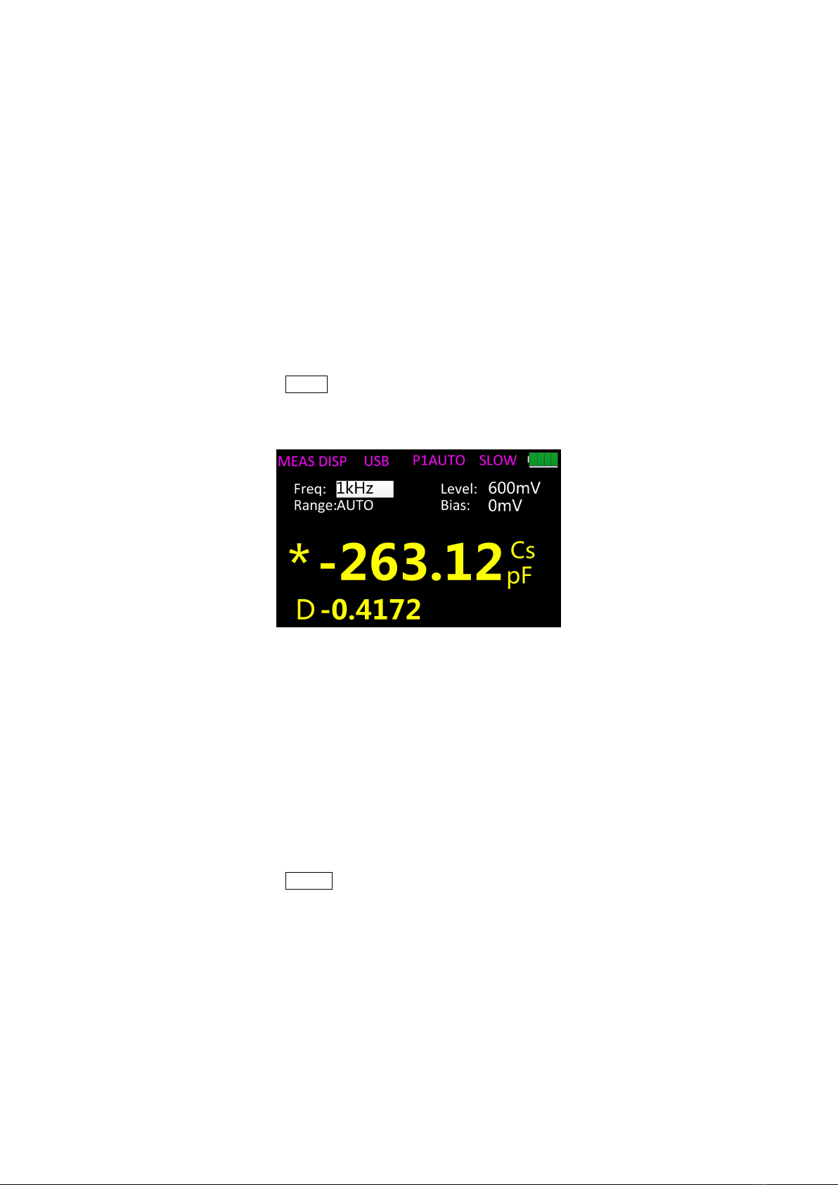
5.2.1 Selection of frequency...................................................................................5
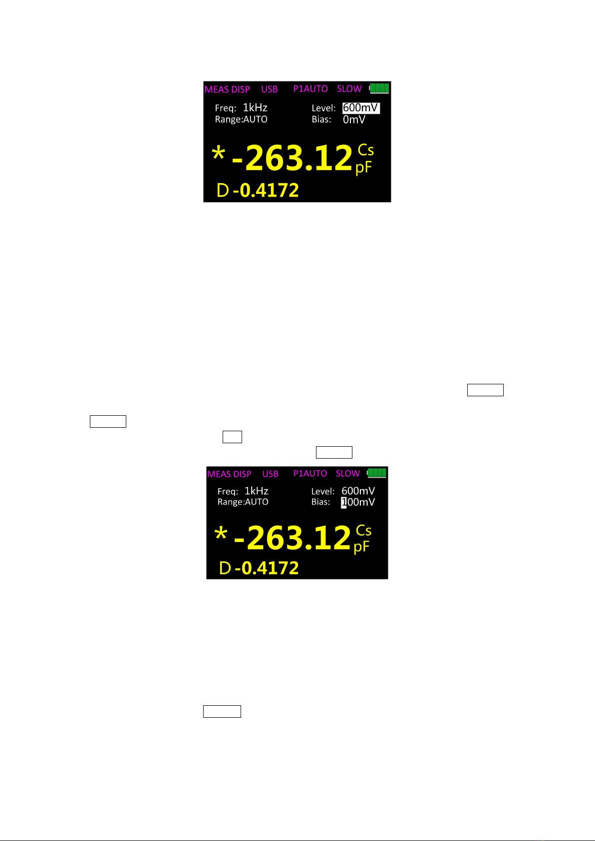
5.2.2 Selection of level............................................................................................ 5
5.2.3 Selection of internal bias...............................................................................6
5.2.4 Selection of range.......................................................................................... 6
5.2.5 Selection of measurement speed................................................................7
5.2.6 Selection of L/C/R/Z main parameters....................................................... 7
5.2.7 Selection of X/D/Q/θ/ESR secondary parameters................................... 7
5.2.8 Selection of tolerance....................................................................................7
5.2.9 Selection of nominal...................................................................................... 8
5.2.10. Selection of equivalent...............................................................................8
5.3. DCR mode.................................................................................................................8
5.4. Electrolytic capacitance mode................................................................................8
5.5. Relative mode........................................................................................................... 9
5.6. Reading hold mode (HOLD)...................................................................................9
5.7 Data recording function (maximum, minimum, average)....................................9
5.8 Comparator function............................................................................................... 10
5.9 Correction function..................................................................................................10
6. Rapid application guide.................................................................................................... 10
6.1 Resistance measurement...................................................................................... 11
6.2 Capacitance measurement....................................................................................12
6.3 Inductance measurement...................................................................................... 13
6.4 Impedance measurement...................................................................................... 14
7. Telecommunication............................................................................................................14
8. Instrument parameters......................................................................................................17
8.1 General parameters................................................................................................17
8.2 Measurement accuracy..........................................................................................17
8.3 Accuracy indicator................................................................................................... 21
8.3.1. Accuracy indicator 1(ET433).....................................................................21
8.3.2 Accuracy indicator 2(ET432/ET431).........................................................22
8.3.3 Accuracy indicator 3(ET430 and ET430B).............................................. 27
8.3.4 Accuracy indicator 4(DCR)..........................................................................31
9. Maintenance....................................................................................................................... 31
9.1. Overhaul.................................................................................................................. 31
9.2 Clean......................................................................................................................... 31

User’s Guide of ET43 Series Handheld Bridge
Hangzhou Zhongchuang Electronics Co., Ltd.
1
1. Safety
These security measures are applicable to the operation and maintenance personnel who
should pay attention to them during service and maintenance.
Do not use in explosive environments
Avoid using it in dusty environment, in direct sunlight, in environment with high humidity
or strong electromagnetic radiation or other harsh environments.
Non-professional maintenance personnel should not open
the back cover
Maintenance, replacement of components or adjustment of the instrument should be done
by professional maintenance personnel. Please contact the dealer and the service
department of Hangzhou Zhongchuang Electronics Co., Ltd.
Do not arbitrarily break down or modify the instrument
Partial replacement or unauthorized modification may prevent the instrument from
recovering its performance
Security warning
One should abide by the relevant terms in the manual regarding safety or injury to human
body or damages to the product, as well as operation or environment which may result in
test failure.
2. Instruction on safety
To allow safe use of equipment, follow these guidelines:
The instrument is suitable for indoor use and an altitude of less than 2,000 meters.
In case of short-term outdoor use, prevent it from direct sunlight, water,
electromagnetic radiation, dust, etc.
Before the use, please read and understand the warning and safety information
mentioned in this manual.
Use the instrument according to the function specified in the manual.
If the component needs measurement, make sure the circuit is turned off and all
capacitors in the circuit are discharged before the measurement.
Before the measurement, components such as capacitors shall be discharged.
The lithium battery of 5V and 2600mAh, or mini_USB is used to provide power for
the instrument.Can be charged with mini_USB.
Safety Symbols
Security warning to remind the user to following the instruction in the manual
Environmental conditions
Working environment: 0 ℃~ 40 ℃;
Humidity: 15% to 85% R.H;

User’s Guide of ET43 Series Handheld Bridge
Hangzhou Zhongchuang Electronics Co., Ltd.
1
Storage temperature: 0 ℃~ 40 ℃;
Pollution degree: 2;
3. Introduction
ET1080 Series handheld LCR is a portable hand-held measuring instrument for
measuring the parameters of inductors, capacitors, resistors and other components. It is
small with a 5V lithium battery, suitable for table-type application. It is also portable and
mobile.
ET1080 Series provides a resolution of four and a half digits for main parameters and
a resolution of 0.0001 for secondary parameter. Its highest measurement frequency is
100kHz, and can measure the level of 1Vrms, 0.6Vrms, 0.3Vrms, and 0.1Vrms(ET433 is
0~1V adjustable ). Its automatic range can display the results in the fast, medium, or slow
mode. It can automatically select the appropriate measurement parameters according to
the characteristics of the component. Its measurement accuracy can reach 0.2%. It
combines the convenience of a handheld instrument and good performance of a
table-type one.
The operation is simple, and users can see the test frequency, parameters, and
speed by pressing the corresponding key; it also has the recording mode to take readings;
the convenient operation of open and short circuit correction function helps improve the
measurement accuracy. The buzzer, automatic power off and languages can be set on the
configuration menu
The standard instrument is equipped with remote communication function. The
remote control and data acquisition are achieved by connecting it to the PC through
Mini-USB cable.
Packing list
The packing box of ET1080 Series is equipped according to the following list:
a handheld LCR (lithium battery installed)
a guidance manual
CD
a Mini-USB communication cable
an AC power adapter
a pair of red / black rubber plugs –alligator clip test line
a short-circuit bar
a pair of 4-terminal Kelvin test clip (optional for ET430/430B, and other models
standard)
Please check according to the packing list after the box is opened, if any component is
missing, please immediately contact the company or the related dealer.

Hangzhou Zhongchuang Electronics Co., Ltd.
2
4. Overview of front panel
Figure 1 Front panel (with ET431 as an example)
4.1 Front panel
The front panel is described below, taking ET1080C as an example. See figure 1 (Note:
the long press in the manual indicates to press and hold the key for more than 2 seconds.
There is the short press and long press for the multifunction key, but only short press for
other keys)
1 Display 2.8” TFT LCD screen, which displays all functions of the instrument.
2 Data holding recording multifunctional key short press to turn on or off the data
holding function; long press to turn on or off the data recording function.
3 Power key long press it to turn on or off the instrument;
4 Main parameter shortcut key to switch the main parameters quickly.
5 Relative and correction multifunctional key short press to turn on or off the relative
function, long press to turn on the correction function.
6 Secondary parameter shortcut key to quickly switch the secondary parameters.
7 Frequency and DCR mode multifunctional key short press to fast switch the
frequency of fixed points; long press to enter the DCR mode.
8 Level shortcut key to quickly switch the fixed-point level.
9 Bias voltage and electrolytic capacitance mode multifunctional key short press
to enter the electrolytic capacitance mode; long press to quickly select bias voltage.
10 Equivalent shortcut key to quickly switch equivalents.
11 Interface switch key to quickly switch between "measurement display" and "System
Settings".
12 Comparator switch and tolerance limits shortcut multifunctional key short
press to quickly switch deviation tolerance limit; long press to turn on or off the
comparator.

Hangzhou Zhongchuang Electronics Co., Ltd.
3
13 Measuring speed shortcut key to quickly switch the required measurement speed.
14 Range shortcut key to quickly switch the required range.
15 Arrow keys left and right arrow keys to control the movement of the cursor; up and
down arrow keys to select the parameter.
16 Enter key to confirm the selection of a certain parameter or function.
17 5-terminal test notch
18 3-terminal test jack
Note: please see the label on the adapter for its input parameters; use the
supplied adapter, or purchase the specified power adapter from our company.
The use of other adapters may cause unnecessary damage.
Reminder: after the external power supply is normal, the internal battery power
supply circuit will be automatically cut off and charge the battery, ET43 Series
has an independent charging management controller—even when the
instrument is turned off, the charging control still works normally.
4.2 User’s interface
4.2.1. Measurement interface
Figure 2 Measurement interface
1 Page title used to identify the page displayed.
2 Measurement parameter settings
3 Main parameter display "*" indicates the data holding state.
4 Secondary parameter display
5 Status Bar "USB": USB connection, displayed when it is connected to the PC and hidden
at any other time;
"Main Parameter Auto": the main parameters are displayed in automatic
mode and hidden at any other time;
"Slow": measurement speed display;
The icon of the battery indicates the remaining power to
remind the user of charging the instrument.
6 Comparator display shows the deviation percentage of the value of the tested
component to the nominal value, the green and P represent that it is within
the set tolerance, and red and F indicate that it exceeds the set tolerance.
The bar is closed when the comparator is turned off.

Hangzhou Zhongchuang Electronics Co., Ltd.
4
4.2.2 System settings interface
Figure 3 system settings interface
On the system settings interface users can view the product model, serial number
and version number. The language, automatic power-off, brightness, power-on, and
buzzer can be set.
4.3 Test port
ET1080 Series uses the 3- and 5-terminal test ports at the same time, which is to
combine convenience and high accuracy for the test. See figure 4 for the test terminal.
Figure 4 Test port
The three-terminal test port of the instrument uses the standard rubber jack; therefore
the inexpensive rubber plug - alligator clip can be used as the test line. It is very
convenient to apply the extended test, but it has the drawback of low testing accuracy.
To improve the accuracy of the test line when using the extension line, ET43 Series is
also equipped with the five-terminal test notch for dedicated test fixture. It renders
possible the complete four-terminal measurement of the extension line, so as to ensure
the high testing accuracy.
5. Operation instruction
5.1 Startup and shutdown
Long press the power key to start the instrument and the measurement interface is
shown (default); press and hold the key (for more than 2 seconds) to turn off the

Hangzhou Zhongchuang Electronics Co., Ltd.
5
instrument.
5.2 Selection of parameter
5.2.1 Selection of frequency
ET1080 Series handheld LCR applies AC test signal to the DUT for measurement.
Frequency is one of the main parameters of the AC source. Due to the presence of the
non-ideal and distributed parameters of elements, and the impact of the distributed
parameters between the test end, the same element may have different results with
different test frequencies. Therefore, before the measurement the appropriate frequency
should be selected.
There are two ways to change the test frequency:
Method One: press FREQ to switch between different frequencies.
Method Two: Press the right and left arrow keys to select frequency on the interface
as shown in figure 5, and press the up and down arrow keys to switch frequencies.
Figure 5
The following frequencies can be selected for different models:
ET1080 A/ET1080 C:100Hz、120Hz、1kHz、10kHz、
ET1080 C/ET1080 D:100Hz、120Hz、1kHz、10kHz、40kHz、100kHz;
ET1080 E:100Hz-100KHz,Continuously adjustable,a step of 1 Hz。
5.2.2 Selection of level
This Series handheld LCR applies AC test signal to the DUT for measurement. Both
the frequency and signal level can be changed.
There are two ways to change the test signal level:
Method One: press LEVEL to switch between different test signals.
Method Two: Press the right and left arrow keys to select level on the interface as
shown in figure 6, and press the up and down arrow keys to switch levels.

Hangzhou Zhongchuang Electronics Co., Ltd.
6
Figure 6
The following levels can be selected for different models:
ET1080C/ET1080D:1Vrms、0.6Vrms、0.3Vrms、0.1Vrms;
ET1080B: 0.6Vrms、0.3Vrms;
ET1080 A: 0.6Vrms;
ET1080E: 0-1V adjustable.
5.2.3 Selection of internal bias
ET1080Series offers internal bias 0-500mV, the DC bias voltage with stepping of 1mV
(ET1080B/ET1080A has no such function). When the test function is DCR, the bias is
800mV.
There are two ways to change the bias voltage:
Method One: press the right and left arrow keys to set the bias, and press ENTER,
press the up and down arrow keys to select the bias as shown in figure 7, and press
ENTER to confirm.
Method Two: long press-|(- to select the bias, press the up and down arrow keys to
select the required value of bias, and then press ENTER to confirm.
Figure 7
5.2.4 Selection of range
There are two ways to change the range:
Method One: turn on the instrument and the measurement display is shown, press
the left and right arrow keys to move the cursor to the range, and the up and down arrow
keys to switch the range (AUTO, 100Ω, 1kΩ, 10kΩ, 100kΩ).
Method Two: Press RANGE to switch directly to the next range, move the cursor to
the range at the same time.

Hangzhou Zhongchuang Electronics Co., Ltd.
7
5.2.5 Selection of measurement speed
Turn on the instrument and the measurement display is shown, press SPEED to
switch to the next measurement speed (fast, medium, slow). Above the status bar the
corresponding measurement speed is displayed. Fast (4 times / s), the speed (2 times / s),
Slow (1 time / s).
5.2.6 Selection of L/C/R/Z main parameters
Select the type of measurement parameter, and first select the main parameter.
Press AUTO/R/C/L/Z to switch between the following main parameters in sequence:
R (resistance), C (capacitance), L (inductance), Z (impedance) and AUTO (automatic).
When AUTO is selected for the main parameter, "Automatic Main Parameter" is displayed
above the status bar.
5.2.7 Selection of X/D/Q/θ/ESR secondary parameters
If necessary, press the secondary parameter key to select secondary parameter.
Press X/D/Q/θ/ESR to select the following secondary parameters:
D (loss), Q (quality factor), θ (phase angle), ESR (equivalent series resistance), X
(reactance).
5.2.8 Selection of tolerance
ET1080Ahas no such function.
There are two ways to set the tolerance:
Method One: 1. Turn on the instrument and the measurement display is shown, and
long press TOL% to open the comparator switch, at this moment the hidden
"tolerance," "nominal" and deviation percentage are displayed, as shown in
Figure 8;
Figure 8
2. Short press TOL% to switch to the next tolerance (1%, 5%, 10%, 20%).
Method Two: 1. The same as Method One;
2. Use the left and right arrow keys to move the cursor at the tolerance,
and then use the up and down arrow keys to switch to the last or next
tolerance.
Method Three: 1. The same as Method One;
2. Use the left and right arrow keys to move the cursor at the tolerance,

Hangzhou Zhongchuang Electronics Co., Ltd.
8
short press ENTER to enter the interface for custom tolerance (1% to 50%,
resolution ratio of 1%). Refer to the custom settings of frequency for the
setting method.
5.2.9 Selection of nominal
The method of setting the nominal is as follows:
1. Turn on the instrument and the measurement display is shown, the element with
required nominal should be placed on the test clip of the instrument.
2. Press TOL% to turn on the comparator, and the nominal value is the value of the
measured element with one digit after the decimal point, but it cannot be less than the
minimum unit (for example, if the measured element is 1.0694kΩ , then the nominal is 1kΩ;
for example, if the measured element is 330.92Ω, then the nominal is 330Ω).
3. If the nominal value is not the required one, use the left and right arrow keys to
move the cursor to the nominal, press ENTER to enter the interface for changing the
nominal value.
5.2.10. Selection of equivalent
Due to the non-ideal and distributed parameters of elements, the actual elements
tend to be equivalent with the combination of ideal elements. LCR tester generally uses
two simple equivalent models—series and parallel. Selecting the proper equivalent model
will lead to better measurement results. In general, low-impedance elements (such as that
below 100Ω) should use the series equivalent model; a high impedance element (such as
that above 10kΩ) should use the parallel equivalent model; the equivalent model affects
less the measurement result of the one in between the two above models. Press
AUTO/SER/PAL to switch to the next equivalent (SER, PAL).
5.3. DCR mode
ET1080 Series has the DCR mode except for ET1080B/ET1080A. Long press FREQ
to enter the DCR mode, as shown in figure 9.
100.00
-------
DCR
800mV
0mV
Ω
--- ---
Bias:
Level:Freq:
Range:AUTO
0Hz
MEAS DISP USB SLOW
Figure 9
5.4. Electrolytic capacitance mode
ET1080 Series has the electrolytic capacitance mode except for ET1080A. Long

Hangzhou Zhongchuang Electronics Co., Ltd.
9
press -|(- to enter the electrolytic capacitance mode, as shown in figure 10.
Figure 10
5.5. Relative mode
Short press ▲NULL to turn on the relative function and the current value is used as
reference. The reference value and relative value will be shown respectively on the
secondary and main display.
5.6. Reading hold mode (HOLD)
The data hold function is used to freeze the displayed data. The measurement is still
in progress, but the data on the LCD is not updated as the measurements proceed.
Turn on reading hold:
To turn on the reading hold function, press the HOLD key, and "*" will be shown on the
LCD to indicate that the data hold function is activated. And measurement results for the
main and secondary parameters are those displayed before pressing the HOLD key.
Turn off reading hold:
To turn off the reading hold function, press again the HOLD key, and "*" disappears
from the LCD; the instrument returns to normal measurement mode.
5.7 Data recording function (maximum, minimum,
average)
If the measurement data of the DUT see poor stability and fluctuate within a certain
range, use the data recording mode to acquire the readings. In the data recording mode,
the maximum, minimum and average can be dynamically obtained within a certain range.
Turn on the recording function:
Long press HOLD to turn on the data recording function, and the recorded value is
shown on the secondary display, and at this moment the HOLD function is not available,
short press HOLD to select the display of the maximum, minimum, or average.
Turn off the recording function:
Long press HOLD to turn off the data recording function.
Reminder: After changing the type of the measurement parameter, it
will automatically exit from the data recording function.

Hangzhou Zhongchuang Electronics Co., Ltd.
10
5.8 Comparator function
See 5.2.8 Selection of tolerance and 5.2.9 Selection of nominal value.
5.9 Correction function
The correction function applies to the open and short circuit. By correcting it can
effectively reduce the error of distributed parameters caused by the test line. The short
circuit correction can reduce the impact of the contact resistance and lead resistance on
the measurement of low impedance element; and the open circuit correction can reduce
the impact of the distributed capacitance and resistance between the two ends of the test
line on the measurement of high impedance element.
The method of correction is shown as follows:
1. Before entering the correction function, please ensure that the test terminals are
open- or short-circuited. Press ▲NULL to enter the correction interface, then the
instrument automatically identify whether it is open or short circuit as shown in Figure
11;
MEAS DISP
Bias: 0mV
Level: 600mVFreq:
Range:AUTO
USB SLOW
1kHz
CORR
Figure 11
2. Short press ▲NULL for open (OPEN) or short (SHORT) circuit correction and the
interface is shown as in Figure 12. If the correction is successful, the secondary
display shows "SUCESS"; or it shows "FAILED".
Note: Do not change the state of the test terminals during the correction.
3. After the correction ends, short press ▲NULL to return to the measurement
display.
Figure 12
6. Rapid application guide
Warning:

Hangzhou Zhongchuang Electronics Co., Ltd.
11
Do not measure the charged capacitor, or it may cause damage to the
instrument.
In case of measurement of on-board devices, make sure the power is
turned off. The active circuit cannot be measured directly.
When used in the dusty environment, the instrument is easy to gather
dirt, so it should be cleaned periodically to protect the test port to
prevent the dust from entering the instrument. The accumulation of
dust will be conductive and affect the use of the instrument.
Do not place the instrument directly in the environments with
explosives, direct sunlight and excessive heat.
Reminder: To achieve the proper measurement accuracy, refer to the
"correction function" section for open and short circuit correction before
the measurement. The test fixture can be rubber plug - alligator clip (see
figure 13), Kelvin test fixture (figure 14), or the component can be directly
inserted into the position 17 in figure 1 (notch). The rubber plug -
alligator clips are mainly used in the following examples.
Figure 13 Figure 14
6.1 Resistance measurement
See figure 15 for the connection test.
Figure 15
1. Long press the power key to start the instrument;
2. Press the AUTO/R/C/L/Z key until Rs is displayed on the interface which means to
select resistance measurement, shown in figure 16;

Hangzhou Zhongchuang Electronics Co., Ltd.
12
Figure 16
3. Insert the resistor into the test notch, or choose the appropriate test accessories (rubber
plug - alligator clip, Kelvin test fixture, etc.) and connect it with the measured resistance;
4. Press the FREQ key to select the desired test frequency, press LEVEL to select the
desired level;
5. To select another secondary parameter, press X/D/Q/θ/ESR
6. Read the measurement results from the screen.
Reminder: the AC signal is used by the instrument to measure the resistance, so the
test result reflects the AC resistance characteristics of the instrument instead of its DC
resistance.
6.2 Capacitance measurement
Warning: Make sure that the capacitor has been fully discharged before measuring.
See figure 17 for the connection test.
Figure 17
1. Long press the power key to start the instrument;
2. Press the AUTO/R/C/L/Z key until Cs is displayed on the interface which means to
select capacitance measurement, shown in figure 18;

Hangzhou Zhongchuang Electronics Co., Ltd.
13
-|(-
pF
MEAS DISP
-263.12
-0.4172
Bias: 0mV
Level: 600mVFreq: 1kHz
Range:AUTO
D
USB SLOW
*
1kHz
Cs
pF
Figure 18
3. Insert the capacitor into the test notch, or choose the appropriate test accessories
(rubber plug - alligator clip, Kelvin test fixture, etc.) and connect it with the measured
capacitor;
4. Press the FREQ key to select the desired test frequency, press LEVEL to select the
desired level;
5. To select another secondary parameter, press X/D/Q/θ/ESR
6. Read the measurement results from the screen.
Note: the capacitor or capacitive device must be fully discharged
before the test; the capacitor with large capacity may need longer time to
discharge. If the capacitive device not fully discharged is connected, it
can damage the components inside the instrument.
6.3 Inductance measurement
See figure 19 for the connection test.
Figure 19
1. Long press the power key to start the instrument;
2. Press the AUTO/R/C/L/Z key until Ls is displayed on the interface which means to
select inductance measurement, shown in figure 20;

Hangzhou Zhongchuang Electronics Co., Ltd.
14
Figure 20
3. Insert the inductor into the test notch, or choose the appropriate test accessories
(rubber plug - alligator clip, Kelvin test fixture, etc.) and connect it with the measured
inductor;
4. Press the FREQ key to select the desired test frequency, press LEVEL to select the
desired level;
5. To select another secondary parameter, press X/D/Q/θ/ESR
6. Read the measurement results from the screen.
6.4 Impedance measurement
1. Long press the power key to start the instrument;
2. Press the AUTO/R/C/L/Z key until Zs is displayed on the interface which means to
select impedance measurement, shown in figure 21;
Figure 21
3. Insert the impeder into the test notch, or choose the appropriate test accessories
(rubber plug - alligator clip, Kelvin test fixture, etc.) and connect it with the measured
impeder;
4. Press the FREQ key to select the desired test frequency, press LEVEL to select the
desired level;
5. To select another secondary parameter, press X/D/Q/θ/ESR
6. Read the measurement results from the screen.
7. Telecommunication
The instrument can be connected to PC through the Mini-USB interface. After
installing the driver on the PC, the ET1080 Series handheld LCR can be controlled from or
the test results acquired by the PC through the virtual serial port.

Hangzhou Zhongchuang Electronics Co., Ltd.
15
Connect the instrument to the PC:
1. Locate the USB driver software in the CD.
2. Use the Mini-USB cable to connect the instrument to the USB port of the PC,
shown in Figure 22, press and hold the power key to start the instrument.
3. Install the USB drive;
4. After the installation is completed, check the serial number in Windows’ Device
Manager.
Figure 22
Flow Control:None
Configuration of virtual serial port:
ET1080 Series employ the serial communication parameters with variable Baud
rates:
Baud rate: 9600 or others;
Data bits: 8
Check: None
Stop bit: 1
Flow Control: None
Remote Control State:
When ET1080 Series receives the remote operation state instruction from the host,
the instrument automatically enters into the remote control state. "RMT" is displayed on
the LCD screen to show the entry into the remote control state. To exit the remote control
state, send the “SYSTem: LOCal” command.
Command Protocol:
ET1080 Series handheld LCR uses SCPI command set to transfer control command
and return query information and data with string. The terminator specified by the protocal
shows the end of a command line or information enquiry line.
Using SCPI command set enables the interaction control of PC over the instrument
by programming. The command format meets the standard which is easy to understand
and use.
Public command: the command applied universally to various kinds of instrument
defined by the public command IEEE488, the public command starts with *, ET1080
series supports only * IDN?

Hangzhou Zhongchuang Electronics Co., Ltd.
16
Terminator: the command line sent from the PC to the instrument must end with the
specified terminator. Only after the instrument receives the terminator will it analyze and
process the command string. The terminator is 0x0a.
Query return format: when the instrument responds to a query command, it will return
the search results: <Result> + <NL>; Result is the results, NL the carriage return.
Data type: the data in the form of ASCII characters transmitted on the bus may have
the following types
Type
Meaning
Example
<NR1>
Integer
+800,-200,100,-50
<NR2>
Decimal
+1.56,-0.001,10.5
<NR3>
Exponential
floating number
+2.345678E+04
-1.345678E-01
<NRf>
NR1 NR2 NR3
<NL>
Enter
an integer of 10
Conventions for marks: These marks are part of the command which is in line with the
rules of grammar:
Rules of grammar
Definition
:
Colon, enter the next level of the command
;
Semicolon, the same level of command
*
Asterisk, public command
,
Comma, multi-parameter separator
?
Question mark indicates the query
Spacing, separating commands and parameters
“ ”
Quotes for quoted part
These marks are added in order to specify the command format, but are not
part of the command
Marks
Definition
[ ]
The optional command parameters are given in the square brackets
|
Division mark—to select one from many
< >
The definition of the variable parameter is given or the variable
parameters listed in the angle brackets
( )
Interpretation which is not seen in the actual command
Abbreviations and capitalization:
The command has full format and abbreviated format, in the following descriptions of
the command, capitalization represents abbreviation, and the abbreviated command
has the same effect with the complete command;
Abbreviations are generally expressed by four letters of the complete command, the
random abbreviation which does not appear in the command table will be considered
as the wrong command;
There is no difference regarding capitalization for ASCII command actually
transmitted on the bus and the letters of parameter.
Reference: Refer to the communication protocol of ET43 for specific commands.
This manual suits for next models
4
Table of contents
Other East Tester Measuring Instrument manuals