East Tester ET3501 User manual

ET3501/3502/3503/3505/3510
Operating Instructions for
LCR digital electric bridge
Hangzhou Zhongchuang Electronics Co., Ltd.

Contents
I. Installation.............................................................................................................................. 1
1.1 Unpacking and checking.......................................................................................... 1
1.2 Power connection...................................................................................................... 1
1.3 Fuse............................................................................................................................. 1
1.4 Environment............................................................................................................... 1
1.5 Test fixture used.........................................................................................................2
1.6 Preheating and continuous working time.............................................................. 2
1.7 Other features of the instrument............................................................................. 2
II. Introduction to the product................................................................................................. 2
2.1 Main Features............................................................................................................ 3
2.2 Introduction to the front panel..................................................................................4
2.3 Introduction to the back panel................................................................................. 6
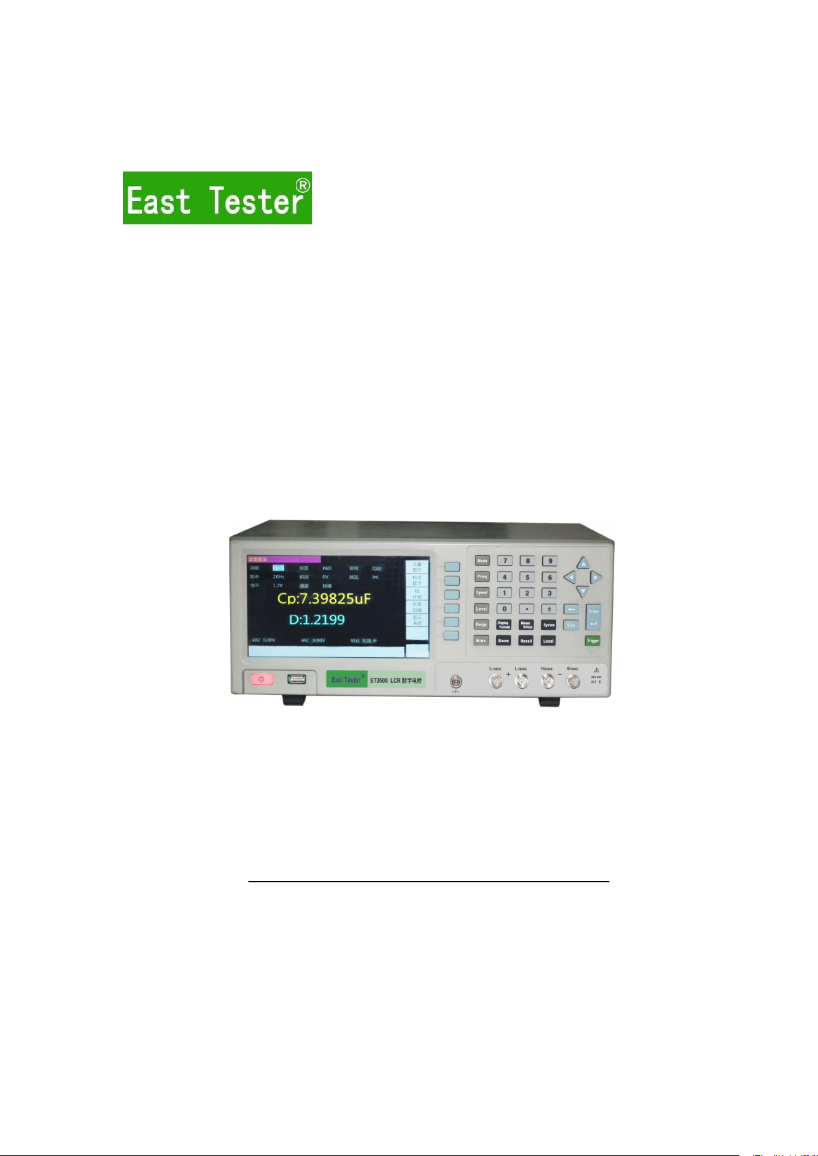
2.4 Screen area................................................................................................................ 7
2.5 Basic Operations....................................................................................................... 8
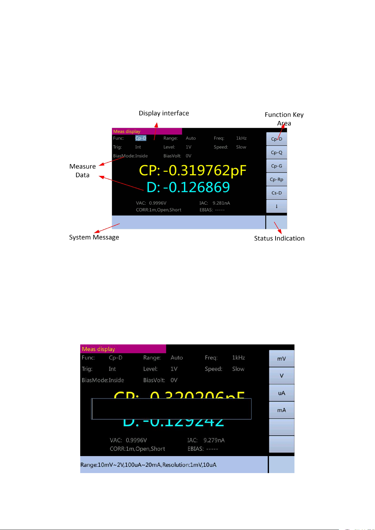
2.6 Display format............................................................................................................ 8
III. Basic measurement......................................................................................................... 13
3.1 Measurement Setup page..................................................................................... 13
3.2 Correction page....................................................................................................... 27
3.3 Limit table setup display.........................................................................................45
3.4 List Sweep Setup display.......................................................................................53
IV. System configuration....................................................................................................... 57
4.1 System configuration display................................................................................ 57
4.2 System configuration display................................................................................ 59
4.3 System self test....................................................................................................... 69
4.4 System update.........................................................................................................71
4.5 Self correction.......................................................................................................... 73
V. Save / call........................................................................................................................... 75
VI. Technical indicators and performance test.................................................................. 81
6.1 Technical indicators.................................................................................................81
6.2 Components.............................................................................................................93
6.3 General technical requirements............................................................................93
6.4 Performance test..................................................................................................... 94
VII. Instruction on the use of Handler interface................................................................ 97
VIII. Circuit theory and formulas........................................................................................103
IX. Notes and warranty....................................................................................................... 108

ET35 Series Digital Bridges(LCR)Operating Instructions
Hangzhou Zhongchuang Electron Co., Ltd.
1
I. Installation
This chapter describes the checks you should do after receiving the instrument and
the condition you should know and have before the installation.
1.1 Unpacking and checking
Thank you for purchasing and using our products; before you use the instrument,
please confirm in accordance with the last chapter “warranty” in the instructions.
Please contact us if there is discrepancy so as to safeguard your interest.
1.2 Power connection
(1) Voltage range of power supply: 220V.AC±10%,OR 110V.AC(optional).
(2) Frequency range of power supply: 50Hz ~ 60Hz.
(3) Power range: less than 20w.
(4) The input phase line L, the null line N, ground wire E of the instrument should be
the same as the power plugs.
(5) Although the instrument has been carefully designed to reduce the noise jamming
caused by AC power supply input, please use it in low-noise environments; if it cannot
be avoided, install the power supply filter.
Warning: To prevent the electric leakage which will cause harm to the instrument
or human beings, the user must ensure the reliable connection between the ground
wire of the power supply and the earth.
1.3 Fuse
The instrument is equipped with fuse before leaving the factory, and the user should use
the fuse provided by the company.
1.4 Environment
(1) Do not use it where there is dust, vibration, direct sunlight, or corrosive gas.
(2) Normal working temperature for the instrument 0°C ~ 40°C, humidity 15-85%, so
please try to use the instrument in this condition in order to ensure the accuracy of
measurement.
(3) Although the instrument has been carefully designed to reduce the noise jamming
caused by AC power supply input, please use it in low-noise environments; if it cannot
be avoided, install the power supply filter.

ET35 Series Digital Bridges(LCR)Operating Instructions
Hangzhou Zhongchuang Electron Co., Ltd.
2
(4) If the instrument will not be used for a long time, place it in the original packing box or a
similar box stored in a ventilated room with a temperature of 0°C ~ 4 °C and a relative
humidity of less than 85% RH. There should be no harmful impurities to corrode the
instrument, and direct sunlight should be avoided.
(5) Keep the instrument, especially the test lead wire connected to DUT away from strong
electromagnetic fields, so as to avoid interferance with the measurement.
1.5 Test fixture used
Please use the text fixture or test cable provided by the company. The text
fixture or test cable made by the user or other companies might lead to wrong
measurements. Keep clean the text fixture or test cable and pins of DUT to
ensure the proper contact of DUT with the fixture.
Connect the test fixture or test cable to the four test ends of the front panel
of the instrument—Hforce, Hsense, Lsense, and Lforce. For the DUT with
shield, connect the shielding layer with the instrument’s ground.
Note: an unstable measurement will be shown by the instrument without
installing the text fixture or test cable.
1.6 Preheating and continuous working time
(1) In order to ensure accurate measurement of the instrument, the
preheating time should be no less than 30 minutes; and continuous working
time should be no more than 16 hours.
(2) Do not frequently switch on and off the instrument; otherwise, it would
cause corruption of the internal data.
1.7 Other features of the instrument
1Power voltage: 220V.AC/50Hz ±10%,OR 110V.AC(optional)
2Power consumption: <20W
3Display: 7” TFT LCD, resolution 800*480
4Interfaces: LAN, RS232, GPIB, USB Host,USB Device and Handler
5Service environment: 0°C-40°C
6Sizes: 330mm*285mm*136mm (L*W*H)
7Weight: 3.6 kg

ET35 Series Digital Bridges(LCR)Operating Instructions
Hangzhou Zhongchuang Electron Co., Ltd.
3
II. Introduction to the product
This chapter describes the main features of the instrument, the front and back panels,
boot order and connection with the fixture.
2.1 Main Features
10Hz ~ 1MHz of test frequency
6 and a half digits of measurement resolution
Internal ± 2V of DC bias voltage
0.05% basic measurement accuracy
automatic, manual, external trigger and bus trigger measurement
dual measurement display
measurement in absolute form or reference value based deviation
measurement
accurate four-wire fixtures
categories of components
up to ± 60V of DC external bias voltage
internal memory
7-inch LCD color display
visual user interface, comprehensive test functions
providing RS232, HANDLER, GPIB, LAN, and USB Interfaces

ET35 Series Digital Bridges(LCR)Operating Instructions
Hangzhou Zhongchuang Electron Co., Ltd.
4
2.2 Introduction to the front panel
(1) Power switch
It is used to select the status of ET35 power supply (power on or power off). When
power is on, the switch is yellow-white, and all operating voltages are applied to the
instrument. When power is off, the switch is dark red, and no voltage is applied to the
instrument.
(2) 7-inch color screen
7-inch color screen displays measurement results, the test conditions, etc.
(3) Function keys
There are six function keys which are used to select the measurement conditions and
parameters. There is a mark on the left of each function key.
(4) Shortcut keys
There are six shortcut keys which are used to quickly select the measurement
conditions and parameters.
[MODE] key used for the selection and setting of the combination mode of the
measured objects
[FREQ] key used for the selection and setting of the measuring signal frequency
[SPEED] key used for the selection and setting of the measuring speed
[LEVEL] key used for the selection and setting of measuring signal level
[RANGE] key used for the selection and setting of range mode
[BIAS] key used for the selection and setting of internal voltage
(5) Menu keys
Menu keys are used to obtain the appropriate selection of instrument control.
[Display Format] key display the measurement results.

ET35 Series Digital Bridges(LCR)Operating Instructions
Hangzhou Zhongchuang Electron Co., Ltd.
5
[Meas Setup] key set measurement conditions, modification, limits of BIN
classification and List sweep parameters.
[System] key display the system information, set system parameters, self-test,
Self correction and upgrades.
[Save] key save, edit, or delete information, store measurements and screen
images.
[Recall] key load or delete information.
[Local] key lock or unlock the hardware and function keys on the current panel,
and change to the local mode.
(6) Arrow keys
The arrow keys are used to select the fields in the display page will move from one
field to another. When the cursor is moved to a field, the field will be changed to the one
opposite with the original video image. The cursor can only move between fields.
(7) Imput keys
Input keys for inputting the digital data to ET35. Enter key contains the digits 0 to 9,
decimal point (.), plus / minus (+/-), enter key and cancel key. Press the Enter key to
terminate the numeric input; presss the cancal key will nullify current input current; [←] key
to delete the character pointed by the cursor.
(8) Trigger key
Trigger key is used to manually trigger a measurement, and the key is valid only in
manual Triggering method.
(9) Test terminals
The test terminals are used to connect the four terminals of test fixture or test wire for
measuring DUT.
(10) USB Interface
The USB interface can be plugged in an external USB storage device, such as the U
disk, and store the data in USB memory.
(11) Ground terminal
The ground terminal is connected to the internal signal ground of the instrument, and
can be used for the shielding of the metal housing of the external test component.

ET35 Series Digital Bridges(LCR)Operating Instructions
Hangzhou Zhongchuang Electron Co., Ltd.
6
2.3 Introduction to the back panel
(1) GPIB interface connector
General Purpose Interface Bus (GPIB). Connecting an external controller and other
devices with the connector will constitute automatic measurement system. Note: GPIB
interface of ET3501 is optional.
(2) RS232C serial interface
With the serial communication interface, the instrument can be controlled by an
external PC.
(3) HANDLER interface connector
This interface can classify components with the automatic machine on the production
line.
(4) Ethernet interface
The interface connected to LAN (Local Area Network). Connect this instrument to the
LAN, and it can be controlled by an external PC.
(5) USB interface port
Connected to the PC's USB port. When this instrument is connected to the USB port
of the PC, the PC can be controlled by this instrument.
(6) External bias interface
The input port for the bias voltage in the external bias mode.
(7) Power interface
To connect the socket of the power supply, use the three-phase power cord with a
ground wire as provided.

ET35 Series Digital Bridges(LCR)Operating Instructions
Hangzhou Zhongchuang Electron Co., Ltd.
7
2.4 Screen area
This section describes the name and function of each part of the 7-inch color screen
of ET35.
Screen display
(1) Display area
It states the name on the display screen.
(2) Function key area
It shows the mark of the function key as corresponding to the field.
(3) Measurement data / condition area
It shows the current measurement condition and the measurement result.
(4) Input area
It shows the digital value input with the input key.

ET35 Series Digital Bridges(LCR)Operating Instructions
Hangzhou Zhongchuang Electron Co., Ltd.
8
(5) System message area
It shows the system messages, warnings and error messages.
(6) Status Indication
It shows any status of the front panel when it is locked.
2.5 Basic Operations
The basic operations of ET35 is described as follows:
1. Use the menu keys and function keys to display the desired page.
2. Use the arrow keys to move the cursor to the desired field. When the cursor is
moved to a specific field, the image of the field will be reversed. The cursor can move
between fields. For some common parameter settings, use shortcut keys to select the
desired field.
3. The mark of the function key pointed at by the cursor will be shown automaticlally.
Press the desired function key.
Use input keys to enter numeric data. Press the next input key, and the function key
will become the available unit function key. Press these unit function keys or Enter key will
stop the input of the data.
2.6 Display format
(1) Display of component measurement
Press [Display Format] key, and the screen will show the display of component
measurement. Users can set the following measurement on the display.
function
bias
range
frequency
offset
trigger
level
speed

ET35 Series Digital Bridges(LCR)Operating Instructions
Hangzhou Zhongchuang Electron Co., Ltd.
9
Steps of setting the function of measurement:
1. Press the [Display Format] key.
2. Press the [Measurement Display] key.
3. Use the arrow key to select the relevant parameter field such as "function" (part of
the common parameters can be set by selecting the corresponding function shortcut
key).
4. Use the function key to select the required parameter. (for the option requiring
number input, input the number and select with the function key).
(2) BIN Number Display
When you press the [Display Format] key and the [BIN Number Display] function key,
the page of BIN Number display will be shown. BIN classification is shown in large
character, and the measurement is shown in normal character. Users can set the
measurement control on the page
Comparator function on / off
The following information is also shown in the monitoring area on the page. These
conditions can be set on the measurement setting and correction setting page, and most
of the conditions can be set on the component measurement page.
function
bias
range
frequency
offset
trigger
level
speed
correction

ET35 Series Digital Bridges(LCR)Operating Instructions
Hangzhou Zhongchuang Electron Co., Ltd.
10
BIN Number Display
Comparator function ON / OFF
The internal comparator of ET35 can use up to nine pairs of primary parameter
limit and a pair of auxiliary parameter limit, and classify the device into up to 10 kinds
(binBIN1 ~ BIN9 and OUT OF BIN). In addition, the device with its first parameter
within the limit range and its auxiliary parameter measurement outside the limit range
can be classified as an auxiliary BIN (AUX BIN).
To use the comparator function to control device process, HANDLER interface is
required.
The above mentioned setting of limits for BIN classification can be done with the
[Meas Setup] on the page of limit list. Therefore, users to compare the filed only need
set the comparator function as on or off.
The step of setting the comparator function:
1. Press the [Display Format] key.
2. Press the [BIN Number Display] function key.
3. Use the arrow key to select "comp".
4. Use the function key to turn the comparator on or off.
(3) BIN Count page
Press the [Display Format] key and [BIN Count] function key, and the page of
BIN Count will be shown. The counting result of the comparator will be shown on the
page.
count function on / off
The following information is also shown in the monitoring area on the page.
These conditions can be set on the page of limit list.
function
nominal value

ET35 Series Digital Bridges(LCR)Operating Instructions
Hangzhou Zhongchuang Electron Co., Ltd.
11
BIN Count display
Counter function
BIN can be counted by ET35. ET35 can classify the components into the appropriate
BIN with the counter function when counting the components classified into each BIN.
999999. is the limit. When the count reaches the maximum value, counting stops and
the message of overflow "----" is shown.
Steps of setting the counter:
1. Press the [Display Format] key.
2. Press the [BIN Count] function key.
3. Use the arrow key to select the "count".
4. Use the function key to turn the comparator on or off.
Steps of clearing the counter:
1. Press the [Display Format] key.
2. Press [BIN Count] function key.
3. Use the arrow key to select the "Count".
4. Press the [Clear] function key.
(4) List sweep Display
When you press the [Display Format] key and [List sweep] function key, the List
sweep page will be displayed. The user can observe up to 10 points of test frequencies,
and measure the level or DC bias. The upper and lower limits can be set for each test
point for the List sweep. These test points are automatically swept and tested; the test
results will be compared with their corresponding limits. The limits cannot be set on this
page but on the List Settings display.
Users can set the sweep mode on this page

ET35 Series Digital Bridges(LCR)Operating Instructions
Hangzhou Zhongchuang Electron Co., Ltd.
12
List sweep Display
Sweep mode
The List sweep function of ET35 supports up to 100 settings of measurement frequency,
test signal level and DC bias. List sweep is done in two ways: sequential mode and
stepping mode. In sequential mode, every time ET35 triggers, all the sweep points are
automatically swept. In stepping mode, every time ET35 triggers, the sweep points will be
swept individually.
The steps of setting the Sweep mode:
1. Press the [Display Format] key.
2. Press the [List sweep] function key.
3. Use the arrow key to select "Sweep mode".
4. Use the function key to select the Sweep mode.
Note: ET35 will conduct one measurement on the component and compare the
results with the corresponding limits of each point when two or more set sweep points are
the same or near.

ET35 Series Digital Bridges(LCR)Operating Instructions
Hangzhou Zhongchuang Electron Co., Ltd.
13
III. Basic measurement
3.1 Measurement Setup page
Press the [Meas Setup] key to open the Measurement Setup page.
Measurement Setup page
In the measurement setup page, the user can move the cursor to the corresponding
field to configure all of the following measurement control functions.
test function (function)
option of internal and external DC bias (bias)
test range (range)
test frequency (frequency)
internal DC offset value (offset)
triggering method (trigger)
test level (level)
Test speed (Speed)
automatic level control (constant level)
delay time (delay)
output resistance (resistance)
deviation test A mode (deviation A)
deviation test B mode (deviation B)
deviation test A reference value (reference A)
deviation Test B reference value (reference B)

ET35 Series Digital Bridges(LCR)Operating Instructions
Hangzhou Zhongchuang Electron Co., Ltd.
14
Some settings on the measurement setup page are the same as the page of
component measurement shown as follows.
test function (function)
option of internal and external DC bias (bias)
test range (range)
test frequency (frequency)
internal DC offset value (offset)
triggering method (trigger)
test level (level)
test speed (Speed)
3.1.1. Triggering method
ET35 has the following four kinds of triggering methods: INT (internal trigger), MAN
(manual trigger), EXT (external trigger) and BUS (bus trigger).
When the triggering method is set to INT mode, ET35 continuously repeat the test.
When the triggering method is set to MAN mode, each time you press the [TRIG] key
on the front panel, ET35 conducts a test.
When the triggering method is set to EXT mode, every time HANDLER interface
receives a positive pulse, ET35 conducts one measurement.
When the Triggering method is set to BUS mode, every time ET35 receives the
trigger command from GPIB, it conducts one measurement.
Note: When ET35 is testing and receives a trigger signal, the trigger signal will be
ignored. Therefore it is required sending trigger signals after the test is completed by
ET35.
When the HANDLER interface triggers ET35, the triggering method is set to EXT
mode.
The triggering method can be set in the pages of component measurement and
measurement setup.
The steps of setting the triggering method:
1. Press the [Meas Setup] key.
2. Use the arrow key to select "Trigger", and press the [Enter] key.
3. Press the corresponding function key to select the desired triggering method.
Function keys:
INT (internal trigger)
MAN (manual trigger)
EXT (external trigger)
BUS (bus trigger)

ET35 Series Digital Bridges(LCR)Operating Instructions
Hangzhou Zhongchuang Electron Co., Ltd.
15
The page is shown below
3.1.2 Measurement Speed
The measurement speed of ET35 mainly depends on the following factors:
integration time (A / D conversion)
average number
measurement delay
measurement display time
ET35 has four different measurement speeds: slow, medium, fast and customized.
The faster the speed is, the lower the accuracy is; conversely, the slower the speed is, the
higher the accuracy is.
The measurement speed can be set in the pages of component measurement and
measurement setup.
The steps of setting measurement time
1. Press the [Meas Setup] key.
2. Use the arrow key to select "Speed" and press the [Enter] key.
3. Press the corresponding function key to select the desired measurement time. If
“Customized” is selected, then enter the proper number to set up the measurement time.
4. You can use the function key to enter the unit (us, ms, and s), press the [Enter] key
to select the default unit s.
Function keys:
FAST (Fast)
MED (medium speed)
SLOW (Slow)
Customized (user-set time)

ET35 Series Digital Bridges(LCR)Operating Instructions
Hangzhou Zhongchuang Electron Co., Ltd.
16
The page is shown below
Select [Customized] display
3.1.3 Measurement function
Two parameters of the impedance component can be simultaneously measured in
each cycle by ET35: main parameter and auxiliary parameter.
Main parameters
| Z | (impedance module)
| Y | (admittance module)
G (conductance)
Ls, Lp (inductance)
Cs, Cp (capacitance)
Rs, (resistance)

ET35 Series Digital Bridges(LCR)Operating Instructions
Hangzhou Zhongchuang Electron Co., Ltd.
17
Auxiliary parameters
D (dissipation factor)
Q (quality factor)
G (conductance)
Rp, Rs, Xs (resistance)
θr, θd (impedance angle)
B susceptance
The measurement function can be set in the pages of component measurement and
measurement setup.
Steps of setting the measurement function
1. Press the [Meas Setup] key
2. Use the arrow key to select the "Function", and press the [Enter] key
3. Press the corresponding function key
Function keys: Cp-D, Cp-Q, Cp-G, Cp-Rp, Cs-D, Cs-Q, Cs-Rs, Lp-D, Lp-Q, Lp-G,
Lp-Rp, Ls-D, Ls-Q, Ls-Rs, Rs-Xs, |Z|-θr, |Z|-θd, |Y|-θr, |Y|-θd, G-B.
The page is shown below
Press the [↓] function key and the page is shown below
This manual suits for next models
4
Table of contents
Other East Tester Measuring Instrument manuals
Popular Measuring Instrument manuals by other brands

Milwaukee
Milwaukee 48-22-9802 Operator's manual

Niigata seiki
Niigata seiki TVC-15S instruction manual

Polimaster
Polimaster PM 1703M-O Operation manual

Armstrong Monitoring
Armstrong Monitoring AMC-1040 Installation and operating instructions

THORLABS
THORLABS HNL020R user guide

PCB Piezotronics
PCB Piezotronics IMI SENSORS M627A01 Installation and operating manual