East Tester ETX-2710 User manual

ETX-2710 Temperature Calibrator
ETX-1710 Temperature Calibrator
Users Manual
Hangzhou Zhongchuang Electron Co., Ltd.

Contents
1 Basic Introduction........................................................................................................... 1
1.1 Function............................................................................................................... 1
1.2 Summary of Source and Measure Functions....................................................... 1
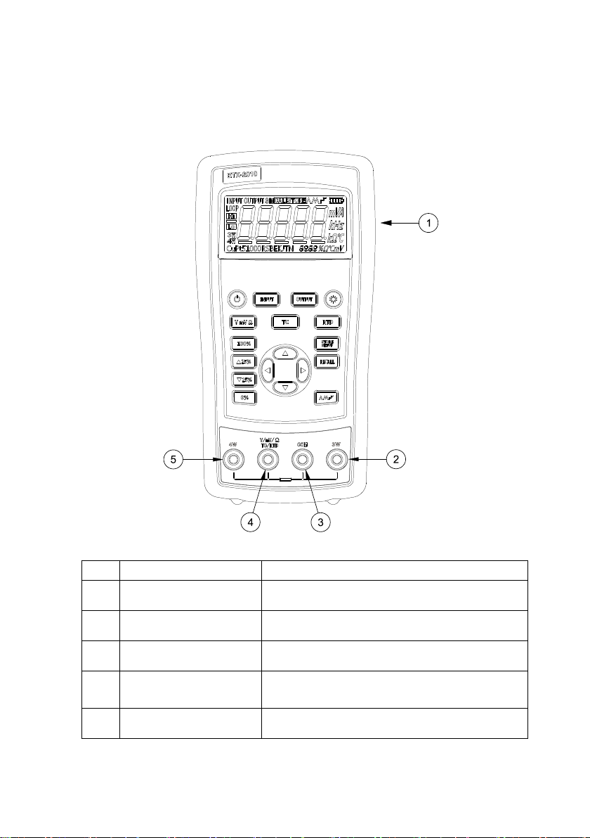
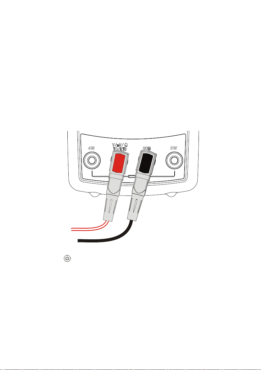
1.3 Terminal Description............................................................................................2
1.4 Key Description................................................................................................... 3
1.5 Display Screen..................................................................................................... 4
2 Basic Operation...............................................................................................................5
2.1 Measure and Source............................................................................................. 5
2.2 Shutdown Mode................................................................................................... 7
2.3 Backlight Brightness Adjustment.........................................................................8
3 Function Usage............................................................................................................... 9
3.1 DC V Measurement..............................................................................................9
3.2 DC mV Measurement........................................................................................ 10
3.3 Resistance Measurement....................................................................................10
3.4 DC mV Output................................................................................................... 11
3.5 Resistance Output.............................................................................................. 12
4 Temperature Measurement............................................................................................13
4.1 Using Thermocouple (TC)................................................................................. 13
4.2 Using Resistance Thermometer Detector (RTD)............................................... 15
5 Simulation of temperature sensor................................................................................. 18
5.1 Simulating Thermocouples................................................................................ 18
5.2 Application of Resistance Temperature Detector (RTD)................................... 19
6 Advanced Application................................................................................................... 21
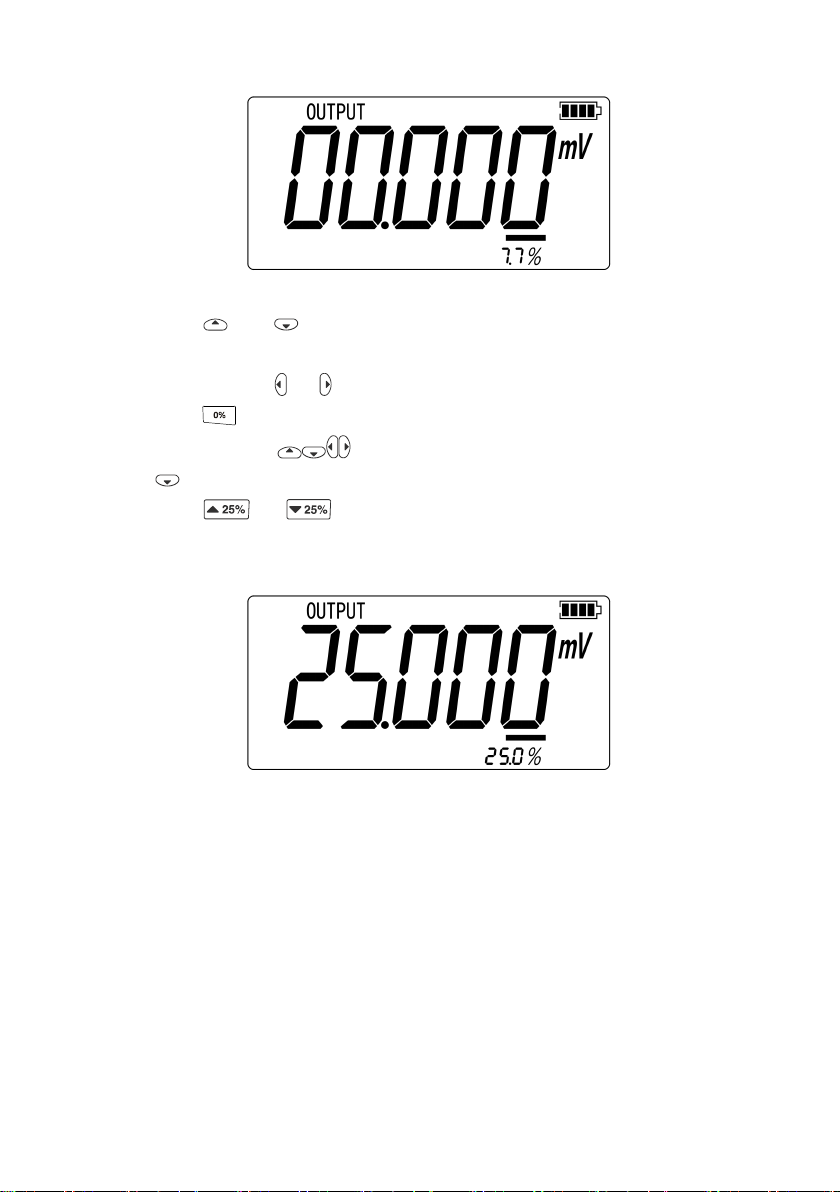
6.1 Setting 0 % and 100 % output parameters......................................................... 21
6.2 Auto Ramping the Output.................................................................................. 22
6.3 Factory Reset......................................................................................................22
7 Power............................................................................................................................ 23
7.1 Charge................................................................................................................ 23
8 Specifications................................................................................................................ 24
8.1 DC Voltage Measurement.................................................................................. 24

8.2 DC Voltage Source.............................................................................................24
8.3 Resistance Measurement....................................................................................25
8.4 Resistance Output.............................................................................................. 25
8.5 Temperature, TC.................................................................................................26
8.6 Temperature, RTD..............................................................................................27
9 Product Accessories...................................................................................................... 28
9.1 Standard Accessories..........................................................................................28
9.2 Optional accessories...........................................................................................28
10 Warning....................................................................................................................... 29

1
1 Basic Introduction
1.1 Function
It allows you to measure DC V, DC mV, resistance ,TC and RTD.
Outputs resistance, simulation of TC and RTD.
Thermocouple(TC) measurement provides cold-junction compensation.
Manual stepping, automatic stepping, 0~100% phase step and ramp output.
Super-strong protection :The waterproof grade is IP67. Automatic protection
against the signal terminals connect to the 220V.
Support for PC communication
1.2 Summary of Source and Measure
Functions
Function
Measure
Source
DC V
0~30V
Not available
DC mV
0~120mV
0mV~100mV
Resistance
0~3200Ω
0~3200Ω
RTD
Pt100, Pt1000, Cu50, Cu100
TC
E,J,K,T,B,R,S,N
E,J,K,T,B,R,S,N
Others
Stepping output, ramp, phase step output, user-defined range

2
1.3 Terminal Description
Figure 1.3-1
No.
Name
Description
①
Communication and charging
connector
Connect power adaptor to charge batteries or connect the
calibrator to the computer.
②
3W and 4W terminal
3-wire and 4-wire electric and thermal resistance
measurement terminal.
③
COM Public terminal
terminal
All measurement and output public terminal.
④
V, mV, Ω,TC and RTD
terminal
Voltage and DC mV, 2-wire resistance, thermal-electric
and resistance measurement as well as DC mV, resistance,
thermocouple and thermal-resistance output terminal.
⑤
4W+ terminal
Resistance and thermal resistance 4-wire measurement
terminal.

3
1.4 Key Description
Figure 1.4-1
No.
Description
①
Turns the power on or off
②
Selects the measurement mode
③
Selects output and analog transmitter mode.
④
Enables backlight switch display during start, enters backlight
brightness control mode.
⑤
Selects thermal resistance mode
⑥
Sets and saves calibrator parameters setting

4
⑦
Recovers factory default setting
⑧
Sets manual output
⑨
Cycles through:
slow repeating 0%-100%-0% ramp
Fast repeating 0 % - 100 % - 0 % ramp
Repeating 0 % - 100 % - 0 % ramp in 25 % steps
⑩
Set output by 0% of span, Press and hold to store the source value
as the 0 % value
⑾
Decrements output by 25% of span.
⑿
Increments output by 25% of span.
⒀
Sets output by 100% of span, Press and hold to store the source
value as the 100 % value.
⒁
Sets voltage, DC mV and resistance mode
⒂
Selects thermo-couple mode
1.5 Display Screen
Figure 1.5-1

5
2 Basic Operation
2.1 Measure and Source
This section acquaints you with some basic operations of ETX-2010/ ETX-1810.
Proceed as follows:
1. The connection of the calibrator as shown in Figure 2.1-1.
Figure 2.1-1
2. Press more than 2 seconds to turn on the calibrator. The calibrator checks
itself, including check on internal circuit and LCD, during which, LCD displays
all contents for 1s as shown in Figure 2.1-2:

6
Figure 2.1-2
3. Then the product model(2010)and automatic shutdown time(30 min)will
be displayed for 2 seconds as shown in Figure 2.1-3.
Figure 2.1-3
4. Then the default interface of boot will be displayed as shown in Figure 2.1-4:
Figure 2.1-4
5. Press , switch to the voltage mode. Switching is not required for this series
after starting-up.
6. Press to enter into output mode selection
7. Press to enter into DC mV output mode as shown in Figure 2.1-5.

7
Figure 2.1-5
8. Press and to increase or decrease 1 of the horizontal line position (the
number will be based on automatic stepping without change of horizontal line
position); press or to change the position of horizontal line.
9. Press until the buzzer works and to enter 0mV as 0% value.
10. Likewise, press to increase output value to be 100mV, and then press
until the buzzer works and enter 100mV as 100% value.
11. Press or to make output increase or decrease within the span of
0% to 100% based on 25% advance amplitude. The screen will display as shown
in Figure 2.1-6.
Figure 2.1-6
2.2 Shutdown Mode
The calibrator comes with the shutdown mode enabled for a time duration set to 30
minutes (displayed for about 2 seconds when the calibrator isinitially turned on). When
the shutdown mode is enabled, the calibrator will automatically shutdown after the
time duration has elapsed from the time the last key was pressed. To disable the

8
shutdown mode, press and simultaneously. To enable the mode, press
and simultaneously. To adjust the time duration, press and
simultaneously, the screen will display as shown in Figure 2.2-1,then press and/or
to adjust the time between 1 and 30 minutes and then press to store the
new time duration (Without pressing any key for 5 seconds, the calibrator will quit
from the adjustment automatically).
Figure 2.2-1
2.3 Backlight Brightness Adjustment
To adjust the brightness of backlight, proceed as follows:
1. Please press and simultaneously until the buzzer work, then the screen
will display as shown in Figure 2.3-1:
Figure 2.3-1
2. Press and to adjust the brightness of backlight.
3. Press to save brightness level, will appear and then the calibrator
will enter into the work mode(Without pressing key for 5 seconds, the calibrator
will exit from the adjustment automatically).

9
3 Function Usage
3.1 DC V Measurement
The default function after turn on is DC V measurement. If it is required, press
to re-select the voltage measurement (the display unit is V).Please connect the lines
after all functions are selected. The connection mode and interface are shown in Figure
3.1-1:
Figure 3.1-1

10
3.2 DC mV Measurement
Press to re-select the DC mV function (the display unit is DC mV), the
connection mode is same to that of voltage measurement. The screen will display as
shown in Figure 3.2-1.
Figure 3.2-1
3.3 Resistance Measurement
Press to reselect the DC mV measurement function (Display unit is Ω)
Figure 3.3-1
The Over Span Under Open Circuit
Resistance measurement supports the connection type of two-wire system, three-wire
system and four-wire system. The calibrator can be switched to three-wire system or
four-wire system according to actual connecting type. The respective connecting types
are listed in Figure 3.3-2: Press and to select the connection mode forcibly.

11
Figure 3.3-2
Press or to force the calibrator to adopt two-wire system, three-wire system
or four-wire system. Afterwards, the calibrator will not detect connecting type
automatically unless you quit the mode of resistance measurement and re-enter.
3.4 DC mV Output
Press and to select DC mV output function, the connection mode is
same to that of voltage measurement. The screen will display as shown in Figure 3.4-1.
Figure 3.4-1

12
3.5 Resistance Output
Press and to select the resistance output function, the connection mode
is same to that of voltage measurement.
Figure 3.5-1
indicates the undersize of exciting current,
meanwhile, the main value flashes
Press to select resistance output at 3200Ω level.
Figure 3.5-2
indicates the oversize of exciting current,
meanwhile, the main value flashes

13
4 Temperature Measurement
4.1 Using Thermocouple (TC)
The calibrator supports eleven standard thermocouples, including J, K, T, E, R, S, B, L,
U and N. Lower table summarizes the ranges and characteristics of the supported
thermocouples
Graduation
Positive lead
material
Positive wire (H)
color
Negative lead
material
Specified
span℃
ANSI*
IEC**
E
Chrome-nickel
Mauve
Purple
Constantan
-200~950
N
Nickel-chrome
-silicon
Orange
Pink
Nickel-silicon-magne
sium
-200~1300
J
Iron
White
Black
Constantan
-200~1200
K
Chrome-nickel
Yellow
Green
Alumel
-200~1370
T
Copper
Blue
Brown
Constantan
-200~400
B
Platinum (30%
rhodium)
Grey
Platinum (6%
rhodium)
600~1800
R
Platinum (13%
rhodium)
Black
Orange
Platinum
-20~1750
S
Platinum (10%
rhodium)
Black
Orange
Platinum
-20~1750
* Negative conductor (L) regulated as American National Standard (ANSI) is always red.
*Negative conductor (L) regulated as International Electro-technical Commission (L) is always white.
To measure temperature using thermocouple, the following steps shall be followed:
1. Connect the thermocouple to the calibrator as shown in Figure 4.1-1:

14
Figure 4.1-1
Attention:
Under different calibrator-thermocouple temperature environment, you shall
wait for one minute to stabilize the plug temperature after connecting TC to
input & output wiring.
2. Press to select measurement mode.
3. Press to display thermocouple reading as shown in Figure 4.1-2. If
necessary, pressing continuously to select appropriate thermocouple type.
Figure 4.1-2
4. Press to display the DC mV value reading as shown in Figure 4.1-3. The
DC mV value continue to display for 3s and then automatically return to the
original display .
Process temperature

15
Figure 4.1-3
There are two kinds of cold end temperature compensation for thermocouple
measurement, automatic compensation directly using machine internal cold end
temperature compensation and manual compensation through the key to set the cold
end temperature compensation by the user.
4.1.1 Automatic compensation
First entered the thermocouple measurement mode, the default of the cold end
temperature compensation is automatic compensation reading as shown in Figure
4.1.1-1.The sign represents that the current cold end temperature
compensation is automatic compensation. If you need further view current automatic
cold end temperature compensation value,you have to operation key. Reading
as shown in Figure 4.1.1-1,after press key, the sign is replaced for
current automatic cold end temperature compensation value as . The value
continue to display for 2s and then automatically return to the sign.
Figure 4.1.1-1

16
4.1.2 Manual compensation
Manual compensation through the key to set the cold end temperature compensation by
the user, the following steps shall be followed:
1. Press key to enter the set mode, reading as shown in Figure 4.1.2-1, the
appear of sign shows that entering the setup mode, the assistant value
means the value of manual compensation.
Figure 4.1.2-1
2. If you need to adjust the manual compensation value, press keys to
adjust.
3. Press key to save the value of manual compensation and exit from the
setup mode at the same time, reading as shown in Figure 4.1.2-2.
Figure 4.1.2-2
4. If necessary, press key return to automatic compensation.

17
4.2 Using Resistance Thermometer Detector
(RTD)
The calibrator accepts Pt100, Pt1000, Cu50 and Cu100, etc. The calibrator accepts
RTD measurements inputs in two-, three-, or four-wire connections, with the
three-wire connection the most common. A four-wire configuration provides the
highest measurement precision, and two-wire provides the lowest measurement
precision.
To measure temperature using an RTD input, proceed as follows:
1. Press to select mode.
2. Press for the RTD display. Then the screen will display as shown in
Figure 4.2-1. If desired, continue pressing this key to select the desired RTD
type.
3. Connect RTD to the corresponding port according to the connecting type of
‘resistance measurement’.
Figure 4.2-1
This manual suits for next models
1
Table of contents
Other East Tester Measuring Instrument manuals
Popular Measuring Instrument manuals by other brands

Milwaukee
Milwaukee 48-22-9802 Operator's manual

Niigata seiki
Niigata seiki TVC-15S instruction manual

Polimaster
Polimaster PM 1703M-O Operation manual

Armstrong Monitoring
Armstrong Monitoring AMC-1040 Installation and operating instructions

THORLABS
THORLABS HNL020R user guide

PCB Piezotronics
PCB Piezotronics IMI SENSORS M627A01 Installation and operating manual