3
Content
1
Summary ........................................................................................................................... 4
1.1
Product Overview: ...................................................................................................................... 4
1.2
Denomination for Product .......................................................................................................... 4
1.3
Safety Notice: .............................................................................................................................. 4
2
Product brief ..................................................................................................................... 5
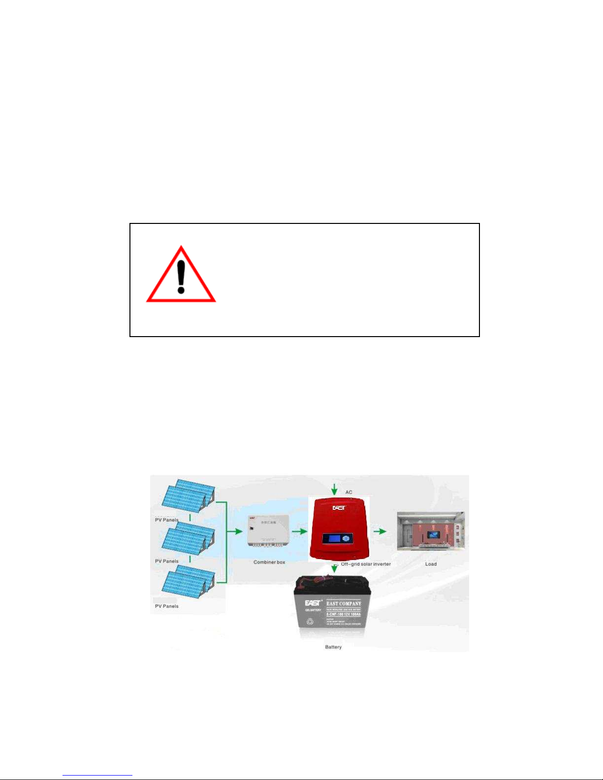
2.1
Solar system composition ........................................................................................................... 5
2.2
System Principle .......................................................................................................................... 6
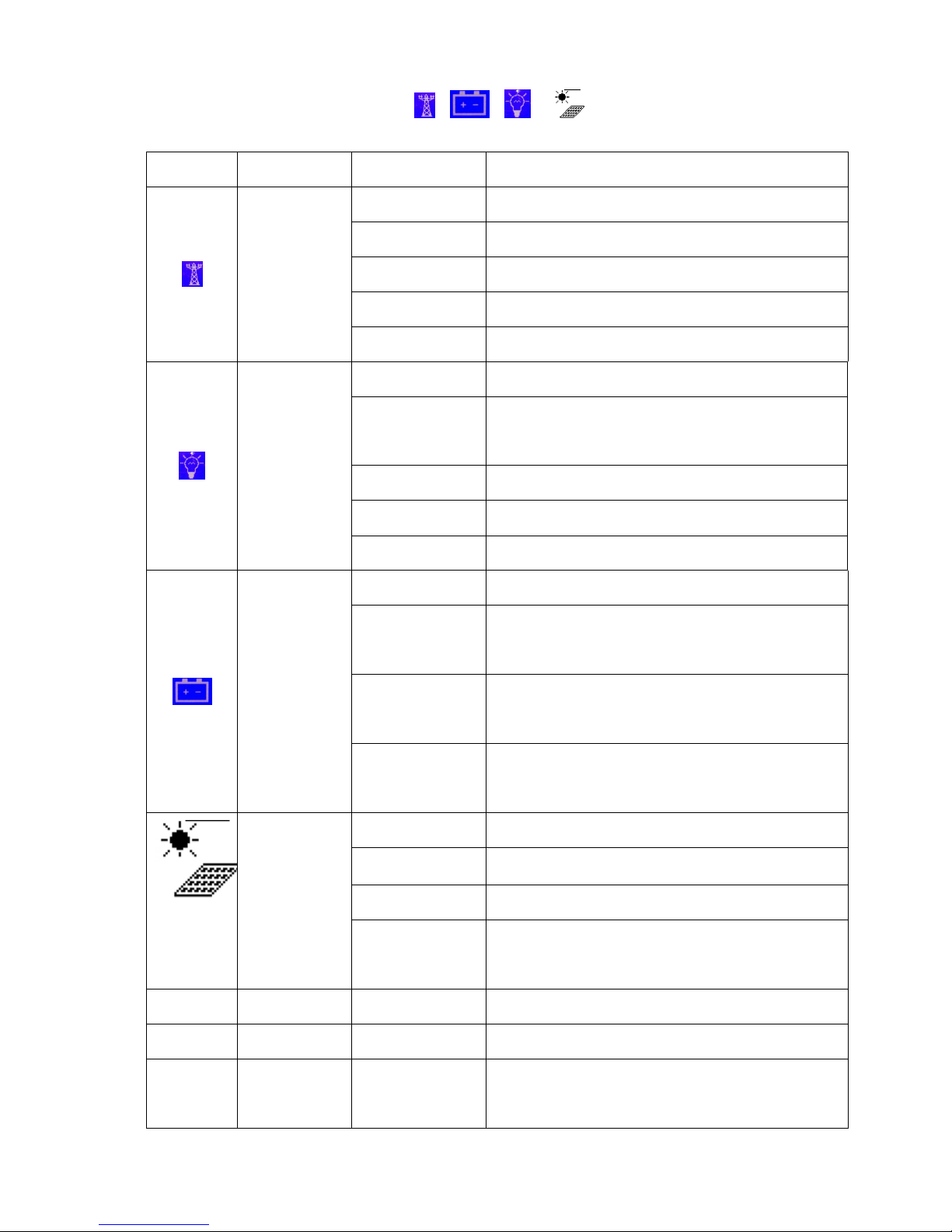
2.3
Product control description: ....................................................................................................... 6
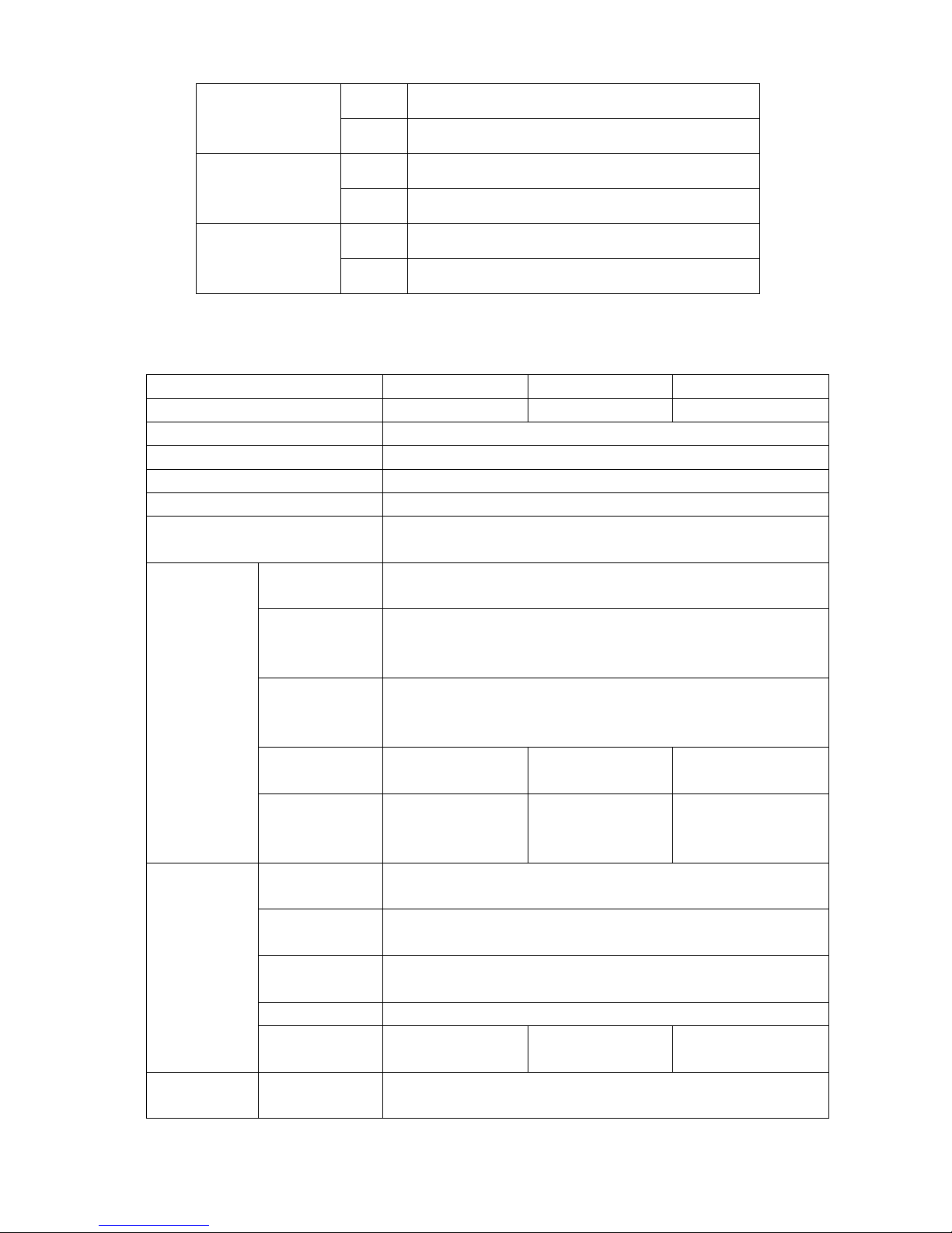
2.4
Tec nical specification: ............................................................................................................. 10
2.5
Working principle: .................................................................................................................... 12
2.5.1
Description: ..................................................................................................................... 12
2.5.2
“ANTI- FLOW BACK mode”: ............................................................................................. 12
2.5.3
Grid tied Mode ................................................................................................................ 13
3
Product storage and installation ................................................................................... 15
3.1
Product storage: ........................................................................................................................ 15
3.2
Installation ................................................................................................................................ 15
3.3
Installation site ......................................................................................................................... 16
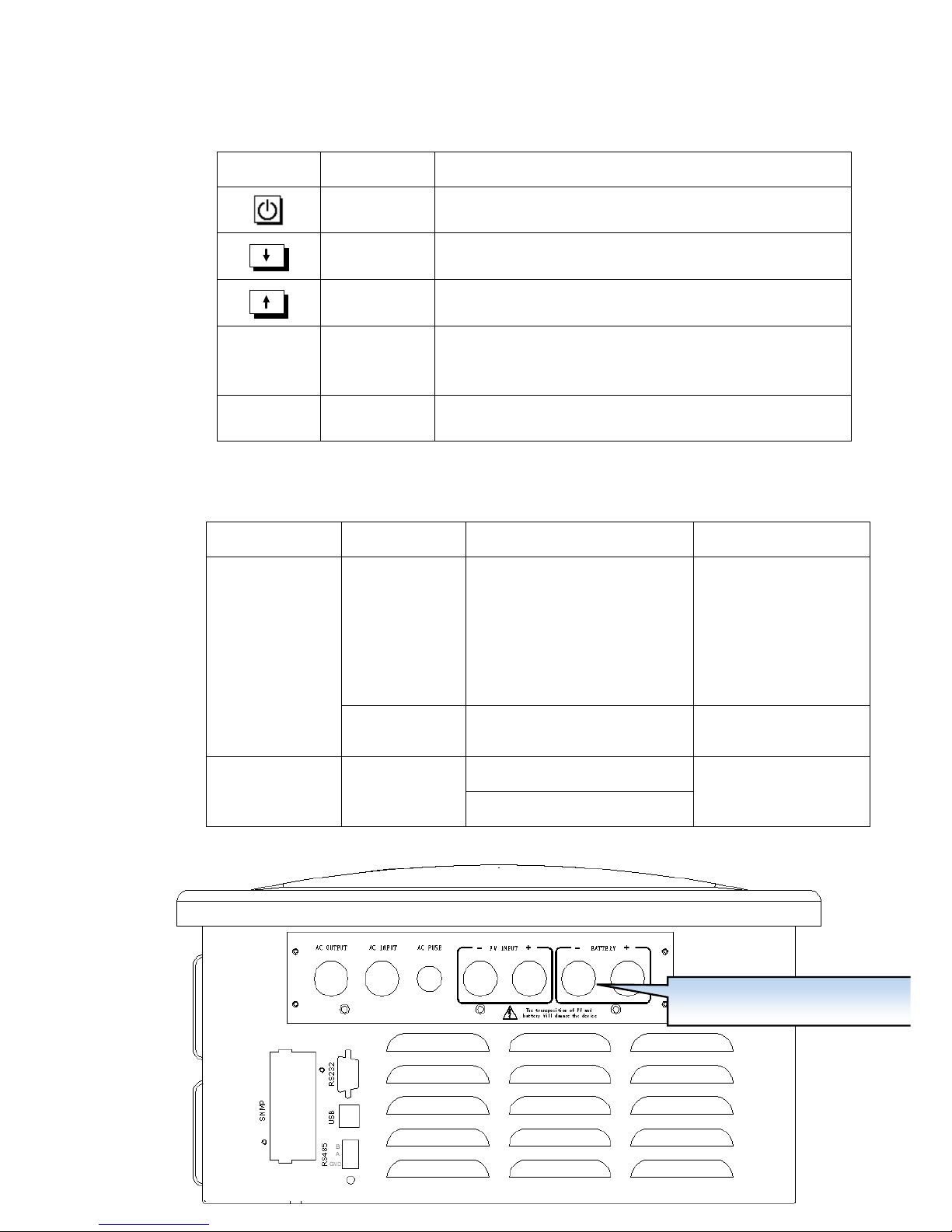
3.4
Cable connections ..................................................................................................................... 16
3.5
System connection: ................................................................................................................... 17
4
Operation Description .................................................................................................... 18
4.1
Daily switc ing on/off: ............................................................................................................. 18
4.2
For long time not using, switc ing on/off operation: ............................................................. 19
4.3
System information inquiry ...................................................................................................... 19
5
SYSTEM SET ..................................................................................................................... 20
5.1
LANGUAGE:
::
: ............................................................................................................................ 20
5.2
TIME SET .................................................................................................................................... 20
5.3
COM SET .................................................................................................................................... 20
5.4
PASSWORD SET ......................................................................................................................... 21
5.5
MODE SET ................................................................................................................................. 21
5.6
USER SET ................................................................................................................................... 22
5.7
ADVANCED SET.......................................................................................................................... 22
5.8
CONTRAST SET .......................................................................................................................... 23
5.9
FACEORY RSTET ......................................................................................................................... 23
6
Maintenance ................................................................................................................... 24
6.1
Preventive Maintenance .......................................................................................................... 24
6.2
Battery maintenance ................................................................................................................ 24
6.3
History records c eck and common problems solve ............................................................... 24
Appendix ......................................................................................................................... 26