East EA990G5 User manual

EAST GROUP CO., LTD.
EA990G5 10-30kVA (3/3)
Maintenance Manual
Prepared by Wu Zhifei / 20220830
Checked by Luo Changsheng / 20220831
Approved by Yang Lin / 20220831

i
Preface
General
This document provides maintenance requirement for high frequency three-input single-output
6-20KVA products, including safety precautions for maintenance, product description, description
on internal structure, description on composition of single boards, main components of single
boards, description on main functions, fault removal flow, replacement of single boards,
maintenance of single boards, and commissioning after maintenance, etc., to help an engineer to
provide technical support and maintenance service for three-input single-output 6-20K products.
User of document
This document (manual) is mainly applicable for the following engineers:
Technical support engineer
Maintenance engineer
Revision history
The revision history provides description on each document upgrade. The latest version of
document includes the upgraded content of all previous versions.
Document version: V01 (15 AUG 2014)
Formally issued for first time

Content
Preface.................................................................................................................................................. i
1 Safety precautions............................................................................................................................1
1.1 Hazards.................................................................................................................................... 1
1.2 Warning....................................................................................................................................1
2 Description of model........................................................................................................................2
2.1 Description of EA990G5 10-30kVA serial model...................................................................2
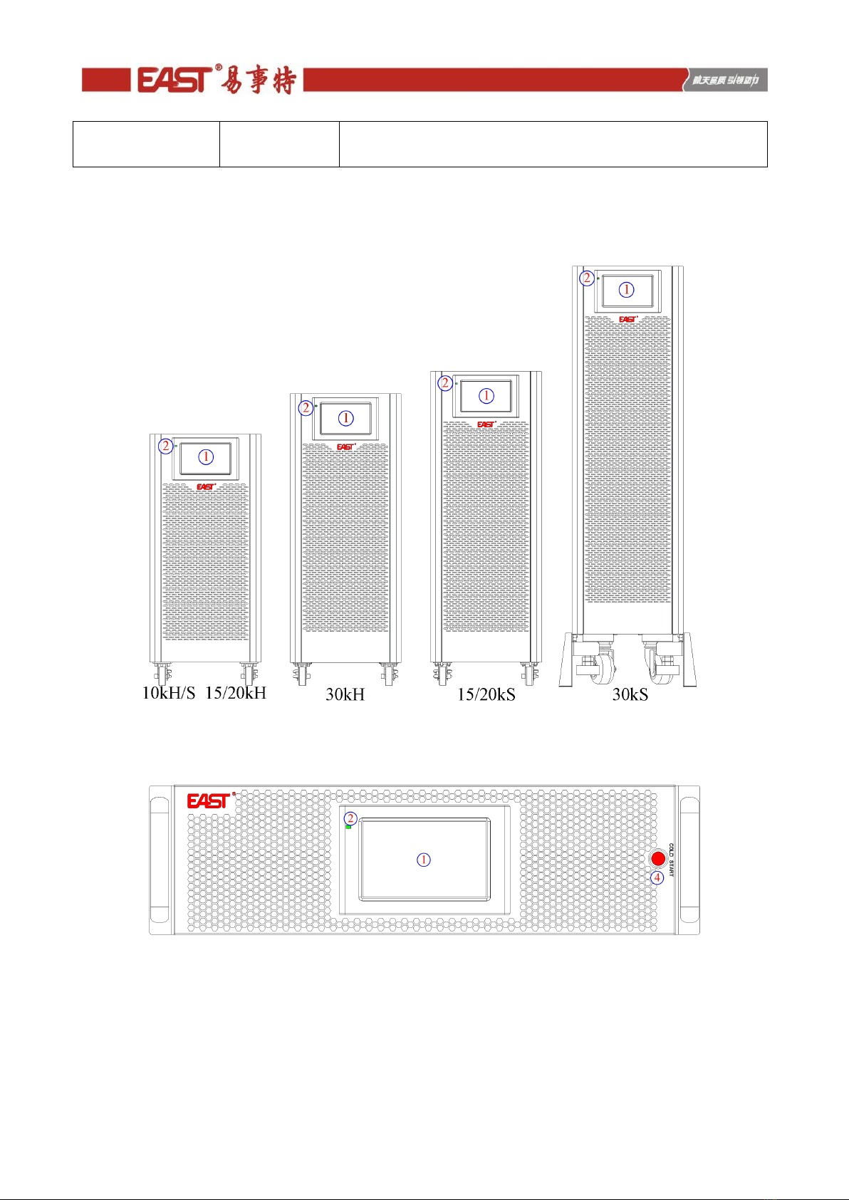
2.2 Appearance introduction of EA990G5 10-30kVA series model..............................................3
2.3 The operation control LCD panel introduction of EA990G5 10-30kVA................................ 6
3 Internal Introduction.................................................................................................................... 23
3.1 System Configuration............................................................................................................23
3.2 System Block Diagram..........................................................................................................26
3.3 Introduction to Internal Boards............................................................................................. 27
4 Troubleshooting............................................................................................................................. 28
4.1 Repair tool List...................................................................................................................... 28
4.2 Troubleshooting process........................................................................................................28
4.3 Alarm information collection................................................................................................ 30
4.4 Common faults and troubleshooting methods....................................................................... 30
4.5 Alarm detailed explanation and handling suggestions.......................................................... 30
5 Board replacement........................................................................................................................ 35
5.1 Board replacement of 10kVA model..................................................................................... 35
5.2 Board replacement of 15kVA model..................................................................................... 37
5.3 Board replacement of 20kVA model..................................................................................... 40
5.4 Board replacement of 30kVA model..................................................................................... 42
6 Board maintenance........................................................................................................................45
6.1 Maintenance of power board................................................................................................. 45
6.2 Maintenance of IP/OP board................................................................................................. 58
6.3 Maintenance of Bypass board............................................................................................... 66
7 Test.................................................................................................................................................. 72

7.1 Boards installation................................................................................................................. 72
7.2 Preparation before power-on................................................................................................. 72
7.3 Power-on and testing............................................................................................................. 72

1
1 Safety precautions
1.1 Hazards
1.As dangerous voltage exists in the UPS and the battery holder, installation and maintenance are only
completed by a professional engineer holding professional electrician qualification of the company or authorized
by the company.
2.Operators and maintainers, and professional technicians should receive full training on safe use and
equipment maintenance and work on the equipment after enough precautionary measures are taken and personal
safety equipment is used.
3.As the UPS is connected with the battery, voltage may exist on its output end even if it is not connected
with AC mains supply.
4.When the UPS is moved or rewired, the inputs, such as mains supply, the battery, etc., must be
disconnected, corresponding operation may be performed after the UPS powers down fully (more than 10min),
and otherwise the voltage may exist on its output end.
5.Before use, the UPS is reliably earthed to ensure personal safety and the normal use of the UPS.
6.When the UPS is maintained, the maintainer must wear insulated shoes and use insulated tools.
7.If temperature and humidity exceeds the limit value specified in the user manual, do not operate the
equipment.
8.Before maintenance of the UPS, all inputs and outputs of the UPS (including battery input) must be
disconnected.
9.Do not place the battery in fire to avoid explosion and endangering personal safety.
10.Do not stop the protector and ignore warnings, cautions and precautionary measures provided in the
manual and equipment nameplate.
1.2 Warning
1.Do not open the battery cover or damage the battery. If you are exposed to electrolyte, immediately wash
with plenty of clear water and seek medical advice.
2.Remove watch, ring and other metal article, wear insulating gloves and use the tools with insulated handle
during work on the battery.
3.During equipment operation, make sure that all sides and internal panels are securely fixed and front door
is closed.

2
2 Description of model
2.1 Description of EA990G5 10-30kVA serial model
Our EA990G5 10-30kVA series models are divided into tower type and rack type. The power level is
10/15/20/30KVA and the output power factor is 1.0. It can realize parallel operation of up to 4 units, provide
redundant power supply, and provide stable and reliable power supply for customer loads.
Table 2-1 EA990G5 10-30kVA serial model
Component
Model
Specification
Note
UPS
10kH
10kVA Long-delay Mode(Tower)
UPS
10kS
10kVA Standard Mode(Tower)
with ±10 12V/7AH internal
UPS
10kHRT
10kVA Long-delay Mode(Rack)
UPS
15kH
15kVA Long-delay Mode(Tower)
UPS
15kS
15kVA Standard Mode(Tower)
with ±20 12V/7AH internal
UPS
15kHRT
15kVA Long-delay Mode(Rack)
UPS
20kH
20kVA Long-delay Mode(Tower)
UPS
20kS
20kVA Standard Mode(Tower)
with ±20 12V/7AH internal
UPS
20kHRT
20kVA Long-delay Mode(Rack)
UPS
30kH
30kVA Long-delay Mode(Tower)
UPS
30kS
30kVA Standard Mode(Tower)
with two string ±15 12V/7AH internal
UPS
30kHRT
30kVA Long-delay Mode(Rack)
Table 2-2 Accessories of EA990G5 10-30kVA serial model
SNMP card/protocol
conversion
card(including
packaging materials)
iDA-ST200P
Remote network monitoring can be realized (RJ45 interface, as a
protocol conversion card, an adapter cable is required)
The built-in card is directly inserted into the card slot;
SNMP card/protocol
conversion
card(excluding
packaging materials)
iDA-ST200P
Remote network monitoring can be realized (RJ45 interface, as a
protocol conversion card, an adapter cable is required)
The built-in card is directly inserted into the card slot;
SMS cat
iDM-MDM200E
This device needs to be used with an SNMP card;
When the SNMP card detects that the UPS has an alarm, the SNMP
card can control the SMS modem to send the alarm content to the
mobile phone of the designated user;
It does not contain a SIM card and needs to be purchased separately.
At the same time, it only applies to standard SIM cards of China
Mobile and China Unicom.
SMS alarm
iDM-ALM200P
The alarm information of the UPS can be automatically sent to the
mobile phone of the designated user;
It does not contain a SIM card and needs to be purchased separately.
At the same time, it only applies to standard SIM cards of China
Mobile and China Unicom.
WIFI module
iDM-SPW202P
WIFI--glue stick antenna; you can connect the WIFIF module
through a mobile phone or computer to check the running status and
parameters of the UPS.
GPRS module
iDM-SPG203P
GPRS - glue stick antenna; you can connect the GPRS module

3
(external, DB9)
through a mobile phone or computer to check the running status and
parameters of the UPS.
2.2 Appearance introduction of EA990G5 10-30kVA series model
The overall appearance is shown in Figures 2-1 to 2-7 below.
Fig.2-1 The front pannel of 10-30kVA series UPS (Tower)
Fig.2-2 The front pannel of 10-30kVA series UPS (Rack)

4
Fig.2-3 The rear pannel of 10kVA, 15kVA, 20kVA long-delay UPS (Tower)
Fig.2-4 The rear pannel of 10kVA, 15kVA, 20kVA standard UPS (Tower)

5
Fig.2-5 The rear pannel of 30kVA UPS (Tower)
Fig.2-6 The rear pannel of 10kVA, 15kVA, 20kVA UPS (Rack)

6
Fig.2-7 The rear pannel of 30kVA UPS (Rack)
Table 2-3 The introduction of front and rear pannel
NO.
Part name
1
LCD screen
2
LED
3
Smart card slot
4
Cold start button
5
RS232 port
6
RS485 port
7
USB port
8
EPO
9
Parallel port
10
Dry contact port
11
Maintenance Bypass Assembly
12
Bypass breaker
13
Output breaker
14
Input breaker
15
Terminal block and cover
16
PE
17
Battery breaker
2.3 The operation control LCD panel introduction of EA990G5 10-30kVA
This chapter introduces the functions and operator instructions of the operator control and display panel in
detail, and provides LCD display information, including LCD display types, detailed menu information, prompt
window information and UPS alarm information.
2.3.1 LCD panel for Cabinet
The structure of operator control and display panel for cabinet is shown in Fig.4-1. The operation control
panel of UPS is located on the front panel of the case. By operating the LCD, the ups can be operated, controlled,
and checked for all its parameters, operating status, and alarm information.

7
Fig.2-8 Control and display panel
LED Indicator
There are 2 LEDs on the panel to indicate the operating status and fault.The description of indicators is
shown in table 2-4。
Table 2-4 Status description of indicators
Indicators
State
Description
red
Steady red
UPS fault
Flashing red
UPS alarming
green
Steady green
Power supply mode (mains mode, bypass mode, ECO mode, etc.)
No
None
Standby status or no starting
Alarm
There are two different types of audible alarm during UPS operation, as shown in table 2-5
Table 2-5 Description of audible alarm
Alarm
Description
Intermittent alarm
when system has general alarm (for example: AC fault),
Continuous alarm
When system has serious faults (for example: hardware fault)
LCD Menu structure
The menu structure of the monitoring display interface is shown in Fig.2-9

8
Fig.2-9 Menu
2.3.2 Home page
After the monitoring system starts self-test, the system enters the home page, following the
welcome window. The home page is divided into three parts, including main menu, energy flow
diagram, status bar. The home page is shown in Fig. 2-10.
Fig. 2-10 Home page
Table 2-6 Function description of interface area
No.
Area
Function description
1
Main menu
Level 1 menu, including home page, system, alarm, control,
settings, password login. The control and the settings are
displayed in gray before login by password.

9
No.
Area
Function description
2
Energy flow diagram
Display the energy flow state of the cabinet. Click the
corresponding work interface to view the status information.
3
Status bar
Display operation status, system time, buzzer status, alarm
status, HMI and monitoring communication status, USB status
of the cabinet.
4
Cold start
Start the UPS in battery mode. The icon will be hidden after two
minutes.
Table 2-7 Description of icons in status bar
Icon
Function description
Buzzer status, which becomes lit to indicate the buzzer enabled, and off to indicate the
buzzer disabled
Alarm status, which becomes lit to indicate an alarm, and off to indicate no alarm
Password login/logout key. After clicking, enter user password or advanced password
by the keyboard. The screen will be locked automatically.
Table 2-8 Description of password permissions
Password
permissions
Default
Function description
User password
123456
Unlock On and OFF control right and the right of common
settings and communication settings.
It can be changed in "settings - common settings - user
password".
Advanced
password
Not opened
Unlock all control and setting rights.
It can be used by qualified electricians only.
2.3.3 System
In the "System" information interface, the "Mains ", "Bypass ", "Battery ", "Output", "Other", "Statistics" and
"About " information of the system can be inquired in the secondary menu at the left side.
Mains
The menu interface of the mains input is shown in Fig. 2-11, and displays information on three phases ABC
from left to right. The interface description is shown in Table 2-9.

10
Fig. 2-11 Input interface
Table 2-9 Description of input interface
Display item
Description
Voltage (V)
Mains input phase voltage
Current (A)
Mains input phase current
Frequency (Hz)
Mains input frequency
PF
Mains input Power factor
Bypass
The menu interface of the bypass input is shown in Fig. 2-12, and the interface description is shown in Table
2-10.
Fig. 2-12 Bypass interface
Table 2-10 Description of bypass interface
Display item
Description
Voltage (V)
Bypass input phase voltage

11
Display item
Description
Current (A)
Bypass input phase current
Frequency (Hz)
Bypass input frequency
PF
Bypass input Power factor
Battery
The interface menu of battery input is shown in Fig. 2-13, and the interface description is shown in Table
2-11.
Fig. 2-13 Battery interface
Table 2-11 Description of battery interface
Display item
Description
Battery voltage
(V)
Battery voltage
Battery Current
(A)
Battery current
Battery status
Current battery status: idle, discharge, boost charge, floating charge, None
Temperature
(℃)
Current operating temperature of battery (optional battery temperature sensor,
display "NA" if not connected)
Backup time
(min)
Estimated discharge time of the battery at the current load
Remaining cap.
(%)
Current remaining capacity of battery
Output
The interface of output menu is shown in Fig. 2-14, and the interface description is shown in Table 2-12.

12
Fig. 2-14 Output interface
Table 2-12 Description of output interface
Display item
Description
Voltage (V)
AC output phase voltage.
Current (A)
AC output phase current.
Frequency (Hz)
AC output frequency.
Load ratio (%)
Load rate of each phase of the machine
Active power (kW)
Output active power of each phase of the UPS unit
Appa. pow. (kVA)
Output apparent power of each phase of the UPS unit
Reactive power(kVA)
Output reactive power of each phase of the UPS unit
PF
Output power factor of each phase of the UPS unit
Other
The interface of other menu is shown in Fig. 2-15, and the interface description is shown in Table 2-13.
Fig. 2-15 Other interface

13
Table 2-13 Description of other interface
Display item
Description
PFC temperature
Rectifier temperature
INV temperature
Inverter temperature
Environmental
temperature
Environmental temperature(optional battery temperature sensor,
display "NA" if not connected)
Statistics
The interface of statistics menu is shown in Fig. 2-16, and the interface description is shown in Table 2-14.
Fig. 2-16 Statistics interface
Table 2-14 Description of statistics interface
Display item
Description
Bypass runtime (min)
Accumulative operation time of UPS in bypass output status
Inv. Runtime (min)
Accumulative operation time of UPS in inverter output status
Last discharge
Date of previous discharge status of UPS
Batt. expire time
When the system time exceeds the warranty period, the status bar will
prompt the warranty information of battery.
UPS expire time
When the system time exceeds the warranty period, the status bar will
prompt the warranty information of main machine.
About
The interface of “About” menu is shown in Fig. 2-17, and the interface description is shown in Table 2-15.

14
Fig. 2-17 About interface
Table 2-15 Description of Interface
Display item
Description
S/N
Production serial number of this machine.
TEL
Contact information of after-sales service providers.
Manufacturer
Manufacturer of this machine.
Website
Website of manufacturer of this unit.
HMI version
Program version of HMI display system.
PFC1 version
Program version of power rectifier system
Inv.1 version
Program version of power inverter system
2.3.4 Alarm
In the "Alarms" information interface, you can view "Active alarm"and"Fault record "from the secondary
menu in the lower left corner. Click to select the type of alarm you want to view. The interface of alarm menu is
shown in Fig. 2-18.
Fig. 2-18 Alarm menu interface

15
Active alarm
The active alarm interface displays the relevant information of the current warning of UPS system, The
interface description is shown in Table 2.16.
Table 2-16 Description of active alarm interface
Display item
Description
No.
Alarm number
Location
Display the cabinet number and module number of the current alarm
source.
ID
Alarm code for program analysis.
Information
Current alarm name
Time
The current alarm is the current alarm information without time
display.
History records
The "history record" is divided into "Location ID ", "Information " and "Tine ", as shown in Fig.2-19, The
interface description is shown in Table 2-17.
Fig.2-19
Table 2-17 Description of history record interface
Display item
Description
No.
Record number, which is listed in reverse order, that is to say the latest
record is in the front.
Location
Displays the module number of the current record source.
ID
List code of fault, status or operation information for program analysis
Information
Current record name and record state (occurrence, disappearance).
Time
Record the time of occurrence or disappearance.

16
4.2.6 Control
In the "Control " information interface, you can select relevant operation from the left secondary menu,
which contains "On-Off "and "Maintain".
On-Off
The interface of the On-Off menu is shown in Fig. 2-20, and the interface description is shown in Table 2-18.
Fig. 2-20 On-Off interface
Table 2-18 Description of On-Off interface
Control item
Description
System on-off
Including “Inv.On”, “Shut to bypass” and “Shutdown”. It is gray
when clicking is invalid.
Manual to bypass
Including “On” and “Off”. It is gray when clicking is invalid.
If the bypass is abnormal, switching to bypass fails.
Maintenance
The interface of maintenance menu is shown in Fig. 2-21, and the interface description is shown in Table
2-19.
Table of contents
Other East UPS manuals