Eastey SB-2EX-SEMI User manual

SB-2/3EX-SEMI
Semi Automatic
Carton Sealing Machine
User Guide


SB-2/3EX-SEMI
Semi Automatic
Carton Sealing Machine
User Guide
Revised 02/20/2018
P/N 5001682 Rev D
Copyright and Trademarks
Copyright ©2012-2018 Eastey Enterprises
All rights reserved. All trademarks and brand names
are the property of their respective owners.
Eastey Enterprises, Inc.
7041 Boone Ave. N.
Brooklyn Park, MN 55428
Phone: (763) 428-4846; Fax (763) 795-8867; 1-800-835-9344
www.eastey.com


Contents
Safety .............................................................................................................................7
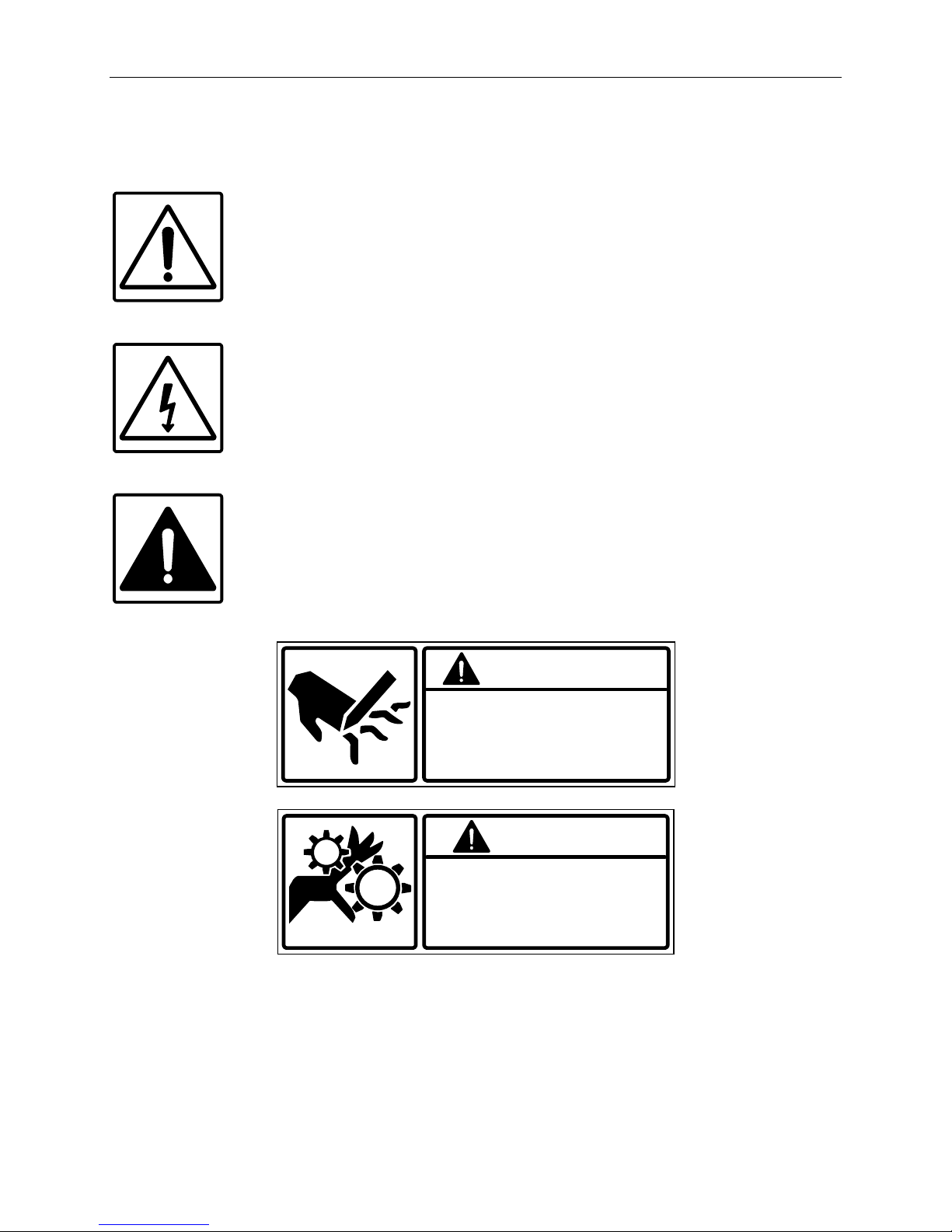
Explanation of Symbols.................................................................................................8
Introduction ...................................................................................................................9
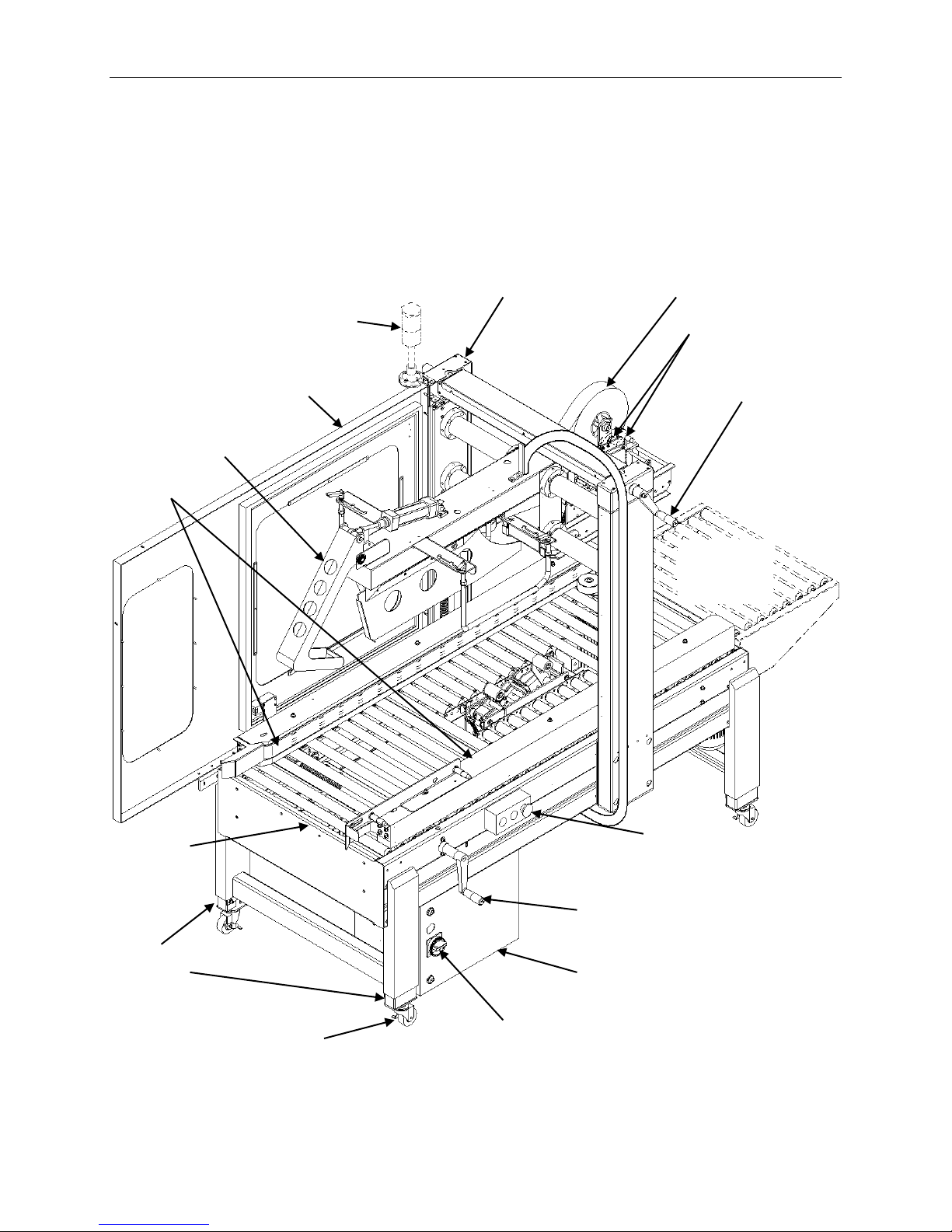
General System Description..........................................................................................9
Specifications..............................................................................................................10
Dimensions .................................................................................................................11
Installation ...................................................................................................................13
Location Requirements ...............................................................................................14
Operation.....................................................................................................................15
Loading the Tape Cartridges.......................................................................................15
Check Tension............................................................................................................16
Thread Tape................................................................................................................16
Main Spring.................................................................................................................18
Power..........................................................................................................................19
Control Panel ..............................................................................................................19
Adjustments ................................................................................................................21
Air Pressure unit..........................................................................................................21
Height and Width Adjustment......................................................................................22
Flap Closing Guide Adjustment...................................................................................23
Belt Adjustment...........................................................................................................25
Machine Body Height Adjustment ...............................................................................26
Maintenance ................................................................................................................27
Rollers.........................................................................................................................27
Cutting Knives.............................................................................................................27
Troubleshooting..........................................................................................................28
Parts List......................................................................................................................31
Electrical......................................................................................................................31
Pneumatic Parts..........................................................................................................35
Side Belt......................................................................................................................37
Column........................................................................................................................40
Flap Guide Assembly ..................................................................................................42
Machine Body .............................................................................................................45
Door Guard Assembly.................................................................................................47
Appendix A: Electrical Schematic .............................................................................49
Warranty Statement ....................................................................................................55
Customer Support.......................................................................................................57


Safety 7
Safety
General Safety Precautions
Before installing, operating or servicing this equipment, please read the following
precautions carefully:
This machine is equipped with moving belts. Do not place hands near the rear of this
unit when the belts are moving as fingers may be pinched where belts enter the
frame. We suggest the use of a roller-type exit conveyor or pack table for your
cases. Always remove boxes after they clear the exit end of the machine.
Observe caution when near the tape applying cartridges or when threading tape.
The knife is very sharp, automatically operated, and is linked to the wipe down
rollers.
Always disconnect electrical power before attempting maintenance for any electrical
or moving parts. Do not attempt to open or work on the electrical box, junction
boxes, or other electrical components of the unit without first disconnecting power to
the machine. Electrical shock hazard exists if power is not disconnected.
Do not by-pass any factory-designed safety features such as knife guards,
interlocks, switches, etc.
Do not place hands or body inside the confines of the machine unless the head
mechanism is securely fastened, and the electrical supply is shut off.
To minimize the potential for personal injury, always be sure that the machine
operators and others working on the machinery are properly trained in the correct
usage of the equipment and properly instructed regarding safe operation.
Never provide service or clear a box jam when machine is running.
When feeding a box into the unit, always hold down the box top and present the box
to unit. Release hands as soon as the belts begin to take the box.
Do not wear loose clothing such as ties, scarves, jewelry etc. Long hair should be
pulled back and/or covered while operating this machine.

8 Safety
Explanation of Symbols
Caution sign or Safety Alert symbol. Indicates caution, be alert, Your
safety is involved. Knowledge of safe operation is required.
Caution indicates a hazardous situation which, if not avoided, could
result in minor or moderate injury or damage to equipment or
surroundings.
Electrical hazard. Indicates electrical danger. Only a trained electrician
can uncover the electrical panel or box.
Warning symbol. Indicates a hazardous situation which, if not avoided
could result in death or serious injury.
A warning indicates a situation or condition potentially more severe than
indicated by a caution message but not imminent as a danger message.
This symbol is associated with warnings for conditions as shown below.
DO NOT TOUCH THE BELT
WHEN THE MACHINE
IS RUNNING
WARNING
BLADE MAY CUT
YOUR FINGER
WARNING

Introduction 9
Introduction
General System Description
Flap Folding
Assembly
Tape Head
Height
Adjustment
Crank
Width
Adjustment
Crank
Electrical
Box
Adjustable
Legs
Drive
Belt
Control panel with
Start/Run and
Stop buttons, and
Emergency Stop
Switch (E-Stop)
Optional
Alarm Signal
Light Stack
Guard Doors —
Panels for near side
shown removed.
Main Power
Switch
Optional
Tape Low / Out
Sensors
Vertical
Column
Infeed
End
Optional
Exit End
Roller Table
Locking
Casters

10 Introduction
Specifications
Model
SB-2/3EX-SEMI
Tape
1.5 inches or 2 inches
Belt speed
75 ft/min
Capacity
(L) 4.7 to 24 inches
(W) 4.3 to 19.5 inches
(H) 4.7 to 19 inches
Consumption
450 W
Machine size
With Guard Doors
(L) 84 inches
(W) 35.5 inches
(H) 66.1 inches
Machine Frame Length
(L) 66 inches
Machine net weight
660 lbs.
Air
80 psi
Electrical
Belt motor
0.18KVA
Machine power use
0.4KVA
Power socket need
0.5KVA
Options
3” tape head
Infeed end roller table
Exit end roller table
Tape low/out sensing with alarm signal light stack

Introduction 11
Dimensions
Dimensions shown in inches.
Guards
Extend
18 in.
Beyond
Infeed End.
66 in. Machine Roller Table Length
84 in.
Overall Standard Machine Length with Guards
35.5 in.
30 in. 24.5 in.
66.1 in.
Floor to
Top of
Column
Max.
27 in. Min. Roller
Height
to
34.5 in. Max.

12 Introduction
Dimensions —with Optional Roller Tables and Tape Low / Out Sensors
and Alarm Signal Light Stack
Dimensions shown in inches.

Installation 13
Installation
Carefully unpack the outer carton. Avoid damaging the machine body.
Remove the banding straps that secure the carton sealer to the shipping pallet. Lift the
carton sealer off the pallet.
CAUTION! The SB-2/3EX-SEMI Carton Sealer is a very heavy piece of
equipment and will require a forklift or floor crane to move
safely off the shipping pallet.
Install the four (4) casters on the carton sealer legs. Thread each caster into the bottom
of each leg while supporting the carton sealer.
To adjust the leg height, loosen the screws on each leg and slide the insert up or down.
CAUTION! Raise the carton sealer off the floor to install the casters. Use
proper equipment when lifting the carton sealer. Ensure the
carton sealer is secure and will not shift while the casters are
being installed.
Adjustment
Screws
Caster
Lock
Leg
Insert
Leg
Thread
caster
threaded
stud into
threaded
hole in
bottom of
leg insert.
Loosen
screws,
slide leg
insert up
or down,
and then
retighten
screws to
secure at
required
height.

14 Installation
To move the SB-2/3EX-SEMI Carton Sealer to the desired location you will need to use
a pallet jack or fork lift. If you have purchased the optional locking casters you can move
the taper easily over a smooth flat surface.
Location Requirements
When installing the SB-2/3EX-SEMI Carton Sealer please be aware of the following
considerations:
1. The mounting surface is flat and level.
2. Conveyor or packing table height.
3. Alignment with packaging line.
When the SB-2/3EX-SEMI Carton Sealer is positioned in the operating location you will
need access to:
1. The main power switch and control panel containing Start/Run button, Stop
button, and Emergency Stop (E-Stop).
2. Height and width adjustments.
3. Both upper and lower tape cartridges for tape loading.
4. Air line supply hose and air filter/regulator assembly.
A packing table may be provided at the infeed end where the packer can fill boxes and
position the flaps while feeding the boxes into the machine for closing and sealing. It is
also convenient to have a pack table at the exit end of the taper.
It is essential that the table and conveyor be at the machine bed height.
The machine should be placed on a flat, level floor so that it does not rock or move. We
recommend that the machine be securely locked in place when used.
Connect the air hose to the filter/regulator assembly on the side of the machine.

Operation 15
Operation
Loading the Tape Cartridges
Turn the main power switch to “Off” and disconnect the power.
CAUTION! To avoid personal injury, remove the tape cartridge before
loading tape.
When handling the tape cartridge be careful to avoid contact
with the tape cutting blade.
After the taping cartridge has been removed push the tape roll onto the tape core
assembly.
NOTE: Make sure the tape roll is pushed all the way on the spindle
assembly.
Tape Roll
Tape Core
Spindle

16 Operation
Check Tension
Check the tape for correct
tension. Tighten or loosen
the tape core holder to adjust
tension.
Thread Tape
Carefully thread the new tape through the rollers in the tape head as shown in the
applicable diagram in the Tape Head User Guide provided with the tape head.
For convenience, diagrams for threading tape in the Eastey-EX Tape Head and EZ-EX
Tape Head are provided on the following page. Follow the diagram that applies for your
tape head, depending on the tape head model and position on the taper.

Operation 17
Eastey-EX Tape Head
EZ-EX Tape Head
Adhesive
Side
Adhesive
Side
Adhesive
Side
Bottom Cartridge
Upper Cartridge
Adhesive
Side
Bottom Cartridge
Upper Cartridge

18 Operation
Center Tape —Eastey-EX Tape Head only
Make sure the tape is centered
on all the rollers.
There are several rollers in the
tape cartridge where the tape
alignment should be checked to
verify the tape stays on center as
it is being dispensed.
Return the tape cartridge to the
operation position.
Main Spring
For sealing light weight boxes, decrease
the main spring tension. For heavier
boxes, increase the main spring tension.
When setting tension for the rollers,
consider the amount of pressure on the
box flaps required to make the seal.
Cartons completely filled to the top with
product may require more pressure on
top and bottom seams when applying
tape than partially-filled cartons, where
excessive pressure could possibly crush
the carton.
Main
Spring

Operation 19
Power
Plug the power supply cord into a properly wired and grounded outlet.
With the Main Power switch set to the On position, press the Start button.
CAUTION! When the power is turned on be aware of moving parts and
belts
When the main power switch is On and there is power to the carton sealer, the Power
Indicator light illuminates.
Control Panel
Main Power (Red with Yellow bezel)
Switch the main power switch to On or Off to turn power to the
carton sealer On or Off.
Power Indicator
Light
Start
Stop
Emergency
Stop
Main Power

20 Operation
Power Indicator Light (White)
When the main power switch is On and there is power to the
carton sealer, the Power Indicator light illuminates to indicate the
machine is powered up and ready to run.
When the main power switch is Off and the carton sealer is not in
operation, the Power Indicator is not lighted.
Stop Button (Red)
Press the Stop button to stop the machine motors and belts.
Start / Run Button (Green)
Press the start button to start the automatic or manual program
running.
Emergency Stop Button (Red with Yellow label)
Press the red Emergency Stop button for emergency stop.
To reset the Emergency Stop button once the emergency
condition is cleared and it is safe to operate the machine again,
press the Emergency Stop button in while turning it
approximately a quarter-turn in the direction of the arrow.
This manual suits for next models
1
Table of contents
Other Eastey Food Saver manuals