Eastwood 60381 User manual

GENESIS FDM 3D PRINTER
ASSEMBLY AND OPERATING INSTRUCTIONS
Item #60381

2Eastwood Technical Assistance: 800.343.9353 >> tech@eastwood.com
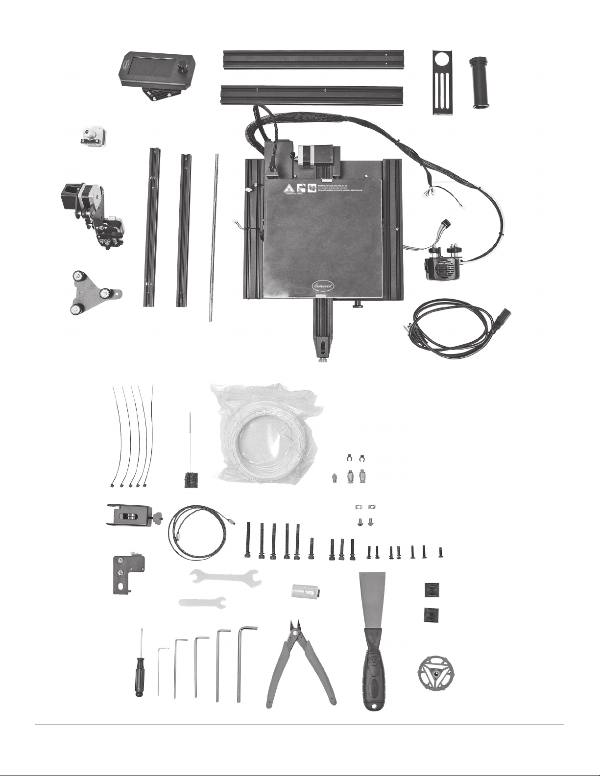
The EASTWOOD GENESIS FDM 3D PRINTER was designed to be the perfect option for 3D printing beginners searching for a robust yet affordable unit. Features
such as the aluminum extrusion gantry, quick heating hot end, heated build plate, Bowden drive extruder, and carborundum coated glass build surface make it
easy to create high quality prints quickly and efficiently. A convenient 4.3" [110 mm] color LCD screen is easy to use and adjust. The printer has a generous
738 cu. in. [12094 cc] print volume area capable of supporting parts 8.66” x 8.66” x 9.84" [220 x 220 x 250mm] and building them in common filaments such
as PLA and PETG.
READ AND UNDERSTAND ALL INSTRUCTIONS AND PRECAUTIONS BEFORE PROCEEDING.
This unit can produce high heat which can cause severe burns.
STATEMENT OF LIMITED WARRANTY
The Eastwood Company (hereinafter “Eastwood”) warrants to the end user (purchaser) of all new Eastwood-branded tools and chemicals (collectively called the “products”) that each will be free of defects
in workmanship and material. This warranty is void if the equipment has been subjected to improper installation, improper care or abnormal operations.
WARRANTY PERIOD:
All warranty periods begin on the date of purchase from Eastwood. Warranty Periods are listed below, along with the products covered during those warranty periods:
3-Year Warranty on Material, Workmanship, and Defects:
• Eastwood MIG 135 Welder • Eastwood TIG 200 DC • Eastwood MIG 175 Welder • Eastwood TIG 200 AC/DC
• Eastwood MIG 250 Welder • Eastwood MP140i Welder • Eastwood TIG 200 Digital • Eastwood MP200i Welder
• Eastwood Versa-Cut 20 • Eastwood Elite MP250i Welder • Eastwood Versa-Cut 40 • Eastwood 90A Flux Core Welder
• Eastwood Versa-Cut 60 • Eastwood ARC 80 Stick Welder • Eastwood Rotisserie • Eastwood Contour SCT®
• Concours Pro HVLP Paint Gun
Items not covered under this warranty: Consumables, unless deemed defective, are not covered by the 3-year warranty. Abuse, neglect, and lack of maintenance is not covered under this warranty.
All other components are covered by the warranty and will be repaired or replaced at the discretion of Eastwood.
2-Year Warranty on Material, Workmanship and Defects:
• Eastwood Air QST-30/60 Scroll Compressor • Eastwood 80 Gal. 7.5 HP Compressor • Eastwood 80 Gal. 5 HP Compressor • Eastwood 60 Gal. 4.7 HP Compressor
• Eastwood 60 Gal. 3.7 HP Compressor • Eastwood Panoramic Welding Helmet • Eastwood 30 Gal. 1.9 HP Compressor • Eastwood XL View Welding Helmet
• Eastwood Lg View Welding Helmet • Eastwood Auto Darkening Helmet • Concours 2 HVLP Paint Gun
Items not covered under this warranty: Consumables, unless deemed defective, are not covered by the 2-year warranty. Abuse, neglect, and lack of maintenance is not covered under this warranty.
1-Year Warranty on Material, Workmanship and Defects:
• Eastwood Tools Not Included Above • Fairmount Tools
Items not covered under this warranty: Consumables, unless deemed defective, are not covered by the 1-year warranty. Abuse, neglect, and lack of maintenance is not covered under this warranty.
90-Day Warranty on Material, Workmanship and Defects:
• Eastwood Paints & Chemicals • Rockwood Tools
Items not covered under this warranty: Consumables, unless deemed defective, are not covered by the 90-day warranty. Abuse, neglect, and lack of maintenance is not covered under this warranty.
Lifetime Warranty on Material, Workmanship and Defects:
• Selected Eastwood Hand Tools carry a Limited Lifetime Warranty
Items not covered under this warranty: Abuse, neglect, and lack of maintenance is not covered under this warranty.
CONDITIONS TO OBTAIN WARRANTY COVERAGE:
• Proof of purchase must be provided for all warranty claims
• Purchaser must first contact Eastwood at 1-800-343-9353 for an RMA Number before Eastwood will accept any warranty returns. Final determination of warranty on welding and cutting equipment
will be made by Eastwood.
WARRANTY REPAIR: If Eastwood confirms the existence of a defect covered under this warranty plan, Eastwood will determine whether repair or replacement is the most suitable option to rectify the
defect. At Eastwood’s request, the purchaser must return, to Eastwood, any products claimed defective under Eastwood’s warranty.
FREIGHT COSTS: The purchaser is responsible for shipment to and from Eastwood.
WARRANTY LIMITATIONS:
EASTWOOD WILL NOT ACCEPT RESPONSIBILITY OR LIABILITY FOR REPAIRS UNLESS MADE BY EASTWOOD. EASTWOOD’S LIABILITY UNDER THIS WARRANTY SHALL NOT EXCEED THE COST OF
CORRECTING THE DEFECT OF THE EASTWOOD PRODUCT. EASTWOOD WILL NOT BE LIABLE FOR INCIDENTAL OR CONSEQUENTIAL DAMAGES (SUCH AS LOSS OF BUSINESS, ETC.) CAUSED BY
THE DEFECT OR THE TIME INVOLVED TO CORRECT THE DEFECT. THIS WRITTEN WARRANTY IS THE ONLY EXPRESS WARRANTY PROVIDED BY EASTWOOD WITH RESPECT TO ITS PRODUCTS.
WARRANTIES IMPLIED BY LAW SUCH AS THE WARRANTY OF MERCHANTABILITY ARE LIMITED TO THE DURATION OF THIS LIMITED WARRANTY FOR THE EQUIPMENT INVOLVED. THIS WARRANTY
GIVES THE PURCHASER SPECIFIC LEGAL RIGHTS. THE PURCHASER MAY ALSO HAVE OTHER RIGHTS WHICH VARY FROM STATE TO STATE.

To order parts and supplies: 800.343.9353 >> eastwood.com 3
SPECIFICATIONS
Power Requirements: 100-120VAC, 50/60Hz, 1 Ph, 4.0A
200-240VAC, 50/60Hz, 1 Ph, 2.1A
Print Volume: 8.66”[220mm] X-Axis
8.66” [220mm] Y-Axis
9.84” [250mm] Z-Axis
738 cu in [12.1 Liters]
Extruder Temperature: 0°C - 240°C
Extruder: Bowden Drive
PTFE Tube Hot End
0.4mm Brass Nozzle
Print Bed Construction: Glass, Carborundum top coating
Print Bed Temperature: 0°C - 110°C
Print Bed Levelling: Manual
Controls: LCD Display, 480 x 272 Pixel Resolution
Storage Input: Micro SD Card
Filament Diameter: 1.75mm
Additional Features: Resume printing after power loss
Assembled Dimensions: 18.70” x 18.50” x 24.41” [475mm x 470mm x 620mm]
Display Screen Size: 4.3” [110mm]
TABLE OF CONTENTS
SPECIFICATIONS ........................................3
INCLUDES..............................................4
SAFETY INFORMATION ...................................6
GENESIS FDM 3D PRINTER COMPONENT IDENTIFICATION .......7
3D PRINTING GLOSSARY OF TERMS .........................8
GENESIS FDM 3D PRINTER SETUP
ASSEMBLY ........................................9
PLACEMENT .......................................15
POWERING ON......................................15
OPERATION OF THE GENESIS FDM 3D PRINTER ................16
MAIN SCREEN MENUS ....................................16
PRINT ............................................16
PREPARE..........................................17
SETTING ..........................................18
INFO .............................................18
PRINT IN PROGRESS SCREEN MENUS ...................19
PREPARING TO PRINT
SETTING Z-AXIS LIMIT SWITCH HEIGHT .................20
LEVELING THE PRINT BED ............................20
LOADING FILAMENT .................................21
UNLOADING FILAMENT...............................21
ADJUSTING FILAMENT TENSION . . . . . . . . . . . . . . . . . . . . . . . 21
USAGE OF THE EASTWOOD GENESIS FDM 3D PRINTER
SETTING UP ULTIMAKER CURA FOR USAGE WITH THE
EASTWOOD GENESIS FDM 3D PRINTER..................22
CREATING A G-CODE FILE ............................23
UTILIZING THE MICRO SD CARD AND USB ADAPTER .......24
PRINTING A G-CODE FILE .............................24
REMOVING PARTS FROM THE BUILD PLATE ..............24
QUICK GUIDE ...........................................25
TROUBLESHOOTING ......................................26
LEARN HOW TO SET UP
AND USE YOUR 3D PRINTER
with FREE Instructional Videos
Available at eastwood.com –
keyword search “3D Printer”

INCLUDES
COMPONENTS; FIG A
(1) Eastwood Genesis FDM 3D Printer Base Assembly
(Power Adapter, Control Boards, Build Plate, Y-Axis, Hot End, Wiring Harness) [A]
(1) Z-Axis Stepper Motor Assembly [B]
(1) Z-Axis Threaded Rod [C]
(1) Extruder/X-Axis Stepper Motor Assembly [D]
(1) Z-Axis Roller [E]
(1) Z-Axis Left Upright [F]
(1) Z-Axis Right Upright [G]
(1) X-Axis Beam [H]
(1) Z-Axis Upright Brace [J]
(1) Filament Holder Upright [K]
(1) Filament Spool Rod w/ Nut [M]
(1) 4.5ft (1.4m) Power Cord [N]
(1) Control Panel Assembly
(Control Panel, Bracket w/ Screws and T-Nuts) [P]
COMPONENTS; FIG B
(1) Putty Knife [Q]
(1) Straight Cutters [R]
(1) Extruder Manual Drive Wheel [S]
(1) Nozzle Clearing Rod [T]
(1) X-Axis Belt Tensioner [U]
(1) X-Axis Belt [V]
(1) Spare Nozzle [W]
(2) PTFE Tube Fitting [X]
(2) Tube Fitting Lock Clip [Y]
(5) M5x45 Hex Cap Screw w/ retained Lock Washer [Z]
(5) M5x25 Hex Cap Screw w/ retained Lock Washer [AA]
(5) M4x16 Button Cap Screw w/ retained Lock Washer [BB]
(2) M4x18 Flat Head Screw [CC]
(1) M4x14 Flat Head Screw [DD]
(2) M5x8 Button Cap Screw [EE]
(2) M5 T-Nut [FF]
(5) Zip Ties [GG]
(1) Micro SD to USB Adapter with 8GB Micro SD Card [HH]
(1) Z-Axis Limit Switch with Hardware Installed [JJ]
(2) Extrusion End Cap [KK]
(1) 200g PLA Filament [MM]
(1) Flat Blade Screwdriver [NN]
(1) 6mm Flat Wrench [PP]
(1) 10mm/8mm Double Ended Flat Wrench [QQ]
(1 each) 1.5mm, 2mm, 2.5mm, 3mm, 4mm Hex Key [RR]
4Eastwood Technical Assistance: 800.343.9353 >> tech@eastwood.com

To order parts and supplies: 800.343.9353 >> eastwood.com 5
A
FIG. AFIG. A
FIG. BFIG. B
B
C
D
E
F
G
H J
KM
N
Q
V
Z
AA BB CC DD
EE
FF
GG
HH
JJ
KK
MM
NN
PP
QQ
RR
P
RS
T
U
W X
Y

6Eastwood Technical Assistance: 800.343.9353 >> tech@eastwood.com
READ INSTRUCTIONS
• Thoroughly read and understand these product instructions before using the Eastwood Genesis FDM 3D Printer.
• Keep these product instructions for future reference.
BURN HAZARD!
• Contact with the Eastwood Genesis FDM 3D Printer Nozzle, Bed or attachments can cause serious burns.
• This printer generates high heat in the Extruder, Nozzle and Bed area which can exceed 465°F [240°C]. Use extreme caution when
adjusting and printing. Never touch Extruder, Nozzle, Bed and finished printed parts when switch is on. Allow sufficient time for cooling
before touching finished printed parts. Wear protective heat-resistant gloves when using this equipment.
RESPIRATORY HAZARD!
• Melted plastic printer filament can release hazardous or toxic substances. Breathing these fumes can cause serious respiratory health
conditions. Use in a well-ventilated area and always use NIOSH approved respiratory protection while using this Eastwood Genesis
FDM 3D Printer.
EYE INJURY HAZARD!
• Hot plastic may be ejected printing process. Eye protection should be worn at all times when operating this tool. Use ANSI approved
safety glasses. Everyday eyeglasses are NOT safety glasses.
INJURY HAZARD!
• DO NOT use finished printed objects to support the weight of a person or valuable property as serious injury or property damage may
occur. Finished objects are for hobby use only. DO NOT use objects produced by this printer to replace professionally designed and
manufactured, stress bearing parts in any device or vehicle.
DANGER indicates a hazardous situation which, if not avoided, will result in death or serious injury.
WARNING indicates a hazardous situation which, if not avoided, could result in death or serious injury.
CAUTION indicates a hazardous situation which, if not avoided, could result in minor or moderate injury.
NOTICE is used to address practices not related to personal injury.
SAFETY INFORMATION
The following explanations are displayed in this manual, on the labeling, and on all other information provided with this product:

To order parts and supplies: 800.343.9353 >> eastwood.com 7
EASTWOOD GENESIS
FDM 3D PRINTER
COMPONENT IDENTIFICATION;
FIG 1
[a] Filament Spool Holder
[b] Extruder Drive Assembly
[c] Hot End Assembly
[d] Nozzle
[e] X-Axis Belt Tension Adjuster
[f] Print Bed
[g] Print Bed Leveling Adjustment Wheels
[h] Y-Axis Belt Tension Adjuster
[j] Micro SD Card Port
[k] Micro USB Port
[l] Storage Tray
[m] LCD Screen and Control Knob
a
b
c
d
e
f
g
h
l
m
X-AxisX-Axis
Z-AxisZ-Axis
Y-AxisY-Axis
✓
✓
✓
✓
✓
✓
✓
✓
✓
✓
✓
✓
✓
✓
✓
✓
✓
gg
✓
gg
FIG. 1FIG. 1
✓
✓
✓
jjkk

8Eastwood Technical Assistance: 800.343.9353 >> tech@eastwood.com
3D PRINTING GLOSSARY OF TERMS
TERM DEFINITION
Hot End The hot end is the component group on the printer that generates heat to melt the filament for extrusion through the nozzle. This term
encompasses components such as the nozzle, heat sink, cooling fans, heat break, heater cartridge, and thermistor. The Eastwood Genesis
FDM 3D printer has a hot end with a PTFE tube heat break because it has excellent function below 240°C. The term “all metal hot end” is
often referenced for printing higher temperature materials, which means the filament only comes into contact with metals in its path through
the hot end.
Stepper Motor This is a type of motor commonly used on CNC machines. It has discrete phase positions, known as steps, that translate into accurate and fully
controlled movement. All axes on the Eastwood Genesis FDM 3D printer are controlled by a stepper motor.
CNC An acronym for computer numerical control, this means that a machine is primarily controlled by a computer. 3D printers fall into this category.
CAM Computer-aided machining, a software that takes a drawing file and turns it into a path that can be post processed into a G-code file for CNC
machine usage is referred to as CAM software. For 3D printing a Slicer is a type of CAM software.
G-code The programming code language that CNC machines understand. Typically, movement commands start with a “G”, hence the name G-code.
Miscellaneous commands start with “M”.
Nozzle The nozzle is the functional component that is heated so the filament can be forced through it. The nozzles are commonly brass or another
metal and have a nominal orifice in the end for the filament to be pushed through. The Eastwood Genesis FDM 3D Printer nozzle has a
standard 0.4mm orifice.
Post Processor The post processor takes a path created in a computer-aided machining software and converts it into the G-code file machine language.
Slicers do this all-in-one operation.
Slicer This is a type of CAM software specifically created for 3D printing. Slicers take a 3D object file, commonly an STL, and “slice” it into many
layers. It will automatically create a path for the nozzle to apply filament in and can post process that path into G-code so it can be saved and
run by the machine. Ultimaker Cura is the most popular slicer software and the one that Eastwood recommends.
Extruder The component group that forces the filament through the feed tube and extrudes it out the hot nozzle is called the extruder. Extruders usually
consist of a stepper motor, tubes/guides for the filament, a gear to bite into the filament, and a roller with spring tensioning system to drive the
filament into the gear. The Eastwood Genesis FDM 3D printer has what is called a Bowden drive extruder, meaning the motor for extrusion is
not integrated into the hot end. It is instead pushed through the guide tube into the hot end. Direct drive extruder systems have the motor and
tensioning system mounted to the hot end.
FDM Acronym for fused deposition modeling, also known as fused filament fabrication (FFF). Currently the most popular and affordable type of 3D
printer. The FDM process uses heat in the nozzle to melt filament and pressure to extrude it out the nozzle bonding it to the print bed, and then
itself as it builds up.
PLA Filament type, abbreviation for polylactic acid. PLA is popular in 3D printing due to ease of printing and low odor. Excellent filament for begin-
ners or making prototype parts. Not a good filament for withstanding temperatures greater than approximately 120°F for sustained periods of
time. Fairly stiff and high strength.
Filament In 3D printing the filament is the plastic type that is being used to build the part. Filament types include PLA, PETG, ABS, among many others.
They come in different sizes, weights, and colors coiled on a plastic spool. The filament spool size used with most 3D printers is of 1kg net
weight in an informally standardized size. The Eastwood Genesis FDM 3D printer requires the most common 1.75mm filament.
PETG Acronym for polyethylene terephthalate glycol-modified, another common filament type. Similar to PLA in regard to ease of printing but
withstands slightly higher temperatures. Much more flexible than PLA and offers some chemical resistance.
Print Bed The print bed, also known as build surface, print surface, build sheet, among others, is the surface to which the filament is printed on top of.
Almost all 3D printers today have a heated print bed, and there are many different surface types which have varying costs, surface finishes,
and adhesion levels. The print bed on the Eastwood Genesis FDM 3D printer is glass with a carborundum top coating. This is a light adhesion
surface and provides a smooth surface for the bottom of the print. The glass sheet can also be flipped if the preference is to print on
uncoated glass.

To order parts and supplies: 800.343.9353 >> eastwood.com 9
FIG. 2FIG. 2
FIG. 3FIG. 3
FIG. 5FIG. 5
EASTWOOD GENESIS FDM 3D PRINTER SETUP
The Eastwood Genesis FDM 3D Printer requires some basic component assembly before
operation. Unbox and layout all components, then begin assembly instructions.
ASSEMBLY
• First verify that all components are present as listed previously under INCLUDES.
• Start with the Eastwood Genesis FDM 3D Printer Base Assembly [A] and check
the pre-installed sets of four screws on the bottom, right, and left (hidden from
view) sides (FIG 2) of the aluminum extrusion base for tightness. Loose screws
can result in layer shift during prints.
• Adjust the Y-Axis eccentric tensioning nuts under the print bed (FIG 3) with the
10mm/8mm Double Ended Flat Wrench [QQ]. Adjust the tension on each just
tight enough so there is no looseness felt on the bed mount. Pushing the bed
should require light pressure and be smooth.
• Now ready the Z-Axis Left Upright [F], Z-Axis Right Upright [G] and four M5x45
Hex Cap Screws [Z]. Flip the Base Assembly up on its side for easy access to
the bottom (FIG 4a). Insert the screws through the bottom and thread them into
the aluminum extrusions of the Z-Axis Left and Right Uprights until they are fully
fastened, but can slide for adjustment later. The stepper motor mounting holes on
the Left Upright must be oriented as shown in (FIG 4b) with the holes near the
base of the machine. The orientation of the Right Upright is not critical because
the mount holes are unused.
• Slide the Extruder/X-Axis Stepper Motor Assembly [D] over the Left Upright and
the Z-Axis Roller [E] over the Right Upright (FIG 5). As with the Y-Axis tensioning
nut adjustment described above, adjust the eccentric tensioning nut on each tight
enough so there is no slop felt, but they still traverse smoothly. Remove each
from the Uprights and proceed to the following Extruder Assembly.
The threads in the aluminum extrusion are far weaker than the
steel screws and will strip if over tightened. Only hand snug all
fasteners with the hex keys [RR].
Eccentric
Nuts
Eccentric Nuts
✓
✓
✓
✓
✓
Bottom
Right
Left
(hidden from view)
FIG. 4FIG. 4aa
Stepper Motor
mounting holes
✓
FIG. 4FIG. 4bb

10 Eastwood Technical Assistance: 800.343.9353 >> tech@eastwood.com
FIG. 6FIG. 6
FIG. 7FIG. 7
FIG. 10FIG. 10 FIG. 11FIG. 11
• Start assembly of the X-Axis and Extruder Assembly with the X-Axis Beam
[H], Extruder/X-Axis Stepper Motor Assembly [D], and two M4x16 Button Cap
Screws [BB]. Place the X-Axis Beam with the counterbored side capturing the
roller wheel nut on the Extruder/X-Axis Stepper Motor Assembly plate (FIG 6),
and thread in the screws from the rear, through the plate, and into the aluminum
extrusion. While tightening, make the edge of the plate flush and parallel with the
top of the aluminum extrusion (FIG 7).
• Install the X-Axis Belt [V] in the channel and loop it around the stepper motor
drive gear to the bottom side. Pull it halfway down the bottom side (FIG 8).
• Roll the hot end assembly onto the X-Axis Beam with the hot end towards the
front side (FIG 9). Adjust the eccentric tensioning nut (FIG 10) just tight enough
so there is no slop felt, but it still traverses smoothly.
• Install the left end of the belt in the left slot on the bottom of the hot end
assembly (FIG 10).
• Place the Z-Axis Roller [E] with the counterbored side of the X-Axis Beam
capturing the button cap screw on the Extruder/X-Axis Stepper Motor Assembly
plate (FIG 6), and thread one M4x16 Button Cap Screw [BB] from the rear,
through the inner most hole, and into the aluminum extrusion (FIG 11).
FIG. 8FIG. 8 FIG. 9FIG. 9
Counterbore
Parallel
and flush
Eccentric Nut Install
✓
✓
✓
✓
✓
✓
✓
✓
✓
✓
✓
✓
✓
✓
✓
✓

To order parts and supplies: 800.343.9353 >> eastwood.com 11
The tensioner cover is plastic and will crack if over tightened.
Only hand snug all fasteners with the hex keys [RR].
• Remove the adjustment wheel from the X-Axis Belt Tensioner [U], and make
sure to reassemble in the same orientation it came apart (FIG 12). Loop the belt
around the wheel of the tensioner and install the end of the belt in the other slot
on the bottom of the hot end assembly (FIG 13).
• Install the tensioner cover over the wheel and thread the adjustment wheel on to
hold everything in place (FIG 14).
• Now the thread another M4x16 Button Cap Screw [BB] from the rear into the
remaining hole, through the plate, into the aluminum extrusion. While tightening
make the edge of the plate flush and parallel with the top of the aluminum
extrusion (FIG 15).
• Install the M4x14 Flat Head Screw [DD] into the front side of the tensioner cover.
Tighten the tension adjustment wheel until the belt has a slight tension (FIG 15).
Verify the pre-installed Y-Axis belt tension is similar.
FIG. 12FIG. 12
FIG. 13FIG. 13
FIG. 15FIG. 15
FIG. 14FIG. 14
DO NOT over tighten the belt, it will stretch out prematurely.
Tightness is not critical. The belt only needs be tight enough to
not skip a tooth when traversing rapidly.
Slot
Front
Top
✓
Parallel
and flush

12 Eastwood Technical Assistance: 800.343.9353 >> tech@eastwood.com
• The X-Axis and Extruder Assembly can now be rolled onto the Uprights. Gently
lower it down to the print bed. Do not allow it drop. (FIG 16).
• Install the Z-Axis Upright Brace [J] using four M5x25 Hex Cap Screws [AA].
Leave the screws loose enough so it can still slide. Place the two Extrusion End
Cap [KK] over the sharp exposed aluminum ends (FIG 17).
• With the X-Axis gantry resting on the bed, tighten down the two screws for each
upright so they are snug.
• Next, lift the X-Axis gantry up to the top of its range (FIG 18) and tighten the four
screws for the Z-Axis Upright Brace. The X-Axis gantry should move up and down
perfectly smooth now.
• Install the Z-Axis Stepper Motor Assembly [B] to the rear of the Left Upright with
the two M4x18 Flat Head Screws [CC]. Leave the screws slightly loose. Loosen
the preinstalled screws, and check that the top collar screw is loose (FIG 19).
FIG. 16FIG. 16
FIG. 17FIG. 17
FIG. 19FIG. 19
FIG. 18FIG. 18
✓
The threads in the aluminum extrusion are far weaker than the
steel screws and will strip if over tightened. Only hand snug all
fasteners with the hex keys [RR].
LoosenLoosen
ParallelParallel
and flushand flush
Tighten FirstTighten First
Tighten SecondTighten Second
✓
✓
✓
✓

To order parts and supplies: 800.343.9353 >> eastwood.com 13
Top
FIG. 20FIG. 20
• Thread the Z-Axis Threaded Rod [C] into the brass bushing from the top (FIG
20) of the Z-Axis Stepper Motor Assembly down fully until it is bottomed out in
the collar. Hold the motor flush on bottom and to the upright. Now tighten the M4
screws [CC] that go into the aluminum extrusion, then the pre-installed screws
that go into the motor (FIG 19).
TECH TIP: Look for gaps between the extrusions and the motor, then gently try to spin
the threaded rod back out of the collar. It should be effortless to spin when aligned, but
if binding is occurring, loosen up the motor mounting screws again and utilize thin shims
to achieve perfect alignment. For reference: the pictured unit required an approximately
0.035” thick shim (FIG 21).
• Once aligned, snug the collar so the rod rotates with the motor. The threaded rod
should be completely parallel with the upright throughout the range of motion.
• The 6-Pin Extruder Motor connector tagged E, 6-Pin X-Axis Motor connector
tagged X, and 3-Pin X-Axis limit switch tagged X can all be connected (FIG 22).
• Install the PTFE Tube Fitting [X] to the extruder. Insert the PTFE tube and use the
Tube Fitting Lock Clip [Y] to retain it (FIG 23).
• Install the Filament Holder Upright [K] with the two M5x8 Button Cap Screws
[EE] and M5 T-Nuts [FF]. Install the Filament Spool Rod [M] with the prein-
stalled nut (FIG 24).
FIG. 23FIG. 23
FIG. 21FIG. 21 FIG. 22FIG. 22
FIG. 24FIG. 24
ShimsShims
✓
✓
✓
✓

14 Eastwood Technical Assistance: 800.343.9353 >> tech@eastwood.com
• Install the Z-Axis Limit Switch [JJ] to the left upright using the preinstalled
T-nuts and screws. The switch should be towards the front side of the printer.
Plug in the 3-pin connector, from the base assembly, tagged Z (FIG 25).
Also plug in the 6-pin connector for the Z-Axis stepper motor, from the base
assembly, tagged Z.
• Unmount the Control Panel [P] from the mount by sliding it upward (FIG 26) and
use the preinstalled hardware to install the mount on the right-side aluminum
extrusion base. Reinstall the screen and plug in the ribbon cable (FIG 27).
• Utilize Zip Ties [GG] to secure wiring and ensure it won’t be caught up in a print,
on the machine, or on surroundings (FIG 28).
FIG. 27FIG. 27
FIG. 25FIG. 25
FIG. 26FIG. 26
FIG. 28FIG. 28
✓
✓

To order parts and supplies: 800.343.9353 >> eastwood.com 15
FIG. 29FIG. 29
FIG. 30FIG. 30
PLACEMENT
• Locate the Eastwood Genesis FDM 3D printer in a secure area away from
children, pets, and adverse environmental factors.
• Place on a surface that is sturdy and will not rock or sway.
• Strong airflow in the direct vicinity of the printer can have an adverse effect
on printing performance. Place away from fans or air conditioning vents.
• Provide adequate space around the unit to allow the gantry to traverse
unimpeded.
• 3D printing filament material creates toxic fumes and odor as the plastic is
extruded out of the nozzle. 3D printing in an unventilated area can pose an
inhalation risk. It is recommended to utilize the printer in a large space away
from the regular living space, such as a garage or shop.
• The printer may suffer performance problems in excessive ambient temperatures.
Room temperature is ideal however, if required, printing can be done in 50° -
100°F [10° – 37.8°C] environments.
POWERING ON
• The Eastwood Genesis FDM 3D Printer requires NEMA 5-15R receptacle on a
100-120VAC household circuit with at least a 10A breaker.
• Verify the power supply is in 100-120VAC mode for North American household
circuits (FIG 29). If the printer is being used in a location, such as Europe, where
200-240VAC power is standard the switch can be flipped the other way.
• Plug the connector on the power cord [N] into the rear of the machine, then plug
the other end into a suitable receptacle.
• Move the rocker switch on the rear of the machine to the “UP” position to power
up. The screen will display a brief loading sequence before showing the main
screen (FIG 30).
✓
✓
240V 120V240V 120V
PowerPower
onon
✓
PowerPower
offoff
✓

16 Eastwood Technical Assistance: 800.343.9353 >> tech@eastwood.com
OPERATION OF THE EASTWOOD GENESIS
FDM 3D PRINTER
The Eastwood Genesis FDM 3D Printer is completely operated from the side mounted
LCD display, controlled by the knob below the screen. Rotating the knob clockwise and
counterclockwise will scroll through the menus and adjust settings. Pressing the control
knob will select the highlighted option.
The following steps describe the interface, and how to accomplish certain tasks before
explaining printing preparations. The printer is configured by the factory with baseline
settings. The most common settings a beginner may adjust are nozzle temperature,
bed temperature, and preheat profile settings.
MAIN SCREEN MENUS (FIG 31)
PRINT (FIG 32)
The print option allows immediate access to the storage device for selection of a
print file.
The included Micro SD card has preloaded G-Code files for a quick start to verify
function of the printer.
Once a print file is selected the printer will switch to print in progress mode,
this screen is covered in Print in Progress Screen Options.
At the bottom of the screen the nozzle temperature actual/set point, bed temperature
actual/set point, movement speed, extruder speed, fan speed, Z offset, and X/Y/Z
coordinate location of the nozzle will always be displayed. Note that the X/Y/Z
coordinates will flash zero until the axes have been zeroed with auto home.
FIG. 31FIG. 31
FIG. 32FIG. 32

To order parts and supplies: 800.343.9353 >> eastwood.com 17
PREPARE (FIG 33a)
The prepare screen is useful for axis control, typically for levelling, and preheat/
cooldown modes.
• Move: The Move function allows the user to control the position, in millimeters,
of the machine's axes.
To avoid exceeding machine limits, the machine will automatically run the Auto
Home procedure if it has not been zeroed. See FIG 33b for the following:
- Move X: Control the X-Axis position.
- Move Y: Control the Y-Axis position.
- Move Z: Control the Z-Axis position.
- Extruder: Control how far filament is extruded. For this to function the
nozzle must be set to an adequate temperature to extrude filament
(greater than 180°C)
• Disable Steppers: Turns off all stepper motors. Select this before trying to
manually move any stepper motors to avoid possible damage.
• Auto Home: Auto zeros all three axes by contacting the limit switches.
• Set Home Offsets: This command can be used to define the zero point as
somewhere other than when it hits the limit switches.
• Preheat Profile 1: Sets the nozzle and bed temperatures to user defined
temperature set points. Useful for preparing to print to avoid waiting for the
printer to fully warm up when starting a print.
The following two menu items are not shown in FIG 33a.
Scroll down the menu to reveal them.
• Preheat Profile 2: Second set point profile, useful for another material with
slightly different temperature needs.
• Cooldown: Turns all temperature set points to zero (off) so the machine will
cool itself.
FIG. 33FIG. 33aa
FIG. 33FIG. 33bb

18 Eastwood Technical Assistance: 800.343.9353 >> tech@eastwood.com
SETTINGS (FIG 34)
The control menu has options for directly controlling temperatures, cooling fan speed,
preheat profile settings, motion control parameters, and firmware settings.
• Temperature: Manually sets the temperatures, cooling fan speed, and preheat
profile settings.
- Nozzle Temp: Control nozzle temperature set point in degrees Celsius.
- Bed Temp: Control bed temperature set point in degrees Celsius.
- Fan Speed: Control the part cooling fan speed, the relative adjustment
0 - 255 corresponds to 0 - 100% fan speed.
- Profile 1 Settings: Control and save all parameters for this preheat profile.
• Nozzle Temp
• Bed Temp
• Fan Speed
• Store Settings
- Profile 2 Settings: Control and save all parameters for this preheat profile.
• Nozzle Temp
• Bed Temp
• Fan Speed
• Store Settings
• Motion: Parameters under this menu are for maximum limits and transmission
ratios.
• Store Settings: Stores the current machine settings to the installed
storage device.
• Load Settings: Loads the machine settings stored on the installed
storage device.
• Restore Defaults: Resets to factory defaults and wipes the stored profile
on the storage device, if installed.
INFO (FIG 35)
Displays information about the printer size, firmware version, and contact details.
FIG. 34FIG. 34
DO NOT change unless directed to by Eastwood Technical
Personnel.
FIG. 35FIG. 35

To order parts and supplies: 800.343.9353 >> eastwood.com 19
PRINT IN PROGRESS SCREEN MENUS (FIG 36)
When a print is in progress the screen shows more information and options relevant
to the print. Upon finishing it will show the time to it took to print and ask to confirm
before returning to the main screen. Printing time elapsed and remaining time format
is displayed in (hh:mm) format.
• Tune
- Speed: Adjusting print speed scales the speed at which the printer
is operating, on-the-fly; eg.100 is the set speed as defined by the G-code,
120 is 20% faster, 90 is 10% slower.
- Nozzle Temp: Control nozzle temperature set point in degrees Celsius.
- Bed Temp: Control bed temperature set point in degrees Celsius.
- Fan Speed: Control the part cooling fan speed, relative adjustment 0 - 255.
- Probe Z-Offset: The Z-Offset is a very useful option for the start of the first
layer. It allows you to adjust the Z-Axis height above or below the
Auto home height in millimeters.
For example; If the first layer is not sticking to the print bed, the Z-Offset can be ad-
justed to a negative value like -0.20mm, on-the-fly, to get the perfect first layer height.
It can also be used to bump the height up if another surface, like tape, is added on top
of the build plate for better adhesion. After the auto homing is completed, this can be
adjusted, on-the-fly, to get the perfect first layer on a print.
• Pause: Pauses the print at the current location and turns off the heating.
The print can later be resumed.
• Stop: Cancels the current print in progress.
This option will ask for confirmation before cancelling the print.
FIG. 36FIG. 36

20 Eastwood Technical Assistance: 800.343.9353 >> tech@eastwood.com
PREPARING TO PRINT
SETTING Z-AXIS LIMIT SWITCH HEIGHT
It may be necessary to fine-tune the height of the Z-Axis Limit Switch to get the nozzle
to an appropriate height above the bed before levelling it.
• Start by adjusting the bed levelling screws down (FIG 37) in an even fashion.
Note that the minimum bed height is limited by the Y-Axis stepper motor. Allow
enough clearance for the bed to be pushed completely rearward without scraping
anything on the stepper motor. Having the springs under greater tension makes
for a more stable bed.
• Power on the printer and select Prepare > Auto home. This will return the
printer to the zero position.
• If the nozzle collides with the bed the limit switch must be adjusted up to provide
the nozzle sufficient clearance to fit a sheet of paper under it. Re-perform Auto
home to verify good clearance (FIG 37).
• If the nozzle is significantly higher than the print surface, adjust leveling screws.
If the travel limit of the screws will be exceeded, adjust the limit switch down and
re-level. Re-perform Auto home to verify good clearance.
• Once the Z-Axis Limit Switch is adequately adjusted make sure the fasteners are
tight enough that it will not shift.
LEVELING THE PRINT BED
An unleveled print bed will result in a poor first layer. Before using the printer, the
print bed must be levelled. Once the levelling has been complete, it does not need to
be changed unless a degradation in quality of the first layer is noticed, or something
has changed the level: e.g., changing a nozzle, removing the hot end, or moving the
print bed.
• One of the simplest methods to get a good bed level is utilizing a clean sheet
of printer paper as a feeler gauge. Auto home the printer and slide the piece of
paper underneath the nozzle.
• Slide the piece of paper back and forth, feeling for resistance, as that corner of
the bed is adjusted slowly upward with the leveling wheel. Once the paper starts
to contact the nozzle, stop adjusting (FIG 38).
• Next, in Prepare > Move, adjust the Z-Axis up approximately 1mm so that it
will not collide with the bed clip or surface as it traverses. Adjust the X-Axis to
220mm (maximum).
• Slide the piece of paper back under the nozzle and readjust the Z-Axis back to
0mm. Now repeat the same process of adjustment at this corner.
• Once finished, adjust the Z-Axis up at least 1mm and move the Y-Axis to 220mm
as well. Lower Z-Axis and repeat levelling process. Next, move to the final corner
0mm X-Axis, 220mm Y-Axis and repeat.
• Repeat the process rotating around and levelling every corner until the resistance
on the paper at each corner feels equal. This can take several rotations as fine-
tuning is done.
• The bed is now level and ready to print.
FIG. 37FIG. 37
FIG. 38FIG. 38
Table of contents