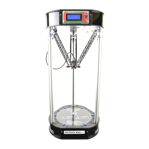
SeeMeCNC Rostock Max User manual

Rostock Max Assembly Guide
1
Welcome to the assembly guide for the Rostock Max 3D printer.
Before you begin, please make sure you’ve got the following tools and materials:
P1 & P2 Sized Phillips Screwdrivers
Standard Flat Head Screwdriver
3/32” Allen (hex) Wrench
5/32” Allen (hex) Wrench
Needle nose pliers
Forceps –these are VERY handy and will make your life easier in a number of the assembly
steps. They look like this:
You can purchase these online from Amazon for as little as $3.50 for a set of two.
I would recommend getting the ones with a slight curve to the jaws.
Wire Strippers
Wire Cutters
Metric Tape Measure or Meter Stick
A Small File –you may wish to get both a fine and coarse file. This is needed for adjusting
the spacing on some plastic parts later on in the build.
100-150 Grid Sand Paper

Rostock Max Assembly Guide
2
5/16” Wrench (used on the Cheapskate Bearings)
X-Acto Knife or other hand-held razor blade
PermaTex Ultra Copper High Temp RTV (used on the Hot End & Heated Bed)
Kapton Tape
Aluminum Foil
Crimp-On Wire Nuts
Split Flex Tubing (for the Hot End wires)
1 T-3/4 LED (Power on indicator for the Heated Bed)
1 1k 1/4 Watt resistor (for the LED above)
There will be a parts inventory included in the shipping box. Before you begin assembling your
Rostock Max, please check the parts included against this inventory. This will make sure you’ve got
everything you need to complete the assembly of your 3D printer. In the unlikely event that a part is
missing, contact SeeMeCNC immediately. Their technical support is excellent and you’ll have the
missing components on their way to you in no time.
The laser cut components in the Rostock Max kit are held in place with masking tape to ensure
that they’re not damaged in transit. The simplest way to remove these parts from the scrap material is
to use a razor blade to cut the tape around the perimeter of the part.
Each laser cut part also has a protective film on it that must be removed. This film prevents
“flash-over” from the laser cutting process from leaving scorch marks and combustion byproducts on
the parts. The film is removed easily –however, the film in the lettering can be difficult to remove. I
recommend using the edge of a credit card or stiff plastic scraper to remove the remaining film from
these areas.
Finally, take a dry washcloth or shop towel and wipe down the edges of each part. This will
remove most of the “soot” left over from the laser cutting process. If you’ve got an Acrylic kit, you can
of course skip this step.

Rostock Max Assembly Guide
3
Figure 1 –The parts for the Rostock MAX printer.

Rostock Max Assembly Guide
4
1 –Assembling the Machine Base
1.1 –Pop out the counter sink rings from the bottom plate (P/N: 68355)
Figure 2 –Countersink rings.
1.2 - The counter-sink rings are simply circles have been engraved through the Melamine
surface. Popping them out is easy using the point of a razor knife. It exposes the softer inner material
of the Melamine and allows flat head screws to create their own counter-sink by the pressure they apply
as they’re tightened down.
1.3 –Install the six feet to the bottom face of the base plate (P/N:69355).
Figure 3 –Plastic parts that make up the feet for the machine.

Rostock Max Assembly Guide
5
1.4 - In the photo below I’ve got the first two feet installed – note that I initially inserted the
nylon fasteners incorrectly. The nuts should be on the _other_ side. Installing them as shown in the
photo will prevent the soft rubber caps from fitting properly.
Figure 4 –First two feet mounted.
1.5 - This is what the six feet should look like when installed in their proper location:
Figure 5 –All six mounted, with rubber caps installed.
1.6 - The white caps just fit over the black plastic feet. Makes for a great non-slip assembly.

Rostock Max Assembly Guide
6
1.7 –Install the Tri-Supports (P/N: 86352), T-Slot Supports (P/N: 68377), and Motor Mount
(P/N: 68364)
Figure 6 - Tri Support and T-Slot Support
Figure 7 - Dry fitting the T-Slot and Tri-Support together.

Rostock Max Assembly Guide
7
1.8 - Dry fit the parts as shown in Fig 7 in order to get an idea how they go together. You’ll do
this for many steps in the assembly guide. Next, pop out the counter-sink rings on the Tri-Support and
install a pair of #6-32 Nylon lock nuts into the notches in the T-Slot Support as shown below.
Figure 8 - Lock nut installed in the T-Slot Support.
1.9 - Take two #6-32, 1” long flat head machine screws and attach the T-Slot Support to the Tri
Support as shown. Make sure that the counter-sink rings are facing out when you assemble the parts.
Figure 9 - Tri Support assembled.

Rostock Max Assembly Guide
8
1.10 - Install the Motor Mount on the T-Slot Support. You’ll want to insert two #6-32 Nylon lock
nuts as shown. Use a #6-32, 1” flat head machine screw to attach the Motor Mount to the T-Slot
Support. Do not tighten it down! Drive the screw in only a bit so it engages the Nylon. This will be
tightened down when the assembly is installed in the base plate.
1.11 - You may wish to install the stepper motors (Steps #4 & #5 below) and their connectors at
this point. It's easier to install the stepper motors on the X & Y axes without the doors in place. (The
connectors for the X and Y axis motors can be connected directly to the wires on the stepper motors,
but the Z axis requires a short extension to reach the electronics bay.)
Figure 10 - Motor Mount attached.
1.12 –Install Tri Support assemblies into the base plate. Before mounting in the base, install the
#6-32 nylon locknuts - doing them at this stage is much simpler than when the assembly is set in the
alignment notches in the base. Also note that the locknuts may not be the same dimension as the
notches they go into. They may be slightly over or under-sized depending on how they're measured.
The nuts will try to rotate and it makes the fit difficult. If the nut doesn't fit easily, turn it to a new set of
faces until it fits properly.

Rostock Max Assembly Guide
9
1.13 - Leave the screws a bit loose until all three assemblies are installed. Install first two as
shown:
Figure 11 - Two Supports installed.
1.14 - Install Power supply mount in third support –note that it’s a simple friction fit at this
point. It gets attached to the base when the whole assembly is installed.
Figure 12 - Power Supply Bracket in place.

Rostock Max Assembly Guide
10
1.15 - Place third assembly as shown
Figure 13 - Final Tri-Support installed in the base.
1.16 - Finally, tighten screws but leave them a little bit loose. Having the components
slightly free to move will help when you’re attaching the top to the base.
1.17 - Install Cover Brackets (P/N: 68361). The brackets that are installed to either side of
the power supply need to have threads cut in them.
Figure 14 - Cutting threads in the bracket.
1.18 - To cut the threads in the bracket, take a #10-32 socket head cap screw and carefully
thread them into the holes at the top & bottom of two brackets. This is where the Nylon thumb screws
will be installed in order to hold the plastic wrap-around cover.

Rostock Max Assembly Guide
11
1.19 - Using #6-32 Nylon lock nuts and #6-32, 1” flat head machine screws, install the
cover brackets in the base.
Figure 15 - Cover Brackets and Electronics Door installed.
1.20 –Install Electronics Mount (P/N: 68358) and Support Panel (P/N: 68357). Refer to Fig. 15
above for the location of the Electronics Panel. The door “pin” fits into the hole located next to
the X axis T-Slot mount.
1.21 - Install the Support Panel as shown –the door “pin” fits into the hole next to the Y axis T-
Slot mount.
Figure 16 - Support Door installation.

Rostock Max Assembly Guide
12
1.22 –Install the Base Top (P/N: 68351) With a razor knife, pop out all the counter-sink rings in
the Base Top. Ensure that you’ve got #6-32 Nylon lock nuts installed in the notches in the various
vertically oriented components. It’s difficult to install them all when the top is in place. Orient the top
so that the Z axis is straight across from the Electronics Panel
Figure 17 - Base Top Orientation
1.23 - It can be difficult to get all the tabs aligned with the slots in the top of the machine. I
recommend that you choose a point, get a few tabs inserted in the base slots and then loosely install a
few of the #6-32, 1” flat head screws around that location. This will allow you to work your way around
the top getting tabs locked in place without having them pop off areas you’ve already got set in place.

Rostock Max Assembly Guide
13
2 –Installation of the Heated Bed
2.1 - Identify the nine holes in the top marked with a laser engraved “1”. These holes are where
you’ll install nine #4-40 T-Nuts from below. The simplest way to seat the t-nuts is to use one of
the heated bed mounting screws and a washer to pull the t-nut into place. Place a t-nut into
one of the correct holes and thread in a #4-40 ¾” socket head cap screw with a washer on it.
Tighten it down until the tiny prongs have penetrated fully into the Melamine. If you’re building
an Acrylic version, flatten the prongs with your needle nosed pliers and tape the t-nuts in place
with a bit of scotch or other tape.
2.2 –Attach the heated bed to Mount Bed Insulator (P/N: 68335) using eight #4-4 ¾” socket
head screws. Set a small plastic spacer over each of the mounting holes that you installed a #4-
40 t-nut into. Set the heated bed & Bed Insulator in place. Make sure that the solder pads for
the heated bed are oriented towards the slot near the Z axis as shown in the below.
Figure 18 - Heated Bed Position

Rostock Max Assembly Guide
14
3 –Install Belt Pulleys on Stepper Motors
3.1 –When installing the pulley, make sure you do NOT over-tighten the screws. The belt pulley
is made from aluminum and can be stripped out easily. Tighten both screws equally.
Figure 19 - Belt Pulley Installed
3.2 - Note that if the set screws in your kit are as large as those shown in Fig. 19, you’ll need to
install the pulley after you’ve installed the stepper motor in the motor mount. The set screws won’t
clear the opening in the motor mount.

Rostock Max Assembly Guide
15
4 –Install the Connectors on the Stepper Motors
4.1 –If you’re installing the RAMBo or other controller board on the inside face of the
electronics mounting plate/door, you only need to add extension wires to the stepper motor for
the Z axis. If you’ll be installing the LCD controller, the drive electronics must be installed on the
inside of the electronics mounting plate. If the electronics are installed on the outside face of
the electronics mounting plate, you’ll need to test fit each stepper motor in order to determine
which ones will require an extension cable.
4.2 –Using the included wire, the extension wiring pattern goes like this:
Stepper Wire Extension Wire
Red----- ---------------------Red
Black------------------------Black
Green----------------------Green
Blue------------------------White
4.3 - The crimp on connector is wired in this order:
Pin 1 –Red
Pin 2 –Blue (White if using the extension)
Pin 3 –Green
Pin 4 –Black

Rostock Max Assembly Guide
16
4.4 - Pin 1 on the connector is indicated by a small triangle pointer that points to the end of the
connector. Fig. 20 below shows a 2 pin connector with this pin 1 arrow. The four pin stepper
connectors have the same style indicator.
Figure 20 - Pin #1 Indicating Arrow
Figure 21 - Stepper motor with connector installed

Rostock Max Assembly Guide
17
5 –Installing the Stepper Motors to the Motor Mounts
5.1 –The stepper motors are installed using four M3, 10mm pan head screws. I would
recommend using #4 star lock washers for extra peace of mind, but these are not included in the kit.
5.2 - Be very careful not to over-tighten the screws as you can easily strip out the holes on the
stepper motors.
5.3 - There are access holes directly across from each of the four stepper motor mounting holes
–they are there to allow you to install the screws on each motor. A longer than normal screwdriver may
help here.
5.4 - At this point you’ll want to install the belt pulley on each motor if you haven’t done so
already. Make sure that when you install the pulley, it’s positioned with the teeth aligned in the center
of the space as show in Fig. 22.
Figure 22 - Pulley correctly installed

Rostock Max Assembly Guide
18
6 –Installation of the Power Supply
6.1 –Install the power supply as shown in Fig. 23. The power supply is attached to the power
supply mount using four #6-32 ½” Nylon pan head screws. You’ll need your flat tip screwdriver for this.
Figure 23 - Power Supply Installation
6.2 - Insert the power supply with the wiring end pointing toward the center of the machine and
rotate to the left to set it into position.
6.3 - Do not tighten all four screws until you have them all started, otherwise you’ll only be able
to place three of the four. I recommend starting the two screws closest to the Tri Support that the
power supply mount mates to.

Rostock Max Assembly Guide
19
7 –Installation of the RAMBo Controller
7.1 –If you’re planning on installing the LCD control panel, you’ll want to install the RAMBo on
the inside of the electronics mounting plate.
7.2 - The installation uses four #4-40 x ¾” socket head cap screws, four #4-40 t-nuts, four #4 flat
washers and eight of the small plastic spacers.
7.3 - If you're building the Melamine version, don't fold back the prongs on the T-nuts. Instead,
take one of the mounting screws and a #4 washer and use that to set the T-nut into the mounting panel
as shown below:
Figure 24 - Installing the T-Nuts, front side
Figure 25 - Installing the T-nuts, back side

Rostock Max Assembly Guide
20
7.4 –If you’re installing on the inside of the mounting plate, orient the RAMBo such that the
stepper motor connectors are towards the bottom of the mounting plate. This allows the USB cable to
exit through the finger notch on the door.
7.5 - If you’re mounting to the outside, orient the board such that the stepper motor connectors
are close to the top of the mounting plate.
7.6 - The SeeMeCNC assembly video shows using one plastic spacer on either side of the board.
I chose to install the board with both spacers stacked behind the circuit board. Take care not to over-
tighten the screws or you could crack the circuit board.
Figure 26 - Mounting the RAMBo
Table of contents
Other SeeMeCNC 3D Printer manuals
SeeMeCNC
SeeMeCNC Artemis User manual
SeeMeCNC
SeeMeCNC orion delta User manual
SeeMeCNC
SeeMeCNC Rostock MAX v2 User manual
SeeMeCNC
SeeMeCNC DropLit User manual
SeeMeCNC
SeeMeCNC rostock max v2.0 User manual

SeeMeCNC
SeeMeCNC Delta User manual
SeeMeCNC
SeeMeCNC Rostock Max v3 User manual

SeeMeCNC
SeeMeCNC Rostock MAX v2 User manual
SeeMeCNC
SeeMeCNC Rostock MAX v2 User manual

SeeMeCNC
SeeMeCNC orion delta User manual


