Easy-Kleen Caribou Series User manual

!""!
#"$!%&"' ()*)+()++ ,,,&!%&"'

HIGH-PRESSURE WASH EQUIPMENT AND THE SPRAYS THAT THEY GENERATE CAN CAUSE
SERIOUS INJURY. THINK SAFETY FIRST!
The forces generated by high-pressure sprays can penetrate clothing or skin and cause severe personal
injury. Additionally, the high-pressure spray and material dislodged by it may be deected back toward
you and/or persons or objects nearby. Water or water combined with cleaning agents or soap can make
oors and other surfaces slippery, creating the possibility of persons or objects falling. Power cords and
high-pressure hoses create a further hazard and should always be stored neatly when not in use. During
any cleaning operation, hoses and power cords should be laid at on the ground and away from areas
where they may become entangled in objects or cause tripping of persons passing by. Always consider
the surrounding environment and conditions before beginning any cleaning operation.
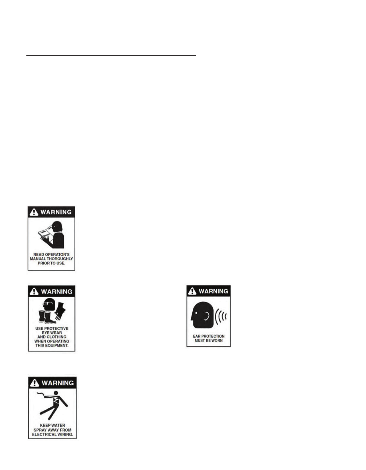
• Eye protection, safety footwear, and protective clothing should always be worn when using this equipment.
• Never place any part of your body in front of the high-pressure nozzle.
• Never direct the high-pressure spray at yourself or any other person.
• Never allow children to operate the pressure washer.
• Hold the trigger gun/wand assembly securely with both hands when operating the pressure washer.
• Never direct the high-pressure spray at any electrical device or the pressure washer itself.
• Never operate electrically powered pressure washers where they will be exposed to rain or other forms of
precipitation or spray.
• Never operate the pressure washer with damaged parts or components.
• Never allow the machine or accessories to freeze.
• Do not drive over or crush high-pressure hoses or allow them to come in contact with sharp objects.
• Do not operate electrically heated system without rst supplying water to the heat exchanger tank. Fill the
water tank with clean water to safe levels of operation.
• Do not attempt to move or pull the machine (portable equipment) by the high-pressure hose or
electrical cord.
• When not in use, turn the machine OFF and depress the trigger gun to remove residual system pressure.
• Do not operate the system without a water supply.
• Do not allow the machine to operate (by-pass) for extended periods with the trigger gun closed or without
discharging water.
• Avoid rapid triggering and releasing of the gun. Smooth triggering will extend the life expectancy of the
system components.
High-pressure wash system components are sensitive to solid matter and debris that may be present in
the uid moving through them. Additionally, material allowed to enter hoses and various connections
when the equipment is improperly moved or stored can increase the potential for failure. To avoid
component fouling, poor system performance, and costly downtime, always ensure that a clean water
supply and when possible, a clean environment is provided to the machine.

!
""
# $
%&
"
'!
This manual contains operational information that is specic for the Electrically Heated Industrial
Hot Water Fully Electric Models.
Read the following instructions carefully before attempting to assemble, install, operate, or service
this pressure washer. Failure to comply with these instructions could result in personal injury and/or
property damage.

WARNING: To reduce the risk of injury, read operating instructions carefully
before using.
1. Read the instructions in this manual carefully before attempting to assemble,
install, operate, or service this pressure washer. Failure to comply with the
instructions could result in personal injury and/or property damage.
2. Be thoroughly familiar with all controls and know how to stop the machine in the
event of an emergency.
WARNING: Use protective
eyewear and clothing when
operating equipment in
order to avoid personal
injuries.
WARNING: This
machine exceeds
85db. Appropriate
ear protection must
be worn.
WARNING: Keep water spray away from electrical wiring.
3. All electrically powered equipment must be grounded at all times to prevent
fatal electric shocks. Do not spray water on or near electrical components. Do
not touch electrical components while standing in water or when hands are wet.
Always make sure machine is disconnected from power source before servicing.
Ensure machine is plugged into a ground fault interrupter when in use.
Easy-Kleen’s rst priority is the safe operation of our high pressure cleaning equipment. This can be
achieved by following the operation and maintenance instructions as explained in this manual and all
other enclosed information.
This manual contains essential information regarding the safety hazards, operation, and
maintenance associated with this machine. The manual should always remain with the machine,
including if it is resold.
ALL CAUTIONS AND SAFETY WARNINGS MUST BE FOLLOWED TO AVOID PERSONAL INJURY AND/
OR DAMAGE TO EQUIPMENT.
THIS EQUIPMENT IS TO BE USED ONLY BY TRAINED OPERATORS AND MUST ALWAYS BE ATTENDED
TO DURING OPERATION.

WARNING: Trigger gun kicks back. Hold with both hands.
5. Hold on rmly to the gun and wand during start up and operation of the
machine. Do not attempt to make adjustments while the trigger gun is in
operation.
6. Make sure all quick coupler ttings are properly secured before operating
pressure washer.
WARNING: Risk of injury from falls when using ladder.
7. Do not overreach or stand on anything unstable. Keep good balance and make
sure to keep steady footing at all times.
WARNING: Protect from freezing.
8. It is important to keep your machine from freezing in order to keep it in its
best working condition. Failure to protect your machine from freezing may cause
damage to the machine and personal injuries may occur as a result.
WARNING: Risk of injection or severe injury to persons. Keep clear of
nozzle spray.
4. High pressure spray can cause serious injuries. Never point pressurized spray at
any person or animal. Handle the spray assembly with care.
WARNING: Risk of
injury. Hot surfaces
can cause burns.
WARNING: Hot
discharge uid.
Do not touch or direct
discharge stream
at persons.

WARNING: High Voltage.
9. For machines with an electric motor or 120V burner – THE MACHINE MUST BE
ELECTRICALLY GROUNDED. Must be connected to a GFCI (Ground Fault Circuit
Interrupter). All service must be done with the machine disconnected from the
supply circuit.
10. Protect high pressure hoses from sharp objects and vehicles. Inspect condition
of hoses prior to use, or serious injury could occur.
11. Do not pass acids or other caustic or abrasive uids through the pump.
12. Never run pump dry of water or let the pump run with the trigger gun released
for more than 2 minutes.
13. Do not attempt to operate this machine if fatigued or under the inuence of
alcohol, prescription medications, or drugs.
14. Some of the maintenance procedures involved in this machine require a certied
technician (these steps are indicated throughout this manual). Do not attempt to
perform these repairs if you are not qualied.
If you need further explanation of any of the information in this manual, suspend any activity
involving the equipment and call our toll free number for assistance at: 1-800-315-5533.

INDUSTRIAL HOT WATER FULLY ELECTRICALLY HEATED
MODEL GPM PSI HEATER
INPUT
MOTOR
HP
TOTAL AMP 3PH DIMENSIONS
L” x W” x H”
208 460 575
EH411E24A 4 1200 24 KW 5 72.5 33.3 26.6 32 x 28 x 52
EH411E48A 4 1200 48 KW 5 134.8 62.2 49.7 32 x 28 x 52
EH420E24A 4 2000 24 KW 5 77.1 35.5 28.4 32 x 28 x 52
EH420E448A 4 2000 48 KW 5 139.6 64.4 51.8 32 x 28 x 52
EH420E472A* 4 2000 72 KW 5 N/A 93.3 74.4 48 x 28 x 52
EH430E424A 4 3000 24 KW 7.5 85 39.1 31.3 32 x 28 x 52
EH430E448A 4 3000 48 KW 7.5 147.5 68 54.4 32 x 28 x 52
EH430E472A* 4 3000 72 KW 7.5 N/A 96.5 76.9 48 x 28 x 52
EH440E448A 4 4000 48 KW 10 154 70.9 56.7 32 x 28 x 52
EH440E472A* 4 4000 72 KW 10 N/A 99.8 79.9 48 x 28 x 52
EH450E448A 4 5000 48 KW 15 N/A 75.9 60.7 36 x 54 x 36
EH450E472A* 4 5000 72 KW 15 N/A 104.8 83.9 48 x 54 x 36
EH550E448A 5 5000 48 KW 20 N/A 82.8 66.5 36 x 54 x 36
EH550E472A* 5 5000 72 KW 20 N/A 112.2 89.8 48 x 54 x 36
EH535E448A 5 3500 48 KW 10 154 70.9 56.7 32 x 28 x 52
EH535E472A* 5 3500 72 KW 10 N/A 99.8 79.9 48 x 28 x 52
EH562E448A 5.6 2000 48 KW 7.5 147.5 68 54.4 32 x 28 x 52
EH562E472A* 5.6 2000 72 KW 7.5 N/A 96.9 77.6 48 x 28 x 52
EH612E448A 6 1200 48 KW 5 139.6 64.4 51.8 32 x 28 x 52
EH620E448A 6 2000 48 KW 10 147.5 68 54.4 32 x 28 x 52
EH620E472A* 6 2000 72 KW 10 N/A 96.9 77.6 48 x 28 x 52
EH812E2448A* 8 1200 48 KW 7.5 147.5 68 54.4 32 x 28 x 52
EH812E2472A* 8 1200 72 KW 7.5 N/A 96.9 77.6 48 x 28 x 52
EH820E2448A* 8 2000 48 KW 10 154 70.9 56.7 32 x 28 x 52
EH820E2472A* 8 2000 72 KW 10 N/A 99.8 79.9 48 x 28 x 52
EH830E2448A* 8 3000 48 KW 15 165 75.9 60.7 36 x 54 x 36
EH830E2472A* 8 3000 72 KW 15 N/A 104.8 83.9 48 x 54 x 36
EH1030E2472A* 10 3000 72 KW 20 N/A 112.2 89.8 48 x 54 x 36
EH1030E2496A* 10 3000 96 KW 20 N/A 141.3 113.1 48 x 54 x 36
EH1030E24115A* 10 3000 115 KW 20 N/A 164.3 131.4 48 x 54 x 36
* MODELS HAVE DOUBLE COILS

Thank you for selecting a quality Easy-Kleen product. We are pleased to have you included among the
many satised owners of Easy-Kleen machines. Years of engineering have gone into the development of
these ne products and only top quality components and materials are used throughout. Each machine
is carefully tested and inspected before leaving our plant to ensure years of dependable performance.
To continue to receive satisfactory performance, remember that this machine represents a substantial
investment on your part, and if properly cared for and maintained, it will return this investment
many times over. As with all mechanical equipment, your machine requires proper operation and
maintenance as outlined in this manual for maximum trouble free life.
This manual has been prepared under the direction of our engineering and service technicians.
Their experience in designing, manufacturing, installing, and servicing our equipment from our
company’s inception, is condensed in this manual. They know what information end users need in order
to get optimal performance from their pressure washer. Please read carefully.
This manual contains information that will be specic for your pressure washer as well as similar models.
Carefully review any additional manuals that have been included with your system and follow
ALL ADDITIONAL OPERATING INSTRUCTIONS AND SAFETY NOTICES. They are specic for the quality
components that have been used to manufacture your machine and are an integral part of operating
and maintenance procedures.
The management & sta at Easy-Kleen are proud of the equipment that we design and manufacture,
and we thank you for making us your # 1 choice in pressure washers. If you have any questions, please
do not hesitate to call us at: 1-800-315-5533.
Our goal is that you will be satised with the performance, quality, and service you receive from
Easy-Kleen and that if you need to replace this machine in years to come, you will give us the
opportunity to continue supplying your equipment.
PLEASE READ MANUALS CAREFULLY BEFORE USING THE MACHINE. EXAMINE THE MACHINE AND
CRATE CAREFULLY FOR SHIPPING DAMAGE OR MISSING PARTS. REPORT ANY SHORTAGES OR
DAMAGE CLAIMS TO FREIGHT CARRIER OR DEALER PROMPTLY.

The electrical single heater consists of a, single coil heat exchanger, control components, thermo probe,
oat switch, high pressure hoses, and connections.
THIS MACHINE SHOULD BE PROTECTED FROM FREEZING AT ALL TIMES. (SEE MAINTENANCE)
Place system in any suitable location. Adjust the leg bolts to level the unit. It is recommended to provide
ample room and support for installation, maintenance, and operation of elevated systems. Drainage
should be provided near the unit.
The pumping unit is designed to be located on top of the heat exchanger, although it may be located
beside it.
In every Electrically Heated System the following standard features can be found:
1. Automatic start circuit complete with manual override
2. Automatic time delay stop circuit
3. Automatic temperature controlled heat exchanger
4. Thermal safety shutdown on pumping system to protect pump components
5. Low water shutdown circuit to protect heating elements from lack
of water in the heat exchanger
6. Corrosion resistant incoloy heating elements (tube type)
7. 50’ of 3/8”steel braided hose
8. High pressure trigger gun
9. Lance complete with chemical valve
10. Chemical injection system
11. Complete motor fusing and overload protections
Note: Some of these features may not apply to your build. Check with serial and model number
for features that come with your pressure washer.

The function of our heat exchangers is to enhance an existing high pressure cold water wash system
by enabling it to create hot water downstream of the height pressure pump. It also allows the system
to operate automatically, virtually eliminating the problems that are often associated with “hands-on”
controls. High pressure cold water is circulated through a tubular coil which is submerged in hot water
in an unpressurized tank. The cold water is then heated by the surrounding hot water.
Motor controls, as well as other system controls and safety features, are provided with the heat
exchanger and are enclosed within the unit eliminating the need for separate pump control.
Our heat exchangers have been designed with the maximum eciency in mind. There is no need for
messy and potentially dangerous fuel storage nor venting. The unit may be located in any convenient
location. High pressure hot water is only the squeeze of a trigger away, and our heat exchangers deliver
it to you instantaneously; NO WARM UP PERIOD.
Inlet connection to the heat exchanger is made by connecting a high pressure discharge hose
(optional) from the discharge port of the high pressure pump unit to one of the ttings provided on top
of the heat exchanger. DO NOT EXCEED MAXIMUM SYSTEM PRESSURE.
Discharge connection is made from the tting opposite the inlet to the hose/gun/lance assembly, or to
plumbing for remote station(s) operation.
Automatic controls include water temperature control, low heat exchanger water level shut o, and
pump motor control circuit complete with time delay stop. Motor circuit fusing and overload protection
are also provided. In addition all heat exchanger control circuits have provisions for connecting a ow
switch and optional pump thermal protector.
The thermostat maintains tank water temperature at approximately 180 degrees F (82 degrees C). A
level switch in the tank will open if the water level should drop to a point where operation of the unit is
aected.
Electrical service for the system is run to the terminal block on the electrical panel labeled L1, L2, and
L3. A ground lug is also provided. This unit must be properly grounded to prevent electrical shock.
A fused disconnect is to be provided according to local codes. Refer to ID plate for voltage and total
connected load.
ALL ELECTRICAL WORK TO BE PERFORMED BY A QUALIFIED ELECTRICIAN.
WARNING: THIS CONTROLLER MUST BE PROVIDED WITH SUITABLE OVERLOAD AND
OVERCURRENT PROTECTION IN ACCORDANCE WITH THE CANADIAN ELECTRICAL CODE PART 1.
UNIT TO BE CONNECTED TO A (GFCI) OR TWIST LOCK PLUG OR PERMANENT CONNECTION.

The high pressure pump motor is to be connected to the motor contactor overload connections labeled
T4, T5, and T6. Be sure that the motor current (see FLA rating on motor plate) is within the current rating
of the motor overload, and that the overload is set to the proper current level. A ground lug is also
provided for the motor circuit. Electrical leads from a ow switch (optional) are to be connected to the
terminal strip labeled FLOW SWITCH CONNECT, at terminals 7 & 8. An optional thermo probe may be
connected at terminals 9 & 10. The purpose of this probe is to protect the high pressure pump from
overheating. A thermally activated switch within the probe will open when the pump temperature is
too high, stopping the unit. The system will start again only when the temperature has been lowered to
an appropriate temperature. On units that are not equipped with this feature, a jumper wire (installed at
the factory), must connect terminals 9 & 10 and it is suggested that another type of thermal protector
be used.
Install the Electrically Heated System in accordance with pumping package and heat exchanger
directions. See pump and heat exchanger directions. This equipment should be installed and serviced
by qualied personnel.
!"#
Do not turn power on until the heat exchanger is lled with water as severe damage may occur if water
is not above heater elements. To ll heat exchanger, remove 1 ¼” pipe plug from the elbow ll pipe
located on the heat exchanger. Insert water hose and ll. Heater tank will require approximately 70
gallons (265 litters) of water on initial ll. After a water level has reached the ll elbow, the power may
now be turned on. It will take 15 to 20 minutes for the heat exchanger to reach operating temperature.
WATER WILL EXIT THE FILL PIPE WHILE THE HEATER TEMPERATURE IS RISING. This is due to the
heat expansion of the cold water just added. This will stop after the heater has reached its operating
temperature. Replace and hand tighten the 1 ¼”ll pipe plug. After initial heating of the tank, leave the
main power on to the equipment. This will ensure hot cleaning solution is available instantly on pump
start up.
#
Turn the inlet water supply on after the pumping package has been installed. See pumping package
section for details.
CAUTION! BEFORE PUMPING PACKAGE IS STARTED FOR THE FIRST TIME, OR AFTER
MAINTENANCE HAS BEEN PERFORMED ON ANY SUPPLY OR DISCHARGE WATER LINES, ALL AIR
MUST BE PURGED FROM THE SYSTEM. FAILURE TO DO SO MAY RESULT IN SYSTEM DAMAGE.

CAUTION: Pressure cleaning gun must be HELD ONTO SECURELY when the pump is turned on as
serious personal injury may be inicted if spray wand is allowed to move freely. High pressure spray
can cause SERIOUS BODILY HARM - HANDLE WITH CARE - NEVER POINT SPRAY AT ANY PART OF
THE BODY. Proper protective equipment should be worn if corrosive chemicals are used. With pumping
unit turned o, pull the gun trigger to ensure that the water is running through the nozzle. Check the
supply line to ensure there are no kinks in the hose. Release the gun trigger. Place the operators switch,
located on the heat exchanger, in the “A” automatic position. You are now ready to clean.
This unit has been adjusted at the factory and preset at the designed specications. DO NOT
READJUST IN AN ATTEMPT TO INCREASE PUMP PRESSURE. This will only increase the regulation
pressure which will cause internal pump damage or motor overload.
DAILY
To ensure a problem-free system, simple visual checks can be performed. Check for leaks in inlet
supply, pumping system, pump to heater hose, gun(s), and high pressure hose. Check and rell
chemical concentrate. Check pump oil level/condition. Check nozzle condition. If badly worn or leaking
conditions are found, qualied personnel should repair or place components with new original or
equivalent manufacturers parts.
Check equipment for proper operation. Nozzle spray should be uniform in ow, angle, and pressure.
Clean if nozzle is plugged and replace if worn. If a heavy pulsation is the hose or spray is observed,
repair of the pumping system is required.
WEEKLY
After the rst week of operation, it is recommended that 1litre of motor oil be added to the heat
exchanger tank through the 1¼” ll pipe. This oil creates a vapor barrier and slows evaporation of water
in the tank.
Check heat exchanger water level. The level must be up to the ller pipe neck. Add water if necessary. If
cold water has been added, heating may cause the expanding water to escape through the ller plug.
This will stop after operating temperature has been reached.
MONTHLY
Check system for operation. Automatic start/stop, hot high pressure water, and smooth operation
should be noted. Check tank water level, rell if necessary. Should the tank ever be completely emptied,
450 g of peralm P must be added to the tank. This prevents corrosion.
Change oil in pump crankcase. Note the condition of the oil when drained. If found to be creamy, the
water seals in pump may have to removed and replaced. Follow the pump manual directions.

PROBLEM POSSIBLE CAUSES SOLUTIONS
Pulsation
Excessive pressure and/
or temperature of uid
being pumped.
- Check pressures and/or temperature. Reduce to acceptable
level. Reduce pressure.
Unloader/regulator set
too high of pressure.
Running pump dry.
- Reduce Pressure.
Faulty Pulsation
Dampener
- Do not run pump without water. Check pre-charge, if low,
re-charge it or install a new one.
FAILURE TO MAINTAIN YOUR PRESSURE WASHER/EQUIPMENT, INCLUDING REGULAR
MAINTENANCE OF PUMP AND SYSTEM COMPONENTS, WILL VOID MANUFACTURER’S
WARRANTY.

Regular inspection and maintenance of your system is the best defense against equipment
failure and costly downtime. Additionally, the high-pressure wash systems can create safety hazards.
Simple checks, performed by the operator of the equipment or maintenance personnel on a regular
basis, will help to ensure safe operation and that the system’s maximum performance and life cycle is
achieved. The guidelines below pertain to the basic system and components only.
Further consideration should be given to optional accessories when included.
DAILY MAINTENANCE SHOULD INCLUDE THE FOLLOWING:
• Check that all water supply and high pressure discharge hoses as well as all power cords do not
create an obstruction that may cause anyone to trip or fall.
• Check that all controls, switches, and disconnects are readily accessible and can be reached quickly
in case of emergency.
• Check inlet water supply valves and hoses for signs of leakage and correct where needed.
• Check inlet water supply hose for kinks or other forms of restriction that can interrupt
proper ow into the system.
• Check that all electrical cords and wires are properly secured/connected and do not pose a potential
hazard for electrocution. All electrical supply and motor connections must include a ground wire.
• Check that the area around the unit is clear and dry.
• Check that all moving parts such as belts, pulleys, motor fans, etc., are clear of debris that could
become entangled or otherwise come in contact with them.
• Check the pump oil site glass or dipstick for the correct oil level and signs of contaminants
(water or metallic particles).
• Untangle the high presser hose if needed.
• Check the hose for nicks, cuts, and abrasions that can lead to leaks.
• Check that the nozzle is clear of debris and operates correctly.
• Check for adequate water to the unit.
• Check that the chemical tank is full.
• Check that the chemical tube is clear and in the tank.
WEEKLY:
1. Check and clean inlet lters and screens.
2. Check and clean the chemical lter/screen.
3. Check for signs of water and/or oil leaking around the pump.

MONTHLY
1. Update your record of inspections, problems, or any potential problems.
2. Check for any oil leaks at the crankcase, crankshaft, or piston seals.
3. Check controls are working within specications.
QUARTERLY
1. Change the pump oil every 3 months or 500 hours of use, whichever occurs rst.
2. Check the inlet and discharge valve assemblies and O-rings should be checked or changed every
3 months.
!"#$%%!
1. Change the oil in the pump after the rst 50 hours and every 500 hours after the initial oil change.
Use SAE 30 W Non-Detergent for GP Pumps and Hydraulic 68 for EK Pumps.
2. Change all other components on the pump as needed.

&'(()
If the equipment will be used or stored in areas where it will be exposed to temperatures below 0°
Celsius (32° Fahrenheit) for any period of time, precautions must be taken to prevent damage due
to freezing. DRAINING THE SYSTEM DOES NOT OFFER ADEQUATE PROTECTION. Use of a high
quality plumbing antifreeze or automotive windshield washer antifreeze is recommended. Glycol based
antifreeze may be used, but be sure to follow the manufacturer’s directions for correct mixture and for
proper disposal after use. The following method may be used to protect the system when not in use.
1. Disconnect the power supply to the machine and turn o all control switches (turn o engine on gas
powered machines).
2. Turn o the water supply.
3. Relieve any trapped pressure in the system by squeezing the trigger gun but leave high pressure
hose(s) attached to the discharge.
4. Remove supply hose.
5. Fill a clean container of sucient size to supply the machine with enough antifreeze solution for
approximately two minutes operation (i.e. 8 gallons for a 4 GPM system).
6. Connect a short hose to the inlet of the system and submerge the open end in the antifreeze close to
the bottom of the container.
7. Restore power to the machine and turn control switch to MANUAL position (Start engine on gas
powered machines).
8. Open and hold trigger gun until antifreeze is discharged from nozzle. (Most antifreeze compounds
will foam slightly when discharged from system). Discharged antifreeze may be directed back into
container for reuse or proper disposal.
9. Close the trigger gun momentarily to force solution through by-pass loop.
10. Repeat steps 1, 3, and 4.
If desired, compressed air may be connected to the inlet connection of the system to force the
remaining antifreeze solution from the system; however, air pressure should be regulated to no more
than 80 PSI.

&*&
The design feature of our Heat Exchanger allows high pressure cold water to be heated in an
unpressurized tank. Cold water entering the heat exchanger passes through a coil submerged in heated
water. Electrical controls for the exchanger and pumping package are mounted on the outside of the
tank. The protective outer wrap and front panel enclose the controls.
After lling the water tank to the level indicated in Fig3, turn the heat exchanger switch to the “ON”
position. Once the heater has reached the set temperature, water may drip through a small hole in the
90 deg. elbow to prevent pressure from building up which can naturally occur when water is heated to
high temperature.
FIGURE 3
Heat Exchanger

8
48 KW HEAT EXCHANGER

(+,'
WARRANTY TIME LINE
Electric Motors 1 Phase 18 Months
3 Phase 24 Months
For warranty of these items, manufacturer needs to be contacted
Oil Burners Ignitors, Fuel Solenoid, Burner Motor, Fuel Assembly, Drive Shaft, Electrodes
Blower, Wheel Fuel Pump
1 Year for Parts
Propane
/Natural Gas Burners
Burner Rings, Gas Valves, Gas Valve Control Board 1 Year
Fitting All Fittings, Brass Stainless Steel, Steel, Etc. 30 Days
Heating Coils *Damage due to neglect, freezing or hardwater is not covered 5 years - limited
Gas Motors Must contact Honda/Kohler for Warranty
Lifan Motor Contact Easy-Kleen for Warranty 1 Year (for commercial use)
Frames *Paint is not covered under the manufacturer’s warranty due to aggressive
environment or natural wear.
7 Years
Plastic Tanks Water or Fuel 1 Year
Accessories
/Wear Items
Unloader, Regulating Valves, Safety Valves, Jetter Valves, Check Valves, Foot
Valves, Pulsation Dampeners, Trigger Guns, Rotary Nozzles, Chemical Injectors,
Hose (Jetter Hose Not Included), Hose Reels, Sandblast Kits, Surface Cleaner,
Water Broom, Water Strainer, Belts, Ball Valves, Swivels, Balanced Relief Valves,
Accumulator Lances
90 Days
Electrical
Components
Switches, Time Over Loads, Contactors, Transformer, Thermostat, Vacuum
Switches, Flow and Pressure Switches, Relays, Primary Controls
90 Days
Non-Warranty Items Fuel Filters, Nozzles, O- Rings, Thermo Relief Valves (Pump Seals, Valves, Plungers)
ANY PARTS NOT LISTED ABOVE CALL FOR WARRANTY TIME FRAMES
PUMP WARRANTY TIME LINE
Cat Pumps Direct Drive Pumps 2 Years
Car Wash Pumps (Including all models used in Car Wash or Portable Fresh Water Pressure
Cleaning applications
5 Years
All other pumps not listed above 1 Year
Giant Pumps Pressure Washer and Self- Serve Car Wash Applications 5 Years
All other Giant Pumps, Industrial and Consumer Pumps 1 Year
Lifetime on Manifolds due to Manufacture defects
AR Pumps Plunger Pumps 5 Years
Axial Pumps 1 Year
AR Accessories 90 Days
General Pumps Manifolds 5 Years
Pressure Washer Pumps 5 Years
EK Pumps Manifolds 5 Years
Pumps 1 Year
Accessories 90 Days
Manufacturer does not cover wet end of Pump Seals, Valves, and Plungers.
This Warranty is active as of January 01, 2021. If you purchased your machine before this date, please see our previous warranty policies.
Thank you for your purchase of an Easy-Kleen pressure cleaning system. All original equipment are warrantied for a specic period and
on the conditions set forth, that the product is free from defect in materials and workmanship as follows:

What is a Limited Warranty?
Warranty is a written guarantee by the manufacturer of a product, promising to repair or replace parts which have a defect
in material or workmanship.“Limited” means that the Warranty is for a specied period of time, and has certain other
restrictions. Parts will be warranted for the time periods specied in this published warranty. Any exceptions must be
approved by Easy-Kleen Pressure Systems Ltd..
Warranty Start Date
The warranty coverage begins on the date of original purchase and applies to the original components only.
Right to Inspect
Easy-Kleen and its service centers reserve the right to inspect the customer’s Easy-Kleen products to determine if a defect
in materials or workmanship exists prior to the commencement of any covered repair. It is the customer’s responsibility to
contact the Easy-Kleen authorized service center and make the arrangements for inspection and/or repair.
Limitations Of Liability
Easy-Kleen liability for special, incidental, or consequential damages is expressly disclaimed. In no event shall Easy-Kleen’s
liability exceed the purchase price of the product in question. Easy-Kleen makes every eort to ensure that all illustrations
and specications are correct, however, these do not imply a warranty that the product is merchantable or t for a particular
purpose, or that the product will actually conform to the illustrations or specications. Our obligation under this warranty is
expressly limited at our option to the replacement or repair at our manufacturer location, if such part or parts at inspection
shall disclose to have been defective. Easy-Kleen does not authorize any other party, to make any representation or promise
on behalf of Easy-Kleen or to modify the terms, conditions, or limitations in any way. It is the buyer’s responsibility to ensure
that the installation and use of Easy-Kleen products conform to local codes. While Easy-Kleen attempts to ensure that its
products meet national codes, it cannot be responsible for how the customer chooses to use or install the product. THE
WARRANTY CONTAINED HEREIN IS IN LIEU OF ALL OTHER WARRANTIES, EXPRESSED OR IMPLIED, INCLUDING ANY
IMPLIED WARRANTY OF MERCHANTABILITY OR FITNESS FOR A PARTICULAR PURPOSE ARE EXPRESSLY LIMITED TO
THE DURATION OF THIS WRITTEN WARRANTY.
Easy-Kleen reserves the right to make any changes to an Easy-Kleen product at any time without incurring any obligation with
respect to any product line previously, ordered, sold, or shipped.
Customer Responsibility
It is the customer’s responsibility to maintain the equipment in accordance with the instructions provided in the Operator’s
Manual. Easy-Kleen recommends that you keep records and receipts; you may be asked to prove that the maintenance
instructions have been followed. It is also the customer’s responsibility to operate the equipment in a safe manner, and for
the use for which it was designed. If a defect in materials or workmanship occurs, it is the customer’s responsibility to cease
operating the equipment until repairs are made. Damage which occurs from continued operation after a defect is identied
may not be covered by this warranty. Your authorized service center should be contacted immediately so that repairs can be
made in a timely manner.
Repair at an Authorized Dealer
To obtain warranty service under the terms and conditions of the Easy-Kleen Limited Warranty, you must deliver portable
equipment to an authorized Easy-Kleen service center. For stationary models or instances when delivery is not possible, the
customer should make arrangements for a service call from the service center. At the time of repair, you must provide proof
of purchase. Easy-Kleen recommends that the service center from whom the machine was purchased be contacted for the
warranty repair. If that is inconvenient, any authorized Easy-Kleen service center may complete the repairs. If the service
center is requested to complete repairs at the customer’s location, please note that the service center may charge for pickup
& delivery, or for travel time and mileage. These charges are not covered under the Easy-Kleen Limited Warranty and are the
customer’s responsibility.
Changes in this Policy
Easy-Kleen reserves the right to make any changes to a Easy-Kleen product at any time without incurring any obligation with
respect to any product previously, ordered, sold, or shipped.
Service Parts Warranty
Service parts are warranted for 90 days from date of purchase. However, if the part is installed on a unit which has more than
90 days remaining on the original warranty, the part is covered according to the chart on the previous page.
Warranty Repairs
Repairs covered under the conditions of this warranty must be performed by an authorized Easy-Kleen service center.
Warranty claims must rst contact Easy-Kleen’s Service Department to be issued a preauthorized repair number (PARN). You
will need a copy of your invoice and the equipment serial number.
If new parts are needed, they will be invoiced to you as normal. Defective parts are to be sent to us PREPAID for warranty
consideration. If a part is found to be defective, a credit will be issued to cover the costs of parts. All work is to be performed
at the manufacturers’place of business when returned PREPAID. This warranty will not cover labor if warranty work is
conducted at the customer’s place of business. Road service will be charged at the normal rate in these situations.
Note* Due to original equipment manufacturer’s requirements, Easy-Kleen is not permitted to perform warranty repairs
or claims for electrical motors, gas, or diesel engines. Please contact Easy-Kleen service department for a local warranty
representative.
This manual suits for next models
30
Table of contents
Other Easy-Kleen Pressure Washer manuals
Popular Pressure Washer manuals by other brands

BM2 BIEMMEDUE
BM2 BIEMMEDUE STX instruction manual

Kärcher
Kärcher K 3.67 M manual

General Pump
General Pump Pressure Washer System Installation, operation & service manual

Kärcher
Kärcher HD 2.3/24 P Operator's manual

Eureka Forbes
Eureka Forbes Euroclean Storm user manual

cecotec
cecotec HidroBoost 3200 Induction Pro instruction manual