Easy Lift Equipment EAGLE-GRIP 4 Series User manual

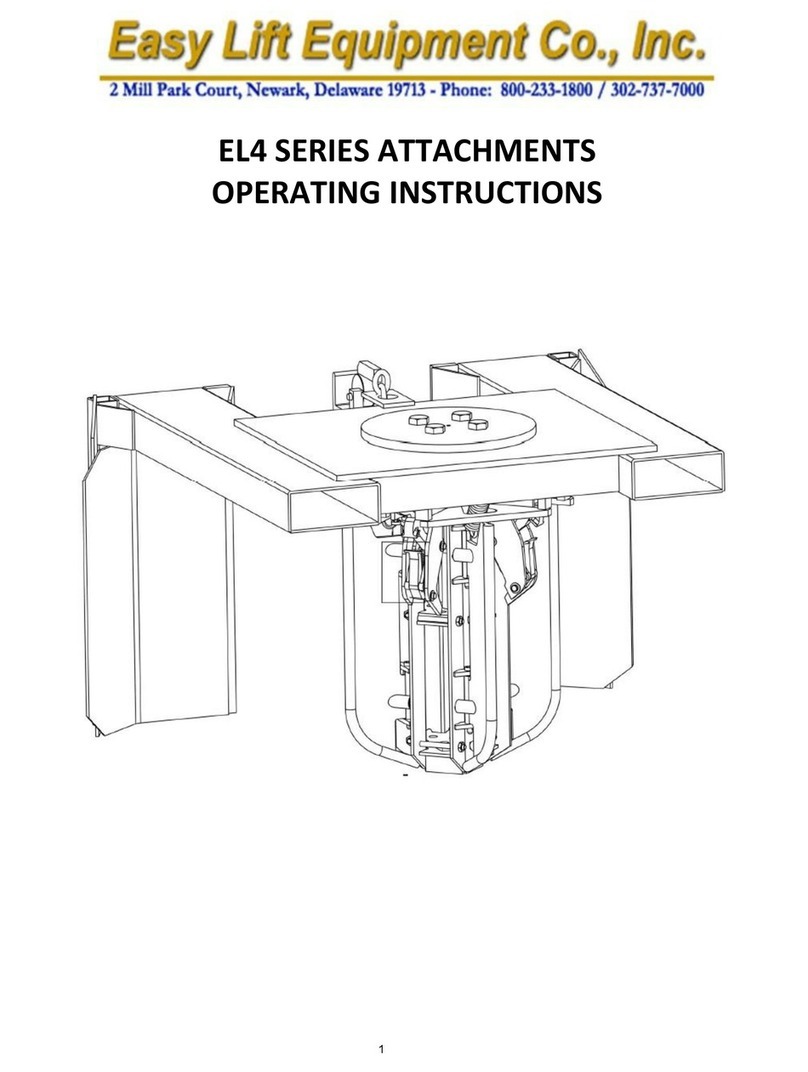
EAGLE-GRIP™ 4 SERIES ATTACHMENTS
OPERATING INSTRUCTIONS
11
WWW.EASYLIFTEQPT.COM

EASY LIFT EQUIPMENT
EAGLE GRIP 4™ SERIES ATTACHMENTS
INTRODUCTION
The Eagle-Grip™ 4 series of lift truck attachments utilize a heavy duty double automatic
clamping mechanism for handling any size steel or plastic chimed drum. The fork pockets and
safety chain provide a quick and easy connection to any lift truck. The specification plate affixed
to each attachment provides the following information: model number, serial number, attachment
weight, and lifting capacity. Please verify with your local forklift dealer that your lift truck,
counter-balanced walkie stacker, or walkie straddle stacker is certified and tagged
properly for this attachment.
This manual contains information to instruct you on the proper use and maintenance of your
Easy Lift Equipment unit. This manual should be available to all personnel working with the
machine. Follow the maintenance procedures carefully to ensure a safe and reliable service life.
Do not operate your equipment until you have read and understood these instructions.
COMISSIONING YOUR EAGLE GRIP 4 SERIES ATTACHMENT
1. Remove all packing materials, protective strapping, and wood shipping blocks.
2. Perform a visual inspection of the entire unit for damage.
3. Perform any necessary assembly based on the assembly diagrams located in this manual.
4. Drive the lift truck to position the forks inside the attachment.
5. Secure the attachment to the lift truck by connecting the safety chain to the forklift
carriage. The end of the chain is equipped with a snap hook, so generally the chain is
looped around the carriage and the snap hook is connected to the chain to form a loop.
6. The carriage mount version of this attachment will attach directly to any lift truck with an
ITA Class II carriage. Lower the lift truck carriage close to the ground. Pull up the
locking pin on the top rail of the attachment. Hook the top rail of the attachment over the
top rail of the carriage. Slide the attachment so the cleat on the lower rail can pass
through the cutout on the lower carriage rail and seat. Slide the attachment to the desired
location along the rail. Push the locking pin back down to ensure the attachment is
mounted securely to the lift truck carriage.
22

DAILY SAFETY INSPECTION
Do not operate your Eagle-Grip™ 4 series attachment if you notice any unsafe
condition(s) that may have been caused by an accident or malfunction. Immediately report
this condition to your supervisor.
1. Perform a visual inspection, checking for loose or damaged springs and jaws.
2. Ensure that safety chain is properly attached to carriage.
3. Ensure locking pins are pushed down and attachment is mounted securely to fork mount
carriage.
4. Ensure the operator has read the manual and is properly trained to use the attachment.
5. Observe the condition of the equipment for any other malfunction or defect.
If any of these tests are failed, tag the unit properly to keep it out of service until the
problem has been resolved.
SAFETY PRACTICES
1. Do not lift loads that exceed the rated capacity of the unit.
2. During transportation, the drum(s) should only be lifted to a height that is necessary for
proper floor clearance.
3. Keep hands and feet clear of the clamping head, lifting area in front of the unit, and the
area underneath an elevated drum.
4. Be certain the clamping head(s) have made a secure connection with the chime of the
drum before attempting to move or transport a load.
33

WARNINGS
WARNING: Do not lift or suspend loads over people. Stay clear of suspended loads.
WARNING: Do not attempt to overload the attachment its rated capacity, or raise the
drum(s) beyond its maximum lifting height.
WARNING: Never transport the attachment at its maximum lifting height.
WARNING: Keep hands and feet away from the pinch points, mast channels, clamp and
springs.
WARNING: Do not leave unit outside in rain, snow, etc., for extended periods.
WARNING: Never leave the unit unattended with a suspended load.
WARNING: Never wash the unit down. The unit is designed to be wiped down by hand.
WARNING: Do not make alterations or modifications to the unit without Easy Lift
Equipment authorization.
44

EAGLE GRIP 4 SERIES ATTACHEMENTS
OPERATING INSTRUCTIONS
TO ENGAGE AND TRANSPORT DRUMS:
1. Center the attachment clamping mechanisms with center of drum(s). Drive the lift truck
forward until the attachment contacts the drum(s).
2. Raise the carriage to engage the clamping mechanisms with the chimes of the drum(s).
The lift truck can now be driven to transport the drum(s).
3. Tilt the mast forward, then lower the carriage until the upper clamping jaw in the
clamping mechanism has retracted completely. The lift truck operator can now back
away.
TO ADJUST CLAMPING HEAD FOR VARIOUS DRUM HEIGHTS:
1. Lower the carriage as far as possible.
2. Remove adjustment pin, and lower or raise the clamping mechanism so that the lower
jaw is slightly below the bead or rim of the drum. It is advisable to have the cradle
touching the lowest possible point of the drum that still permits engaging the drum. The
second hole is suited for 55-gallon drums.
WHEN USING SLIDE-ON FORK MOUNTING WITH THE OPTIONAL QUICK-CLAW
SAFETY RESTRAINT SYSTEM
The patented "Quick Claw" cam locks hold the forks of the forklift securely to the
attachment. This option prevents any chance of sliding off during sudden stops. This also
eliminates the need for the operator to dismount the lift truck to secure or unsecure the standard
safety chain provided on all Eagle-Grip™ attachments. Unique rotating cams bind to the heel of
each fork when lifted off the ground. When the cam locks meet the floor, they conveniently
release the attachment. The fork pockets on all Eagle-Grip™ series attachments equipped with
Quick-Claw cams are 43” in length. This 43” length is designed for use on lift trucks equipped
with 42” length forks. The cam locks need to be in a position where the heel of the forks is
between 1.25” and 1.75” thick. The lift truck forks should be inspected prior to using the quick-
claw attachment to verify the fork thickness.
In the event the lift truck is equipped with 48” forks, 49” fork pockets will be necessary for
proper operation. If the attachment is not built to accommodate 48” length forks, the cam-locks
on the Quick-Claw option may not function properly.
55

SCALE EQUIPPED MODELS (GRIP & WEIGH ATTACHMENTS)
If your equipment has a scale system, the indicator has already been calibrated and tested
before leaving the factory. It has been disconnected and packaged separately for safe travel.
Unpack the indicator from the box and mount to the unit on the provided bracket. Connect the
indicator cable to the unit cable by screwing the male and female ends together. Turn on the
indicator and ensure it reads zero before engaging a drum. If handling liquids in a drum, it may
take up to one minute for the indicator to settle on a specific weight. To speed up this process it
is recommended to set the indicator to a lower sensitivity. This can be achieved by programming
the indicator to read in .5 pounds or .25 kilograms. If set to read in 1.0 or .5 kg. increments it will
take less time for the indicator to settle-down on a specific weight. Please refer to the manual of
the specific indicator for proper operation instructions.
Eagle-Grip™ Series Attachment Maintenance Checklist
Maintenance
Intervals
1
Mo
6
Mo
12
Mo
3
Yrs
Structural
Steel:
1.1
Check for cracked welds on frame
X
1.2
Flip attachment forward to inspect the ends of both fork pockets
for cracked welds
X
1.3
Lubricate the top and bottom rails of the fork mount frame to
permit the masts to slide left and right
X
1.4
Check masts to see if the 16” distance between the upper and
lower supports that slide on the fork mount frame have become
separated enough to the of point becoming unattached when
lifting a drum
X
1.5
Check the safety chain and cam lock for wear and missing parts
X
1.6
Check to verify that specification data plates are affixed to the
attachment
X
Clamping
Heads:
2.1
Inspect heads for loose or missing pins, cotter pins, springs, pins,
and replace as necessary
X
2.2
Lubricate clamping mechanisms
X
Belts:
3.1
Check belts for wear and adjust for proper tension
X
Pins, Springs,
Inner
housings,
Links:
4.1
Replace all springs
X
4.2
Replace all pins, inner housings, and links
X
Optional
Quick-Claw
5.1
Check to verify springs are intact and functioning properly
X
5.2
Lubricate cam to prevent rust
X
**The maintenance intervals refer to normal service conditions. In case of aggravated conditions, the intervals must be reduced/increased as required.
66

CLAMPING HEAD OR ATTACHMENT
PREVENTATIVE MAINTENANCE EXCHANGE & REFURBISHMENT PROGRAM
This service is designed to provide customers with an easy to use preventative maintenance
& refurbishment program to achieve the best performance and maximum service life. The
clamping mechanism(s) should have regular preventative maintenance service in addition to
required visual inspections, belt replacement, and monthly lubrication. The intervals between
services are dependent upon usage, but should generally be done at least once every year.
Loaner clamping head(s) or full attachment are provided free of charge however the
customer is responsible for all shipping costs incurred. Loaner attachments and clamping
mechanisms are finished in a different color to ensure identification as loaner units.
HOW IT WORKS:
•Contact Easy Lift Equipment or your local dealer to obtain a return authorization number
for your clamping head(s) or full attachment. If needed a loaner clamping head(s) or
attachment will be shipped to your site to minimize down time while your equipment is
being serviced
•Clamping head(s) only: remove the clamping head assembly from mast by removing the
circle cotter clip from the adjustment pin and pulling the adjustment pin out. Slide the
entire clamping head assembly up and out of the mast and reinsert the adjustment pin and
circle cotter pin.
•Ship the original clamping head(s) or full attachment to Easy Lift Equipment in the same
box, container, or pallet that the loaner was received. Be sure to display the return
authorization number and company name on the outside of the box, container, or pallet.
•The clamping head(s) or full attachment will be disassembled and assessed so a
maintenance quote can be provided for approval. Costs are determined by the required
parts, labor, and requested services or additional features.
SCOPE OF WORK TO BE PERFORMED: Clean and lubricate all necessary pins.
(Sandblasting, welding, and re-powder coating is available upon request). Replace
springs, jaws, cotter pins, or any worn parts. Reassemble clamping head(s) or full
attachment.
•Upon completion and approval, the clamping head(s) or full attachment will be returned
to the customer. The loaner clamping mechanism or attachment should be promptly
returned to Easy Lift Equipment.
The customer is responsible for all charges including but not limited to:
1. Parts & labor required for refurbishment or preventative maintenance.
2. Shipping to and from the company’s location.
3. Loss, damage, or repair(s) to the loaner equipment.
Should you have any questions regarding this progam, please call customer service at
800-233-1800 ext. 3, or your local dealer for clarification.
77

Capacity
Weight
H x L x W
Drums
Model
(lbs/kg)
(lbs/Kg)
(inches)
(mm)
Handled
Description
EG4DCM-CM
EG4DCMSRC-CM
2000/907
2000/907
110/50
110/50
33x15x18
33x15x18
838x381x457
838x381x457
1
1
Carriage Mount
Carriage Mount
EG4DCM-NF
EG4DCMSRC-NF
EG4DCM-NFQC
EG4DCMSRC-NFQC
2000/907
2000/907
2000/907
2000/907
253/115
253/115
341/155
341/155
37x47x24
37x47x24
42x47x24
42x47x24
940x1194x610
940x1194x610
1067x1194x610
1067x1194x610
1
1
1
1
Narrow Fork Mount
Narrow Fork Mount
Narrow Fork Mount/Quick Claw
EG4DCM-F
EG4DCMSRC-F
EG4DCM-FQC
EG4DCMSRC-FQC
2000/907
2000/907
2000/907
2000/907
330/150
330/150
418/190
418/190
37x47x33
37x47x33
42x47x33
42x47x33
940x1194x838
940x1194x838
1067x1194x838
1067x1194x838
1
1
1
1
Adjustable Fork Mount
Adjustable Fork Mount/Quick Claw
EG4DCM2-F
EG4DCMSRC2-F
EG4DCM2-FQC
EG4DCMSRC2-FQC
4000/1815
4000/1815
4000/1815
4000/1815
432/196
432/196
520/236
520/236
37x47x33
37x47x33
42x47x41
42x47x41
940x1194x838
940x1194x838
1067x1194x1042
1067x1194x1042
1 or 2
1 or 2
1 or 2
1 or 2
Adjustable Fork Mount
Adjustable Fork Mount/Quick Claw
PART# 4902
EGNF
EGNFQC
EGF
EGFQC
4000/1815
1500/680
1500/680
3000/1361
3000/1361
69/31
212/96
300/136
221/100
309/140
33x15x18
37x47x24
42x47x24
20x43x33
25x43x33
838x381x457
940x1194x610
1067x1194x610
508x1092x838
635x1092x838
Replacement Carriage Mount
Without Clamping Mechanism
Replacement Narrow Fork Mount
With Quick-Claw
Replacement Fork Mount Frame
with Quick-Claw
* All Carriage Mount models are made to fit an ITA Class II carriage unless otherwise specified
LOST LOAD CENTER:
The distance from the tip of the forks to the center of the drum (excludes CM models)
MODEL NUMBER
EG4DCM-CM & EG4DCMSRC-CM 23” from carriage to center of drum
12” from carriage to beginning of drum
EG4DCM-NF & EG4DCMSRC-NF 12” from end of pockets to center of drum
EG4DCM-NFQC & EG4DCMSRC-NFQC 12” from end of pockets to center of drum
EG4DCM-F & EG4DCMSRC-F 13” from end of pockets to center of drum
EG4DCM-FQC & EG4DCMSRC-FQC 13” from end of pockets to center of drum
EG4DCM2-F & EG4DCMSRC2-F 13” from end of pockets to center of drum
EG4DCM2-FQC & EG4DCMSRC2-FQC 13” from end of pockets to center of drum
VERTICAL CENTER OF GRAVITY:
The distance measured from the bottom of the attachment to the center point of the
carriage mount at which it balances.
MODEL NUMBER
EG4DCM-CM & EG4SDMSRC-CM 18.5”
EG4DCM-NF & EG4DCMSRC-NF 11.5”(w/43” Fork Pockets)
EG4DCM-NFQC & EG4DCMSRC-NFQC 14” (w/43” Fork Pockets)
EG4DCM-F & EG4DCMSRC-F 12” (w/43” Fork Pockets)
EG4DCM-FQC & EG4DCMSRC-FQC 14”(w/43” Fork Pockets)
EG4DCM2-F & EG4DCMSRC2-F 14”(w/43” Fork Pockets)
EG4DCM2-FQC & EG4DCMSRC2-FQC 16”(w/43” Fork Pockets)
88

HORIZONTAL CENTER OF GRAVITY:
The distance or point that is measured between the beginning of the fork pockets
to a middle point of the attachment which the attachment balances.
MODEL NUMBER
EG4DCM-CM & EG4DCMSRC-CM 6.5” from face of carriage
EG4DCM-NF & EG4DCMSRC-NF 30” (w/43” Fork Pockets)
EG4DCM-NFQC & EG4DCMSRC-NFQC 28” (w/43” Fork Pockets)
EG4DCM-F & EG4DCMSRC-F 30” (w/43” Fork Pockets)
EG4DCM-FQC & EG4DCMSRC-FQC 28” (w/43” Fork Pockets)
EG4DCM2-F & EG4DCMSRC2-F 33”(w/43” Fork Pockets)
EG4DCM2-FQC & EG4DCMSRC2-FQC 30”(w/43” Fork Pockets)
FOR PARTS, SERVICE OR TECHNICAL QUESTIONS CALL:
Easy Lift Equipment
2 Mill Park Ct.
Newark, DE. 19713
800-233-1800 ; 302-737-7000
FAX: 302-737-7333
www.easylifteqpt.com
43.0" 13.00"
42" Forks
22.50"
99

EASY LIFT EQUIPMENT WARRANTY POLICY
FOR MODELS WITH PREFIXES: ED/EL/ELDR/EG & RCR
Easy Lift Equipment (“ELE”) warrants each new Drum Hauler™ & Roll Hauler product to be free from factory
material and workmanship defects, under normal use with proper maintenance, for a period of 12 months.
Warranty coverage for this warranty period is provided by authorized dealers and includes parts. Labor is covered
for the same periods of 12 months as outlined above. Please call ELE for the authorized repair dealer in your area.
ELE shall be the sole judge of the validity of any claim or defect and may elect to make any replacement or repair
of any part thereof that it has agreed to be defective. Wearable Items: Such as hoses, bearings, belts, brake discs,
brushes, seals, springs and wheels are wear items and not covered under warranty. ELE assumes no liability
whatsoever to work done, parts replaced, or expenses incurred not specifically authorized by it. Normal
maintenance or replacement of service items is not covered by this warranty. No warranty claims will be
considered to customers with any delinquent outstanding balance. When batteries, battery chargers, scale printers
or scale indicators are purchased from ELE with the equipment, the original manufacturer’s warranty applies.
WARRANTY LIMITATION/DISCLAIMERS:
Easy Lift Equipment reserves the right to void warranty coverage if the unit has been overloaded beyond capacity
limitation, damaged due to misuse or abuse, neglect, accidents, freight damage. improper repair, improper storage
or that have been modified or repaired in any manner not approved by ELE. Equipment used in abrasive or
corrosive conditions, in freezers or excessive moisture, must be properly equipped for the environment to assure
the warranty is not voided. Warranty service and claims should be directed to our customer service department
who will contact a local authorized dealer or other representative in your area or we will assist the customer in
locating a local service representative in their area. The warranty described here above shall constitute the sole
remedy of the dealer and/or the initial purchaser. ELE shall under no circumstances be liable for special, general
incidental or consequential damages. ELE neither assumes nor authorizes any person to assume for it any other
obligation or responsibility in connection with this product warranty. In no event shall ELE be responsible for
direct, indirect, special or consequential damages or any other delay or any economic or commercial loss resulting
from Easy Lift Equipment’s performance or non-performance under this warranty. This warranty is expressly in
lieu of all warranties, obligations or responsibilities of ELE dealers or other authorized source, expressed or
implied or statutory.
SUBMITTING CLAIMS:
To make a claim under this guarantee, please contact Easy Lift Equipment for consideration. We can be reached
by calling 800-233-1800 then press 4 for customer service or by writing to sales@easylifteqpt.com. Do not
return defective parts unless a return authorization (RA) has been provided requesting for return. Do not send
defective parts to ELE unless requested. If requested, we will provide shipping information on how the part
should be returned and bear the expense for the return, if the part is proven to be defective.
A copy of the work order made at the time of the repair and parts claimed under warranty may be requested for
ELE’s inspection.
ORDERING PARTS:
Easy Lift Equipment’s products are distributed through a our service department and generally always ship the
same day when ordered. Parts are also available from many authorized dealers in your area. You will be well
taken care of whenever parts, adjustments or repairs are needed. When contacting ELE, please be sure to state
model number and serial number for the equipment. There is no cost for replacement manuals, parts lists and
other generally information containing part numbers and nomenclature. Most manuals contain parts pricing but
may not be current as parts pricing can change. Any customer service representative can provide timely parts
quotations upon request. Adherence to above procedure will save time and provide speedy assistance when it
counts. You are of course always welcome to bring to us any questions, comments or recommendations pertaining
to your Easy Lift Equipment products.
1010

HEAVY DUTY SINGLE DRUM FRAME
ASSEMBLY
13 12
11
10
9
20
19
18
1
14
15
4
3
5
8
7
6
3
2
16
17
Doc: M-HDSDF
Approver: Pat Dougherty
September 8, 2021
1212

ITEM PART NO. DESCRIPTION QTY
14902 Belt Cradle Frame - 5 hole (Belt Incl.) 1
1 4902-3 Belt Cradle Frame - 3 hole (Belt Incl.) 1
23516 Rubber Belt 1
22516 Composite Belt 1
3 12200-4 Belt Clamp (Yellow Powder Coating) 2
4 5/16-18 X 1 1/4 HHCS 5/16-18 x 1 1/4 Hex Head Cap Screw Grade 5 (zinc) 8
5 5/16-18 HN 5/16-18 Finished Hex Nut (zinc) 8
66902 Adjusting Rod for Belt Clamp 1
7 5/8 LW 5/8 Lock Washer (zinc) 1
8 5/8-11 HN 5/8-11 Finished Hex Nut (zinc) 2
90504D Cam, Cam Lock 1
10 4006-1 Pin, Cam Lock 1
11 6006-CP Cotter Pin, 5/32" x 1" (zinc) 2
12 0504A Clamp, Cam Lock (zinc) 1
13 504 Safety Chain & Cam Lock Assembly 1
14 1506 Roll Pin for Carriage Lock # 360061 (zinc) 1
15 36006-1 Pin, Lock to Carriage 1
16 2208 Slide on Mount Frame for EG3 & EG4 - 43" Length 1
16 2208QC Slide on Mount Frame with Quick-Claw for EG3 & EG4 - 43" Length 1
16 2208-49 Slide on Mount Frame for EG3 & EG4 - 49" Length 1
16 2208-49QC Slide on Mount Frame with Quick-Claw for EG3 & EG4 - 49" Length 1
17 ADART002 Attention Read Operations Manual Decal 1
18 MCL007031 Specification Plate 2
19 6 x 1/4 RUDS-SS 6 x 1/4 Round Head U Drive Screw (stainless steel) 8
20 ADART015 ELE Address Decal (Horizontal) 1
HEAVY DUTY SINGLE DRUM FRAME
PARTS LIST
Doc: M-HDSDF
Approver: Pat Dougherty
September 8, 2021
1313

HEAVY DUTY SINGLE DRUM
NARROW FRAME
ASSEMBLY
13
12
11
10
9
15
16
14
8
7
3
6
4
5
3
17
1
2
Doc: M-HDSDNF
Approver: Pat Dougherty
September 8, 2021
1414

ITEM PART NO. DESCRIPTION QTY
1 EGNF Narrow Fork Mount Frame for EG3 & EG4 1
1 EGNFQC Narrow Fork Mount Frame with Quick-Claw for EG3 & EG4 1
23516 Rubber Belt 1
2 3516SC Anti-Static Rubber Belt 1
22516 Composite Belt 1
3 12200-4 Belt Clamp (Yellow Powder Coating) 2
4 5/16-18 X 1 1/4 HHCS 5/16-18 x 1 1/4 Hex Head Cap Screw Grade 5 (zinc) 8
5 5/16-18 HN 5/16-18 Finished Hex Nut (zinc) 8
66902 Adjusting Rod for Belt Clamp 1
7 5/8 LW 5/8 Lock Washer (zinc) 1
8 5/8-11 HN 5/8-11 Finished Hex Nut (zinc) 2
90504D Cam, Cam Lock 1
10 4006-1 Pin, Cam Lock 1
11 6006-CP Cotter Pin, 5/32" x 1" (zinc) 2
12 0504A Clamp, Cam Lock (zinc) 1
13 504 Safety Chain & Cam Lock Assembly 1
14 ADART002 Attention Read Operations Manual Decal 1
15 MCL007031 Specification Plate 1
16 6 x 1/4 RUDS-SS 6 x 1/4 Round Head U Drive Screw (stainless steel) 4
17 ADART015 ELE Address Decal (Horizontal) 1
HEAVY DUTY SINGLE DRUM NARROW FRAME
PARTS LIST
Doc: M-HDSDNF
Approver: Pat Dougherty
September 8, 2021
1515

HEAVY DUTY DOUBLE DRUM FRAME
ASSEMBLY
20
1
4
3
5
18 19
2
6
3
7
8
16
17
9
12
10
11
14
15
13
Doc: M-HDDDF
Approver: Pat Dougherty
September 8, 2021
16

ITEM PART NO. DESCRIPTION QTY
14902 Belt Cradle Frame - 5 hole (Belt Incl.) 2
1 4902-3 Belt Cradle Frame - 3 hole (Belt Incl.) 2
23516 Rubber Belt 2
22516 Composite Belt 2
3 12200-4 Belt Clamp (Yellow Powder Coating) 4
4 5/16-18 X 1 1/4 HHCS 5/16-18 x 1 1/4 Hex Head Cap Screw Grade 5 (zinc) 16
5 5/16-18 HN 5/16-18 Finished Hex Nut (zinc) 16
66902 Adjusting Rod for Belt Clamp 2
7 5/8 LW 5/8 Lock Washer (zinc) 2
8 5/8-11 HN 5/8-11 Finished Hex Nut (zinc) 4
90504D Cam, Cam Lock 1
10 4006-1 Pin, Cam Lock 1
11 6006-CP Cotter Pin, 5/32" x 1" (zinc) 2
12 0504A Clamp, Cam Lock (zinc) 1
13 504 Safety Chain & Cam Lock Assembly 1
14 1506 Roll Pin for Carriage Lock # 360061 (zinc) 2
15 36006-1 Pin, Lock to Carriage 2
16 2208 Slide on Mount Frame for EG3 & EG4 - 43" Length 1
16 2208QC Slide on Mount Frame with Quick-Claw for EG3 & EG4 - 43" Length 1
16 2208-49 Slide on Mount Frame for EG3 & EG4 - 49" Length 1
16 2208-49QC Slide on Mount Frame with Quick-Claw for EG3 & EG4 - 49" Length 1
17 ADART002 Attention Read Operations Manual Decal 1
18 MCL007031 Specification Plate 1
19 6 x 1/4 RUDS-SS 6 x 1/4 Round Head U Drive Screw (stainless steel) 4
20 ADART015 ELE Address Decal (Horizontal) 1
HEAVY DUTY DOUBLE DRUM FRAME
PARTS LIST
Doc: M-HDDDF
Approver: Pat Dougherty
September 8, 2021
17

Doc: M-EG4
Approver: Pat Dougherty
March 2, 2022
18

ITEM PART NO. DESCRIPTION QTY
16202 Outer Housing (Black Powder Coating) 1
1 6202SS Outer Housing (Stainless Steel - Non-Sparking) 1
27902 Inner Housing (Black Powder Coating) 2
27902M Mauser Inner Housing (Black Powder Coating) 2
2 7902SS Inner Housing (Stainless Steel - Non-Sparking) 2
31007M Mauser Upper Clamp Jaw (Black Powder Coating) 2
3 1007SS Stainless Steel Upper Clamp Jaw (Non-Sparking) 2
45107M Mauser Lower Clamp Jaw (Black Powder Coating) 2
4 5107SS Lower Clamp Jaw (Non-Sparking) 2
572041 3/8" x 1-1/2" Pin, Link to Upper Jaw (zinc) 2
610061 1/2" x 2.182" Pin, Upper Jaw to Housing (zinc) 2
770091 Link, Jaw to Jaw 4
84306 Jaw Spring (zinc) 2
962041 3/8" x 2.13" Pin, Link to Lower Jaw (zinc) 2
10 9996 Hook, Housing Spring (Stainless Steel) 2
11 2206 Housing to Housing Spring (zinc) 2
12 18006-1 Pin, Housing to Housing (zinc) (HP10-305-E) 2
13 6006-CP Cotter Pin, 5/32" x 1" (zinc) 10
14 3/8-16 x 1 1/2 SHCS 3/8-16 x 1 1/2 Socket Head Cap Screw Alloy Plated 2
15 3/8 LW 3/8 Lock Washer (zinc) 2
16 10203-4 Spacer, Universal Body (Black Powder Coating) 1
17 9202 Universal Body (Black Powder Coating) 1
18 2016 1/2-13 x 2 Trunion Bolt (Zinc) 1
19 1906 1/2-13 LN, Trunion Lock Nut (Zinc) 1
20 10001 Bushing, Housing Yolk Trunion (zinc) 1
21 16009-1 Wear Plate, Universal Carrier 1
22 7202 Universal Carrier (Black Powder Coating) 1
23 19106-1 Adjustment Pin (zinc) 1
24 15106-1 Pin, Universal Body to Carrier (zinc) 1
25 1700-7 Adjustment Slide (Black Powder Coating) 2
26 8996 Clevis Spring Hook (Stainless Steel) 1
27 HANG-2 3/16 x 1-3/4 Circle Cotter "Hang 2" (7016) 1
28 3202 EG3 & EG4 Upper Clevis (With 3202P Pin) - 6-1/8" Length 2
29 17006-1 Pin, Clevis to Housing (HP10-370-E) 2
30 4206 Spring, Clevis (zinc) 2
31 3202P Clevis Replacement Pin with Cotter Pin 2
B-800 12oz White Lithium Grease Can 1
FULL ASSEMBLIES
32 6004 EG4 Double Clamping Mechanism (Black Powder Coating)
32 6004M EG4 Mauser Double Clamping Mechanism (Black Powder Coating)
32 6004SRC EG4 Double Clamping Mechanism (Stainless Steel - Non-Sparking)
PREVENTATIVE MAINTENANCE KITS
EG4PMKIT EG4 Preventative Maintenance Kit
EG4RBKIT EG4 Complete Rebuild Kit
EG4 HEAVY DUTY DOUBLE CLAMPING MECHANISM
PARTS LIST
Doc: M-EG4
Approver: Pat Dougherty
March 2, 2022
19

PART NO. DESCRIPTION QTY
4306 Jaw Spring (zinc) 2
2206 Housing to Housing Spring (zinc) 2
6006-CP Cotter Pin, 5/32" x 1" (zinc) 10
HANG-2 3/16 x 1-3/4 Circle Cotter "Hang 2" (7016) 1
4206 Spring, Clevis (zinc) 2
3516 Rubber Belt 1
B-800 12oz White Lithium Grease Can 1
PART NO. DESCRIPTION QTY
7902 Inner Housing (Black Powder Coating) 2
1007SS Stainless Steel Upper Clamp Jaw (Non-Sparking) 2
5107SS Lower Clamp Jaw (Non-Sparking) 2
72041 3/8" x 1-1/2" Pin, Link to Upper Jaw (zinc) 2
10061 1/2" x 2.182" Pin, Upper Jaw to Housing (zinc) 2
70091 Link, Jaw to Jaw 4
4306 Jaw Spring (zinc) 2
62041 3/8" x 2.13" Pin, Link to Lower Jaw (zinc) 2
9996 Hook, Housing Spring (Stainless Steel) 2
2206 Housing to Housing Spring (zinc) 2
18006-1 Pin, Housing to Housing (zinc) (HP10-305-E) 2
6006-CP Cotter Pin, 5/32" x 1" (zinc) 10
3/8-16 x 1 1/2 SHCS 3/8-16 x 1 1/2 Socket Head Cap Screw Alloy Plated 2
3/8 LW 3/8 Lock Washer (zinc) 2
2016 1/2-13 x 2 Trunion Bolt (Zinc) 1
1906 1/2-13 LN, Trunion Lock Nut (Zinc) 1
10001 Bushing, Housing Yolk Trunion (zinc) 1
16009-1 Wear Plate, Universal Carrier 1
8996 Clevis Spring Hook (Stainless Steel) 1
HANG-2 3/16 x 1-3/4 Circle Cotter "Hang 2" (7016) 1
3202 EG3 & EG4 Upper Clevis (With 3202P Pin) - 6-1/8" Length 2
17006-1 Pin, Clevis to Housing (HP10-370-E) 2
4206 Spring, Clevis (zinc) 2
3516 Rubber Belt 1
B-800 12oz White Lithium Grease Can 1
EG4 HEAVY DUTY PREVENTATIVE MAINTENANCE KIT
PARTS LIST
EG4 HEAVY DUTY COMPLETE REBUILD KIT
PARTS LIST
Doc: M-EG4PM
Approver: Pat Dougherty
January 27, 2022
20
This manual suits for next models
14
Table of contents
Other Easy Lift Equipment Lifting System manuals
Popular Lifting System manuals by other brands

Sabaj
Sabaj WP-560 Assembly and operating manual

Homeadapt
Homeadapt SRE-3000 Elan Operator's manual

Scaleo medical
Scaleo medical Poweo 140 Quick Up user manual

Nußbaum Hebetechnik
Nußbaum Hebetechnik 4.40H Instructions and Documentation

Arjo
Arjo Maxi 500 Operating and Product Care Instructions

ZORO
ZORO HT-05-1818A instruction manual