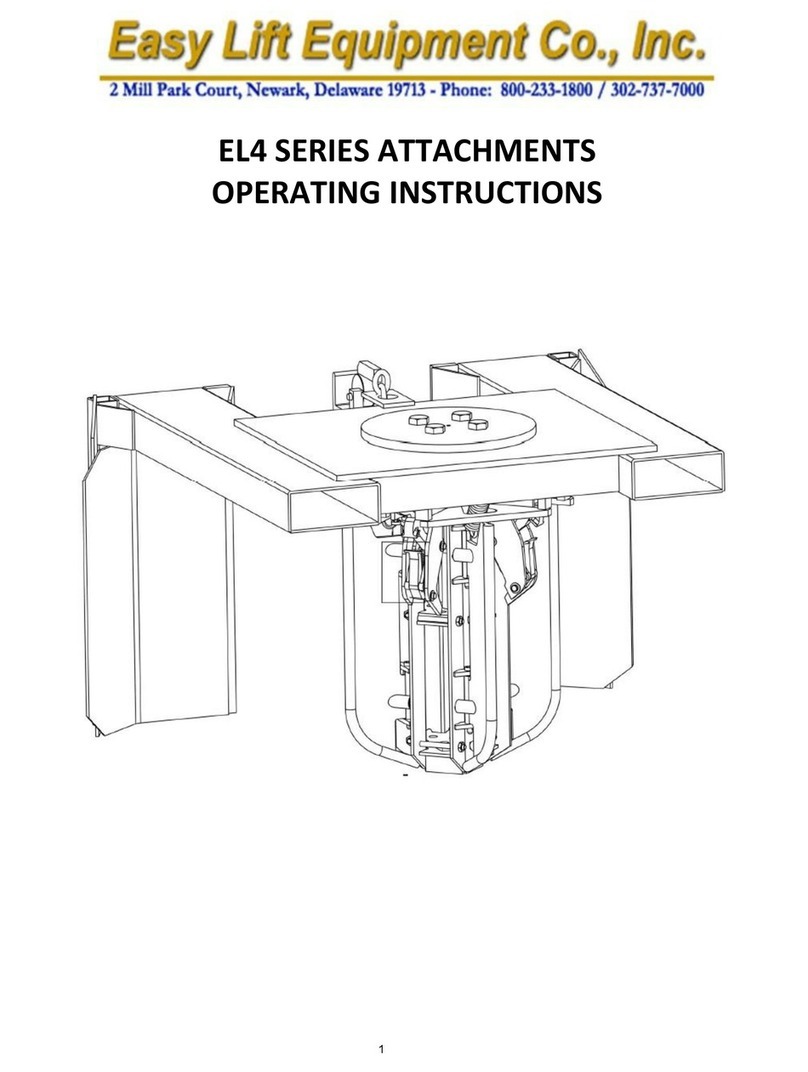
Easy Lift Equipment EAGLE GRIP EG4MDC2-F Operating instructions

OPERATING/MAINTENANCE
MANUAL
FOR
MODEL EG4MDC2-F
EMPTY DRUM HANDLING
ATTACHMENT
1

EASY LIFT EQUIPMENT
EMPTY DRUM HANDLING ATTACHMENTS
EAGLE GRIP® MODEL EG4MDC2-F
INTRODUCTION
The Model EG4MDC2-F empty drum handling attachments utilize a heavy duty double
magnetic clamping mechanism for handling 55-gallon size steel drums. The fork pockets and
safety chain provide a quick and easy connection to any lift truck. The specification plate affixed
to each attachment provides the following information: model number, serial number, attachment
weight, and lifting capacity. Please verify with your local forklift dealer that your lift truck,
counter-balanced walkie stacker, or walkie straddle stacker is certified and tagged
properly for this attachment.
This manual contains information to instruct you on the proper use and maintenance of your
empty drum handling attachment. This manual should be available to all personnel working with
the machine. Follow the maintenance procedures carefully to ensure a safe and reliable service
life. Do not operate your equipment until you have read and understood these instructions.
COMISSIONING YOUR EAGLE GRIP EG4MDC2-F ATTACHMENT
1. Remove all packing materials, protective strapping, and wood shipping blocks, then remove
the machine from the shipping pallet or crate.
2. Perform a visual inspection of the entire unit for damage.
3. Drive the lift truck to position the forks inside the attachment fork pockets and remove the
attachment from the pallet.
4. Secure the attachment to the lift truck by connecting the safety chain to the forklift carriage.
The end of the chain is equipped with a snap hook, so generally the chain is looped around
the carriage and the snap hook is connected to the chain to form a loop.
5. Lower the attachment on the forks and open the DC cabinet. Look at all the
components inside the cabinet to ensure nothing came loose when the equipment was in
transit.
6. Locate the key fobs which are stored in a plastic storage bag within the cabinet.
Remove one of the four key fobs and close the cabinet. The key fobs have been
programmed prior to shipping.
7. Locate the battery master disconnect switch on the outside of the cabinet and turn it to
the “ON” position.
Note: Each magnet has one green LED light on the top of the cabinet lid, another
underneath the attachment frame and one additional small LED light on the bottom of
the cabinet. There is also a small led blue light on the bottom of each magnet. The blue
light only illuminates when the master disconnect switch is in the “ON” position.
2

8. Press the key fob top button “ON”once to energize the magnets. All four green lights
on the cabinet lid should illuminate. There are also four green lights on the bottom of
the attachment which will also illuminate. Should they all not illuminate, press the
same key fob button “ON”again until all are illuminated. Then press the button on the
key fob “OFF”to de-energize the magnets. All lights should then be off. If a light
remains lit, press the right key fob button “OFF”once again. Continue this on and off
procedure until all light consistently turn on and off at the same time. Should there be
a consistent issue with all of the lights going on or off, try a different key fob until there
is no issue with this problem.
(See remote key fob programming section to correct memory in faulty remote key fob)
DAILY SAFETY INSPECTION
Do not operate your Eagle-Grip empty drum handling attachment if you notice any
unsafe condition(s) that may have been caused by an accident or malfunction. Immediately
report this condition to your supervisor.
1. Perform a visual inspection, checking for loose or damaged parts from previous use.
2. Ensure that safety chain is properly attached to carriage.
3. Check the battery discharge indicator to be sure the attachment has sufficient charge for
required usage.
Do not operate your empty drum handling attachment if you notice any unsafe
condition(s) that may have been caused by an accident or malfunction from previous
use. Immediately report any unsafe conditions or issues with the equipment to your
supervisor. Tag the machine properly to keep others from using it until the issue has
been corrected.
SAFETY PRACTICES
1. Do not lift drums that have any contents in them.
2. During transportation, the drum(s) should only be lifted to a height that is necessary for
proper floor clearance.
3. Keep hands and feet clear of empty drums once they are lifted. Steel-toe safety shoes
should be worn when manually handling empty steel drums.
4. Be certain the clamping head(s) have made a secure connection with the side of the drum
below the chime of the drum before attempting to move or transport the empty drums.
3

WARNINGS
WARNING: Do not lift the attachment or suspend loads over people.
Stay clear of suspended loads.
WARNING: Do not attempt to handle drum that have any contents in them.
WARNING: Never transport the attachment with drums being elevated more than a few
inches above floor level.
WARNING: Do not leave attachment outside in rain, snow, etc., for extended periods.
WARNING: Never leave the attachment unattended with a suspended load.
WARNING: Never wash down the attachment. The attachment is designed to be wiped
down by hand.
WARNING: Do not make alterations or modifications to the attachment without Easy Lift
Equipment authorization.
WARNING: Prior to handling drums stacked three high in a trailer it is necessary to
check the free lift of the lift truck mast. Be sure the lift truck mast and load
backrest will not contact the ceiling of the trailer.
WARNING: Exercise care when lifting drums stacked three high in trailers. The upright
portions on the attachment are about the same height as the empty drums
when lifted. Be sure not to lift the attachment too high and cause any
damage to the roof of the trailer or the attachment.
MAGNET REMOTE KEY FOB
4

EAGLE GRIP® 4 EMPTY DRUM HANDLING ATTACHEMENT
OPERATING INSTRUCTIONS
NOTE: The holding strength of the magnetics is dependent upon many factors. The
heavier the gauge of the drum sidewall, the better magnetic attraction to the metal.
Operator care in eliminating shock from traveling over dock plates and sharp turns should
be exercised. Operators should strive to clamp empty drums once when unloading to
reduce cosmetic abrasions where the magnets contact the drums. Magnets are equipped
with replaceable wear shoes to protect the magnets themselves from wear. Wear shoes
contact the drums and are powder coated to reduce cosmetic abrasions. Proper tension of
the belts is another important factor in ensuring drums are held securely –essentially the
belt must be positioned to ensure the drum is held vertical. The entire face of the magnet
should be in full contact against the flat surface of the drum sidewall so that magnet is flush
against the drum without any gaps at the top or bottom of the magnet. If gap is noticed
between these two surfaces at the top of the magnet, the belt that rests against the lower
side of the drum should be tightened. Belts will naturally stretch with use and may require
periodic adjusting to correct drum position and ensure proper alignment of the magnets.
Should a gap be noticed at the bottom of the magnet, the belt is too tight and should be
loosened to remove the gap.
TO ENGAGE AND TRANSPORT CLOSED HEAD EMPTY STEEL DRUMS
1. With the attachment properly secured to the lift truck and the disconnect switch in the
“ON” position, press the key fob button “ON”to illuminate all four green lights on top of
the DC cabinet cover. There are four additional green lights on the bottom of the
attachment which will also illuminate when the magnets are energized. In the event that
all four lights do not illuminate, continue to press the key fob button “ON”until all four
lights are illuminated. Do not attempt to grip empty drums unless all four green lights are
illuminated.
2. When all four green lights are illuminated, the magnets are now energized to grip the
drums. Level the forks on the lift truck. Center the attachment clamping mechanisms
with center of drum(s). Drive the lift truck forward with the clamping mechanisms in a
position to contact the empty drum(s). The clamping mechanism should make contact
against the upper third of the drum, above the second rolled hoop or “W” hoop of the
empty drum. The magnets will now engage the metal on the side on the empty drum.
In situations where the trailer is not on the same plane as the warehouse floor it would be
necessary for the lift truck operator to tilt the mast of lift truck forward or back to keep
the empty drums in a vertical (not tilted) position.
3. Raise the lift truck forks slightly to elevate the drums and back away. When removing
drums from trailers it is necessary to cross dock boards and ramps softly as shock from
bouncing from trailer to warehouse areas can cause the empty drums to release from the
magnets.
4. To release the drums onto the floor, pallet of conveyor the operator must not have
the lift truck carriage tilted forward or back. Doing so will only increase the chance
of abrasions to the drums’painted surface. Lower the drums just enough to contact
the floor, pallet or conveyor, then press the key fob button “OFF”to disengage the drums.
5

Do not back away until all four lights are no longer illuminated. Once released, the
operator can back away from the released drums, then press the key fob button “ON”
again to energized the magnets before entering the trailer to grip additional empty drums.
TO ENGAGE AND TRANSPORT OPEN HEAD EMPTY STEEL DRUMS
Open head steel drums with removable lids are wider than closed head drums. This requires one
of the two mast assemblies on the carriage frame to be repositioned outward to widen the distance
between the two masts assemblies by 1.6”. To widen the mast assemblies, lift the roll pin in the
carriage lock pin on either of the two mast assemblies and slide the mast assembly outward until
the carriage lock pin drops into the next slot in the carriage. This will increase the distance between
the two masts by the necessary 1.6”required to handle open head steel drums. Only move one of
the two mast assemblies, not both. Once this is done, follow the same instructions above for
handling closed head steel drums. When necessary to handle closed head drums again, this
procedure would be reversed to close the 1.6”gap.
Note: Drums with a third rolling hoop near the drums’ chime, such as a 17H drum, will not
work with this attachment. The is not enough space between the second rolled hoop and the
drums lid for the magnets to engage the drum.,
Note: All keys fobs are provided with a velcro tape attached to the back of the key fob. This
enables the key fob to be attached in a convenient location in the lift truck for the operator without
the need to be handheld.
CHARGING THE BATTERIES:
All EG4MDC2-F empty drum attachments are equipped with DC cabinet housing two large 12-
volt AGM batteries wired in series (24-volt system) to provide the power supply for activating the
magnets. Also inside of the DC cabinet is an automatic 24-volt charger. To charge the unit a
polarized heavy gauge extension cord rated 12-3 15amp / 125 volt is required but not provided.
To remove the attachment for charging:
1. Disconnect the safety chain securing the attachment to the lift truck, the remove the
attachment from the lift truck. Turn off the disconnect switch on the side of the cabinet to
the “OFF” position.
2. Open the cabinet lid, use a grounded medium heavy gauge extension cord and plug the
power cord from the charger into the extension cord.
3. The charger will shut off when the batteries are fully charged. A battery discharge indicator
located by the disconnect switch displays the state of charger for the batteries.
6

REMOTE KEY FOB REPROGRAMMING INSTRUCTIONS
ALL EG4MDC2-F ATTACHMENTS ARE PROVIDED WITH FOUR KEY FOBS
To Begin: With the attachment attached to the lift truck, elevate the attachment so the bottom of
the magnets are at eye level. This makes the programming process more ergonomic for the
operator rather than attempting to access the bottom of the magnets from floor level.
To Access the wireless teaching button: On the bottom side of every magnet there is an access
hole and two small LED lights, one blue and one green. These small lights are helpful when
reprogramming the key fobs. Use a 3mm Allen key to unthread the M5 cap screw on the bottom
of each magnet.
To Pair a Remote with a Magnet: With the screw removed, inset the 3mm Allen key into the
hole where the screw was removed until it touches the teach button inside the hole. Hold the
button in for 2 seconds to put the receiver in pairing mode. Within a few seconds of releasing
the teach button, push the key fob button “ON”. Then wait a few seconds for the key fob and
magnet receiver to pair. Then, test the pairing by pushing the key fob button “ON”again. The
green light on the magnet, the battery cabinet lid and underside of the attachment will illuminate.
Repeat this procedure until all four magnets have been paired with the same key fob.
Test the system by turning on and off all four magnets/green lights consistently.
If all four lights do not illuminate, continue to press the key fob button “ON”until all four lights
are illuminated. If one or more magnets do not pair, repeat the pairing process with the magnet
having the problem until all four magnets/green lights consistently turn on and off.
Re-closing the Magnet: When all programming is complete, insert all the M5 cap screw back
into the bottom screw hole of each magnet and tighten until snug.
NOTE: All Eagle-Grip® Attachments conform to OSHA standards. A metal plate, affixed
to each attachment, provides model number, serial number, rated capacity and attachment
weight. OSHA requires contacting the lift truck manufacturer for written approval of any
attachment to be used on a lift truck. Should the metal plate be missing - call for a free
replacement
7

MODEL EG4MDC2-F EMPTY DRUM HANDLING ATTACHMENT SPECIFICATIONS:
Model
Capacity
Weight
Height x Length x Width
Drums
Description
(lbs./kg.)
(lbs./kg.)
(inches)
(mm)
Handled
EG4MDC2-F
200/90.7
880/399.3
79x47x33
940x1194x838
1 or 2
Empty Drum Attachment
LOST LOAD CENTER: The distance from the tip of the forks to the center of the drum.
13” to center of drum measurement
VERTICAL CENTER OF GRAVITY: The distance measured from the bottom of the
attachment to the center point on the mast at which it balances. 9.75” with a fork mount
frame have 43” fork pockets.
HORIZONTAL CENTER OF GRAVITY: The distance or point that is measured between
the beginning of the fork pockets to the end of the attachment which the attachment
balances. 25.25”
FOR PARTS, SERVICE OR TECHNICAL QUESTIONS CALL:
Easy Lift Equipment
2 Mill Park Ct.
Newark, DE. 19713
800-233-1800 ; 302-737-7000
FAX: 302-737-7333
www.easylifteqpt.com
8

MAINTAINENCE CHECKLIST FOR MODEL EG4MDC2-F
EMPTY DRUM HANDLING ATTACHMENT:
Maintenance
Intervals
1
Mo
6
Mo
12
Mo
3
Yrs.
Structural
Steel:
1.1
Elevate the attachment to inspect for cracked welds
X
1.2
Check the safety chain for wear and missing parts
X
1.3
Check to verify that specification data plates are affixed to the
attachment
X
1.4
Check the gas struts on the battery compartment lid
X
Clamping
Heads:
2.1
Inspect heads for loose or missing pins, springs, screws and
replace as necessary
X
2.2
Check the magnet shoes for wear and replace when necessary.
X
Belts:
3.1
Check belts for wear and adjust for proper tension
X
Batteries:
4.1
Check battery voltage after charging
X
4.2
Check battery discharge indicator is functioning properly
X
Charger:
5.1
Check that battery cables and battery hold-downs are tight
X
5.2
Check that wiring on all LED lights is intact
X
9

Updated: 7/26/18
EASY LIFT EQUIPMENT WARRANTY POLICY
FOR MODELS WITH PREFIXES: ED/ER/EL/ELDR/EG & RCR
Easy Lift Equipment (“ELE”) warrants each new product to be free from factory material and workmanship
defects, under normal use with proper maintenance, for a period of 12 months. Warranty coverage for this
warranty period is provided by authorized dealers and includes parts. Labor is covered for the same periods of 12
months as outlined above. Please call ELE for the authorized repair dealer in your area.
ELE shall be the sole judge of the validity of any claim or defect and may elect to make any replacement or repair
of any part thereof that it has agreed to be defective. Wearable Items such as: hoses, bearings, belts, brushes,
seals, lift motors, clamp motors, relays, fuses, springs and wheels are wear items not covered under the warranty
policy. ELE assumes no responsibility whatsoever to work done, parts replaced, or expenses incurred not
specifically authorized by ELE. Normal maintenance or replacement of service items is not covered by this
warranty. No warranty claims will be considered for customers with any delinquent outstanding balance. When
batteries, battery chargers, scale printers or scale indicators are purchased from ELE with the equipment, the
original manufacturer’s warranty applies.
WARRANTY LIMITATION/DISCLAIMERS:
Easy Lift Equipment reserves the right to void warranty coverage if the unit has been overloaded beyond rated
capacity; damaged due to: abuse, misuse, neglect, accidents, freight damage, improper usage, improper repair,
and/or improper storage; or any modification or repair conducted in a manner not approved by Easy Lift
Equipment. Equipment used in freezers, abrasive, corrosive, and/or excessively moist conditions must be properly
equipped for the environment to ensure the warranty is not voided. Warranty questions and claims should be
directed to our customer service department. ELE customer service representatives will help you assess and
resolve the claim or assist you in contacting the local authorized dealer or representative. The warranty described
here shall constitute the sole remedy of the authorized dealer and/or the initial purchaser. ELE neither assumes nor
authorizes any person to assume for it any other obligation or responsibility in connection with this product
warranty. In no event shall ELE be responsible for direct, indirect, special or consequential damages or any other
delay or any economic or commercial loss resulting from Easy Lift Equipment’s performance or non-performance
under this warranty. This warranty is expressly in lieu of all warranties, obligations or responsibilities of ELE
dealers or other authorized source, expressed, implied or statutory.
SUBMITTING CLAIMS:
To make a claim under this policy, please contact Easy Lift Equipment for assistance. We can be reached by
calling 800-233-1800 ext. 4 for customer service or by writing to sales@easylifteqpt.com. Do not return
defective parts unless a return authorization (RA) has been provided requesting the return. If requested, we will
provide shipping information on how the part should be returned and bear the expense for the return shipping, if
the part is proven to be defective. A copy of the work order made at the time of the repair and parts claimed under
warranty may be requested for ELE’s inspection.
ORDERING PARTS:
Easy Lift Equipment’s parts are distributed through our customer service department and ship the same day as
ordered whenever possible. You will be well taken care of whenever parts, adjustments or repairs are needed.
When contacting ELE, please be sure to state the model and serial number for the equipment. There is no
cost for electronic copies of replacement manuals, parts lists and other general information containing part
numbers and nomenclature. Most manuals contain parts pricing, but it is not guaranteed to be valid as parts pricing
can change at any time without notice. Any customer service representative can provide timely parts quotations
upon request. Adherence to above procedure will save time and provide prompt assistance when it counts. You are
of course always welcome to bring to us any questions, comments or recommendations pertaining to your Easy
Lift Equipment products.
MANUFACTURER CONTACT INFORMATION:
Easy Lift Equipment Co., Inc. Phone: 800-233-1800: 302-737-7000
2 Mill Park Ct. Fax: 302-737-7333
Newark, DE 19713 Website: www.easylifteqpt.com
Email: sales@easylifteqpt.com
10

THIS PAGE INTENTIONALLY LEFT BLANK
11

Doc: M-EG4MAGC
Approver: Pat Dougherty
June 10, 2021
12

ITEM PART NO. DESCRIPTION QTY
13536202 Outer Housing (Stainless Steel - EG4 Magnet) 4
281401335 ELAY30x5 Magnet 4
3 3/8-16 x 1 1/2 SHCS 3/8-16 x 1 1/2 Socket Head Cap Screw Alloy Plated 4
4 3/8 LW 3/8 Lock Washer (zinc) 4
5 10203-4 Spacer, Universal Body (Black Powder Coating) 2
69202 Universal Body (Black Powder Coating) 2
7 1/2-13 x 2 SHCS 1/2-13 x 2 Socket Head Cap Screw (zinc) 2
8 1/2-13 NLN 1/2-13 Nylon Locking Nut 2
910001 Bushing, Housing Yolk Trunion (zinc) 2
10 16009-1 Wear Plate, Universal Carrier 2
11 7202 Universal Carrier (Black Powder Coating) 2
12 19106-1 Adjustment Pin (zinc) 2
13 15106-1 Pin, Universal Body to Carrier (zinc) 2
14 1700-7 Adjustment Slide (Black Powder Coating) 4
15 8996 Clevis Spring Hook (Stainless Steel) 2
16 HANG-2 3/16 x 1-3/4 Circle Cotter "Hang 2" (7016) 2
17 3202 EG3 & EG4 Upper Clevis (With 3202P Pin) - 6-1/8" Length 4
18 6006-CP Cotter Pin, 5/32" x 1" (zinc) 18
19 17006-1 Pin, Clevis to Housing (HP10-370-E) 4
20 4206 Spring (zinc) 4
21 36006-1 Pin, Lock to Carriage 2
22 1506 Roll Pin for Carriage Lock # 360061 (zinc) 2
23 4902-3 Belt Cradle Frame - 3 hole (Belt Incl.) 2
24 2516 Composite Belt 2
25 12200-4 Belt Clamp (Yellow Powder Coating) 4
26 5/16-18 HN 5/16-18 Finished Hex Nut (zinc) 16
27 5/16-18 X 1 1/4 HHCS 5/16-18 x 1 1/4 Hex Head Cap Screw Grade 5 (zinc) 16
28 6902 Adjusting Rod for Belt Clamp 2
29 5/8-11 HN 5/8-11 Finished Hex Nut (zinc) 4
30 5/8 LW 5/8 Lock Washer (zinc) 2
31 88001101 Pole Shoe Kit, Easy Lift 30x5 4
32 88001244 Hardware Kit, Easy Lift 30x5 4
33 88001245 Magnet Remote Control Kit 1
34 3202P Clevis Replacement Pin 2
EAGLE-GRIP® EMPTY DRUM HANDLING CLAMPING MECHANISM
PARTS LIST
Doc: M-EG4MAGC
Approver: Pat Dougherty
June 10, 2021
13

EAGLE - GRIP® EMPTY DRUM HANDLING
ATTACHMENT DC BOX ASSEMBLY
10 9
8
15
3
20
25
13
14
12
7
6
5
8
29
30
3
1
26
27
28
33
19
18
16
17
2
32
411
21
22
23
A
DETAIL A
36
31
35
34
37
24
Doc: M-EG4MAGD
Approver: Pat Dougherty
March 24, 2021
14

ITEM PART NO. DESCRIPTION QTY
13530510 DC Cabinet & Lid for Magnetic Drum Handling Attachment 1
2 CS24010628H Cabinet Hinge 1
3 WJ202 Hood Latch (730-1750) 1
4 PA16529 Master Disconnect Switch 1
5 DC210-12 12 volt, 210 AH AGM Battery 2
63530509 Battery Bracket for Magnetic Drum Handling Attachment 1
7 1/4-20 x 1 HHCS 1/4-20 x 1 Hex Head Cap Screw Grade 5 (zinc) 1
8 1/4-20 NLN 1/4-20 Nylon Locking Nut (zinc) 3
9 1/4 LW 1/4 Lock Washer (zinc) 1
10 1/4 FW SAE 1/4 Flat Washer SAE (zinc) 1
11 51064543 Battery Charger 115v/24v 30A (Magnetic Empty Drum Attachments ONLY) 1
12 51045638 USA AC Cable 1
13 T101772 24 Volt Battery Discharge Indicator (906T24JWDGN) 1
14 RSD-200B-24 DC /DC Converter 1 Output 24V 8.4 A 1
15 3530508 3/8-16 x 10" ALL THREAD 1
16 7527K64 Terminal Block (Strip) 7/16", 4 circuits 2
17 8-32 x 3/4 PTHS 8-32 x 3/4 Phillips Truss Head Screw (zinc) 4
18 8-32 NLN 8-32 Nylon Locking Nut (zinc) 4
19 A18033000UX0419 Green Indicator Light AC/DC 24V, 22mm Panel Mount 8
20 FT0831-50N 50N Hydraulic Gas Strut Lift Support Door Cabinet Hinge 2
21 3/8 FW 3/8 Flat Washer (zinc) 1
22 3/8 LW 3/8 Lock Washer (zinc) 1
23 3/8-16 HN 3/8-16 Finished Hex Nut (zinc) 1
24 97447A025 Aluminum Blind Rivet w/Aluminum Mandrel 1/8, .188-.25" 10
25 5/16-18 x 1 FSHCS-SS 5/16-18 x 1 Flat Socket Head Cap Screw (stainless steel) 4
26 5/16 FW 5/16 Flat Washer (zinc) 4
27 5/16 LW 5/16 Lock Washer (zinc) 4
28 5/16-18 HN 5/16-18 Finished Hex Nut (zinc) 4
29 8863T14 Loop Clamp with Vinyl Coated 1/2" OD, 1-7/16" Long 2
30 1/4-20 x 1/2 HHCS-SS 1/4-20 x 1/2 Hex Head Cap Screw (stainless steel) 2
31 6006-CP Cotter Pin, 5/32" x 1" (zinc) 1
32 ZZHEY3208 Cable Fitting 4
33 3530511 Magnetic Drum Handling Frame 1
EAGLE-GRIP® EMPTY DRUM HANDLING ATTACHMENT DC BOX
PARTS LIST
Doc: M-EG4MAGD
Approver: Pat Dougherty
March 24, 2021
15

POS.
NEG.POS.
NEG.
JUMPER
CABLE
12 VOLT
BATTERY
#2
#1
12 VOLT
BATTERY
BATTERY INDICATOR
12
43
16
6
MASTER
SWITCH
1112
L1L2
GND
110 AC PLUG
15
A
125
V
BATTERY CHARGER
POS.NEG.
DC INVERTER
9
10 amp
fuse
21
LIGHTSMAGNETS
3
10
25
3
2
8
4
18
2324
7
5
1
21
22
15
19
1413
17
2420
EAGLE GRIP EMPTY DRUM HANDLING
ATTACHMENT WIRING ASSEMBLY
Doc: M-EG4MAGW
Approver: Pat Dougherty
March 24, 2021
16

ITEM PART NO. DESCRIPTION QTY
1 PA16529 Master Disconnect Switch 1
2 DC210-12 12 volt, 210 AH AGM Battery 2
3 7527K64 Terminal Block (Strip) 7/16", 4 circuits 2
4 RSD-200B-24 DC /DC Converter 1 Output 24V 8.4 A 1
5 T101772 24 Volt Battery Discharge Indicator (906T24JWDGN) 1
6 113765-67-67-4 BLACK Battery Cable 4" - 4ga with (2) 5/16" Ring Terminal Ends 1
7 113766-67-68-5 RED Battery Cable 5" - 4ga with (1) 5/16" & (1) 3/8 Terminal Ends 1
8 51064543 Battery Charger 115v/24v 30A (Magnetic Empty Drum Attachments ONLY) 1
9 51045638 USA AC Cable 1
10 A18033000UX0419 Green Indicator Light AC/DC 24V, 22mm Panel Mount 8
11 210954-94-06 In Line Fuse Holder with (1) #3/8 and (1) #10 ends 1
12 PA82693 Auto Fuse, ATC Type, Red, 10A 1
13 DEK06120 Left Elbow Boot 4-8 GA Black 2
14 DEK06121 Left Elbow Boot 4-8 GA Red 2
15 80094UZ-06-06-3 3" Signal Wire with (2) #10 ends 1
16 80094UZ-06-29-4 4" Signal Wire with (1) .250 & (1) #10 end 1
17 80094UZ-06-29-6 6" Signal Wire with (1) .250 & (1) #10 end 1
18 80094UZ-06-06-24 24" Signal Wire with (2) #10 ends 1
19 81055UZ-06-06-3 3" Signal Ground with (2) #10 ends 1
20 81055UZ-06-29-7 7" Signal Ground with (1) .250 and (1) #10 end 1
21 81055UZ-06-06-24 24" Signal Ground with (2) #10 ends 2
22 81055UZ-06x4 (3) 3" Signal Ground Wires with (4) #10 ends 1
23 81055UZ-06-84-16 16" Signal Ground with (1) .250 and (1) #5/16 end 1
24 80094UZ-06-84-20 20" Signal Wire with (1) #10 & (1) #5/16 ends 1
25 81401335 ELAY30x5 Magnet 4
EAGLE-GRIP® EMPTY DRUM HANDLING ATTACHMENT WIRING
PARTS LIST
Doc: M-EG4MAGW
Approver: Pat Dougherty
March 24, 2021
17
Table of contents
Other Easy Lift Equipment Lifting System manuals