Easy Radiant Works GH40N Manual

1
12288 Brawn Rd, Wainfleet, Ontario, Canada L0S 1V0
INSTALLATION / OPERATING INSTRUCTIONS FOR
Easy Radiant “Works”
HEATWAVE
INFRARED RADIANT TUBE HEATER
MODEL NUMBERS
GH40N GH40P
40,000 BTU
LIQUID PROPANE OR NATURAL GAS
TECHNICAL DATA FOR VENTED RADIANT TUBE HEATER
5003356
ETL LIST
ED
COMFORMS TO
ANSI STD Z83.20
CERTIFIED TO
CSA STD 2.34
CGA/CSA STD 2.17
The installation must comply with local codes and CAN / CGA B – 149 in Canada
or the National Fuel Gas codes
WARNING: Improper installation,
adjustment, alteration, service or
maintenance can cause property damage,
injury or death. Read the installation,
operating and maintenance instructions
thoroughly before installing or servicing
this equipment.
AVERTISSEMENT. Une installation, un
réglage, une modification, une réparation ou un
entretien incorrect peut entraîner des dommages
matériels, des blessures ou la mort. Li sez
attentivement les instructions d’installation, de
fonctionnement et d’entretien avant de procéder à
l’installation ou àl’entretien de cet équipement.

2
INSTALLATION, OPERATING AND SERVICE MANUAL
FOR EASY RADIANT WORKS “HEATWAVE” MODEL GH40N/GH40P
GAS FIRED, VENTED INFRARED TUBE HEATER FOR RESIDENTIAL &
COMMERCIAL / INDUSTRIAL APPLICATIONS.
FOR YOUR SAFETY
IF YOU SMELL GAS Consignes De Securite
SI VOUS SENTEZ UNE ODEUR DE GAZ
1. Open windows 1. Ouvrez les fenetres
2. Do not touch electrical switches, or telephone 2. Ne touchez pas aux interrupteurs electriques
3. Extinguish any open flame 3. Eteignez toute flamme nue
4. Immediately call your fuel supplier 4. Contactez immediatement compagnie de gaz
5. If your gas supplier is not available, call the fire
department 5. Si votre fournisseur de gaz n’est pas disponible, appeler les
pompiers.
6. Do not attempt to light this or any other applicance 6. Ne pas tenter d’allumer ceci ou aucun autre appareil.
For Indoor Installation only. Not for use in residential dwellings
Installation a l’interieur seulement. Ne pas installer dans un logement.
INSTALLER
Please take time to read this manual completely to fully understand the instructions prior to the
installation. This manual must be left with the owner for future reference.
OWNER
Retain this manual in a safe place to provide your serviceman information if it becomes
necessary.
WARNING

3
Improper installation, adjustment, alteration, service or maintenance of this appliance will result
in property damage, serious personal injury or death. This appliance must only be installed by a
qualified, licensed and experienced gas fitter, familiar with the installation of this type of
appliance.
For your safety, do not use or store gasoline or other flammable vapours and liquids in the
vicinity of this or any other appliance.
The installation of this appliance must in all cases conform with local and national building
codes or in the absence of local codes with the current CAN/CGA B149.1&2 in Canada or
ANSI Z233.1 latest revision in the United States. This appliance has been tested and certified
for use in Canada and the United States.
Read This Manual Read this manual carefully before
installing or servicing this equipment.
Improper installation, servicing or
maintenance will cause death, injury or
property damage. Check the minimum
distance to combustibles, as noted on
the rating plate on the burner and on the
following pages of this manual to ensure
that the product is suitable for the
application.
Installer After the installation is complete, check
product operation as provided in these
instructions, and ensure that a proper
installation inspection, as is required in
your area, is completed.
This appliance is manufactured by: Easy Radiant Works
12288 Brawn Road
Wainfleet, Ontario,
Canada
L0S 1V0
Phone 905 899 3473
Fax 905 899 2262
www.easyradiantworks.com

4
CONTENTS OF THE SHIPPING BOX
Please check the carton and locate the items shown on this page.
Vent termination
5" (12.7 cm) Balanced flue consisting
of 1 - 5" (12.7 cm) vent pipe - 60 inches (or 5 ft) (1.5 meters)
long and 1- 3" flue pipe
66 (or 5’6”) (167 cm or 1.6 meters) inches long.
Bird Screen
Thermostat
Protective grill kits
(Optional)
ALSO INCLUDED . . . NOT SHOWN: ½" (1.2 cm) flexible gas connector, 5 ft. (1.5 meters)( #10 Jack chain
for hanging the heater, 2 vent centre guides.
OPTIONAL ACCESSORIES: 5 ft. (1.5 meters) vent extension kit, and 90-degree elbow kit.
Heater Assembly

5
INTRODUCTION
Heater specifications “Heatwave” Model GH40N (Natural Gas) GH40P (Liquid Propane)
Electrical: 120VAC / 60 Hz / 1-Ph / 1A
Connection: 3 pin grounded plug
Gas Inlet Connections:
Connection: ½" (1.2 cm) Male NPT
BTU/hr.
Natural gas & L.P. (Propane)
Minimum 40,000 BTU
Maximum 40,000 BTU
Gas Inlet Pressure
Natural Gas:
Minimum inlet 7.0" w.c.
Maximum inlet 14.0” w.c.
L.P. (Propane)
Minimum inlet 11.5" w.c.
Maximum inlet 14.0" w.c.
Manifold Pressure
Natural Gas: 3.5" w.c.
L.P. (Propane) 10.0" w.c.
Venting Specifications:
Maximum length: 12 ft. (3.6 meters)
Minimum length: 2 ft. 6" (.7 meters)
Maximum 1 - 90 degree elbow
Flue pipe - 3.0" (7.6 cm) diameter
Vent pipe - 5.0" (12.7 cm) diameter
Important: only flue pipe and vent pipe
supplied by the manufacturer may be used.
19.5 m
40.6 cm
24.1 cm
15.2 cm
35 cm
40.6 cm
22.2 cm

6
Where can the heater
be installed?
The Heatwave GH40N/GH40P garage
heater is intended for use in the
following areas:
- residential garages
- workshops
Light commercial / industrial
applications such as:
- entranceways - storage rooms
- lobby areas - manufacturing areas
- lunch rooms - agricultural buildings
Where can’t the heater
be installed?
The Heatwave GH40N/GH40P garage
heater is not intended for use in
residential living spaces or basements.
Installers responsibility The Heatwave heater, as well as the gas and
electrical supply, and the venting of the heater
must be installed in accordance with applicable
specifications and codes. Only firms (or
individuals) well qualified in this type of work
should install the system. Consult local
Building Inspectors or Fire Marshals for
guidance. Use the information given in this
manual together with the cited codes and
regulations to perform the installation. If any
aspects of this installation process are unclear,
consult Easy Radiant Works before
proceeding.
The installer must furnish all materials required
that are not furnished with the heater. It is also
the installer’s responsibility to see that the
materials and installation methods used, result
in a job that is workmanlike in appearance and
is in compliance with all applicable codes and
requirements of this manual.

7
The type of gas appearing on the nameplate must be the type of gas used. Installation must
comply with local codes and recommendations of the local gas supplier. If fuel used, does not
match the fuel listed on the nameplate, discontinue use immediately and contact Easy Radiant
Works for information on converting the appliance to the appropriate fuel.
VENTING REQUIREMENTS
The Heatwave heater MUST be installed with the venting system supplied with the heater, or
one of the optional venting kits available from Easy Radiant Works. DO NOT connect the
heater to a separate chimney and DO NOT common vent with any other fuel-burning appliance.
The Heatwave heater employs a balanced flue/air venting duct system and must conform to the
following minimum and maximum vent requirements. The location, size, installation and
termination of vents, as well as the minimum safe distances when penetrating combustible
walls, must comply with local codes, national codes and the recommendations of the local gas
company.
Maximum vent length: 12 feet (3.5 m) plus 1 elbow (elbow available from manufacturer).
Minimum vent length: 2 ft. 6 inches (.76 meters)
The balanced flue consists of a 3"(7.6 cm) diameter flue that is concentrically positioned inside
a 5” (12.7 cm) diameter pipe (see above). The 5" (12.7 cm) diameter pipe supplies outside air
that is necessary for combustion, while the 3" diameter flue carries the products of combustion
from the heater. The 3” (7.6 cm) and 5” (12.7 cm) pipes are separated by the centering guides
supplied with the heater. The balanced flue is applicable for horizontal venting arrangements
only.

8
COMMERCIAL/INDUSTRIAL APPLICATIONS
Aircraft
Hangers
The Heatwave heater may be used in certain areas of aircraft
hangers. The installation must be in accordance with local and
national codes.
Heaters in aircraft, storage or service areas must be installed
a minimum of 10 ft. (3 meters) above the upper surface of
wings or engine enclosures of the highest aircraft that may
be housed in the hanger. (This should be measured from the
bottom of the heater to the top of the wing, or engine
enclosure, whichever is highest from the floor.)
In other sections of aircraft hangers, heaters must be
installed a minimum of 8 ft. (2.4 meters) above the floor.
Heaters installed in aircraft hangers shall be located so as
not to be subject to damage by aircraft, cranes or other
objects.
When installed over hoists, the minimum required safe
distances to combustibles must be maintained from the
uppermost point of the combustible materials placed on the
hoist.
Public Garages The Heatwave heater may be used in public garages provided the
installation conforms to all local and national codes for the
installation of gas burning appliances.
Heaters must be installed a minimum of 8 feet (2.4 meters)
above the floor. Minimum safe distances to combustibles
must be maintained.
When installed over hoists the minimum required safe
distances to combustibles must be maintained from the
uppermost point of the combustible materials placed on the
hoist.
HAZARDOUS LOCATIONS
When there is a possibility of exposure to combustible airborne material or vapour, consult the
local Fire Marshal, the Fire Insurance carrier or other authorities for approval of the proposed
installation.

9
GENERAL INSTALLATION PROCEDURES
CHOOSING A SAFE LOCATION
When selecting a suitable mounting location for the heater, it is important to consider the following:
The heater must be installed with a minimum of 7 ft. (2.1 meters) between the floor and the bottom of
the heater in Canada. In the United States it must be installed with a minimum of 8 ft. (2.4 meters)
between the floor and the bottom of the heater, unless the optional protective grill is used, in which case
it may be installed with a minimum of 7 ft. (2.1 meters) between the floor and the bottom of the heater.
(See grill installation procedure, page 16)
The proposed mounting location allows for the minimum required safe distances to combustibles,
including vehicles that may be parked in the building, wood, gasoline and flammable objects, liquids
and vapours that may be stored in the space.
The proposed location will not restrict motion of passageway doors or windows, or the operation of the
overhead garage door.
The proposed location will provide the best coverage of the total area to be heated.
The proposed location will allow the required utilities (i.e. gas, and electric) and venting to be installed
(bearing in mind the minimum and maximum vent length requirements).
Sufficient clearances will exist to allow for maintenance.
Overhead structural members are available, and suitably strong to support the heater assembly.
GENERAL GUIDELINES
Regardless of the vent arrangements that will be connected to the heater, the following general guidelines for
venting must be followed:
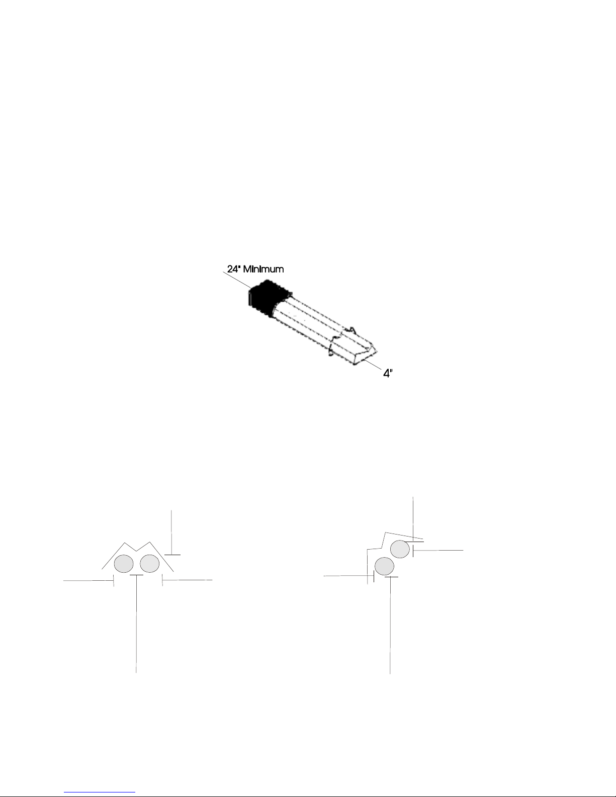
The 3" (7.6 cm) flue pipe must be centered inside the 5" (12.7 cm) air supply pipe using the centering
guides supplied.
IMPORTANT: THE FLUE PIPE AND AIR SUPPLY PIPE MUST BE SECURE. IF NOT SECURE,
THIS WILL CAUSE DAMAGE TO THE HEATER AND VOID WARRANTY.
All horizontal venting sections must slope away from the heater at a rate of 1/4" (6 mm) per foot.
The total length of vent pipe (horizontal and vertical) must not exceed 12 ft. (3.6 meters) and must not
be less than 2 ft. 6 inches (.7 meters)
The vent terminal, mounted outside of the building should not be located above walkways. Condensate
produced during operation of the heater could drip onto the walkway and form ice during cold weather
resulting in a dangerous condition.
Be sure that the venting installation is in accordance with all applicable local codes and
recommendations of the local gas supplier.
DO NOT connect the heater to a separate chimney, and DO NOT common vent with any other fuel-
burning appliance.
Seal all vent pipe connections with high temperature silicone sealant and secure each connection with
three sheet metal screws.

10
GENERAL INSTALLATION PROCEDURES
MINIMUM SAFE DISTANCES
In all situations, the minimum required clearances to combustibles must be maintained. Combustibles are
materials that may catch on fire, and include many common items such as wood, paper, rubber, fabrics, etc.
Combustible material such as those noted, and any other combustible materials must not be placed closer to any
base or side of the heater that the distances noted on the diagrams on the following page. If you have any
questions concerning safe distances to combustibles contact Easy Radiant Works prior to proceeding.
It is important to keep the minimum required safe clearances to combustibles at all times to avoid death,
personal injury or property damage. Clearances to vehicles parked beneath heaters must be maintained. Signs
should be posted to identify any possible violation of the clearances. Maximum allowable stacking height in
storage areas should be identified with signs or appropriate markings. The illustrations following identify the
minimum required safe clearances to combustibles.
60.9 cm
MINIMUM CLEARANCES TO COMBUSTIBLES
HORIZONTAL MOUNTING ANGLE MOUNTING
18”
46cm
18”
46cm
32”
8
1
c
m
4”
10cm
1
8
”
4
6
c
m
3
2
”
8
1
c
m
4
”
1
0
c
m
Angledback
4”
10cm

11
IMPORTANT
The clearance to combustibles “below” (32 inches) (81 cm) indicates the safe clearance to combustibles and
NOT the minimum mounting height.
CLEARANCES TO COMBUSITBLES
The clearance to combustible materials represents the minimum distance that must be maintained between the
heater and a nearby surface.
The stated clearance to combustibles represents a surface temperature of 90 degree Fahrenheit (32 degrees
Celsius) above room temperature. Building material with a low heat tolerance may be subject to degradation of
lower temperatures. It is the installer’s responsibility to assure that adjacent material are not subject to
degradation.
A warning statement that an overhead heater should be installed so that the minimum clearances marked on the
heater will be maintained from vehicles parked below the heater.
Minimum clearances (inches) from combustibles measured from radiant surface.
Clearances are reduced by 1/3, 15 ft (4.6 meters) from the burner.
For installation at elevations above 2000 ft (610m), the appliance shall be de-rated 4 percent for each 1000 ft
(305m) of elevation above sea level.
GAS CONNECTION
A qualified and licensed technician must do all gas piping and connections. All gas piping must be done in
accordance with all local codes and CAN / CGA B 149 and ANSI standards Z223.1
A 1/8” (.3 cm) NPT plugged tapping accessible for test gauge connection must be supplied immediately
upstream of the gas supply connection to the heater. A drip leg must be installed in the gas line at the heater
connection.

12
GENERAL INSTALLATION PROCEDURES
HEATER ORIENTATION
The HeatWave heater may be installed in either of the following orientations:
horizontally
tilted - 45 degree angle
For Horizontal installation (see drawing below):
Using “S” hooks; attach four equal lengths of #10 jack chain (or equivalent) to the 4 holes in the front
fixed hangers.
Connect the 2 free ends of the chain to another “S” hook, as shown.
Connect a length of chain from the uppermost “S” hook to the suspension hardware you have previously
installed in the ceiling to support the heater.
Connect a length of chain to an “S” hook and slip the “S” hook under the center portion of the rear
movable hanger. Connect the free end of this chain to the hardware you have previously installed in the
ceiling to support the heater. Ensure that the heater is parallel to the floor.
For Angled Installation:
Adjust the chain lengths at the front fixed hanger to achieve the appropriate angle.
Use side suspension point on the rear movable hanger.
Horizontal Mounting
Angled or tilted Installation

13
TYPICAL INSTALLATION
Vent
terminal
Min. 24” (61 cm)
Burner Box
Exterior
Wall
Floor
Movable
hangar
Minimum mounting
height 7 ft (2.1 meters)
16” (40.6 cm)
Minimum 7 ft (2.1 meters)
Minimum 6” (15.2 cm)
Minimum mounting height in United States between bottom of tube and floor is 8 ft. (2.4
meters)(7 ft. or 2.1 meters, if optional protective grill is used)

14
VENTING INSTALLATION
HORIZONTAL VENTING
After the heater has been properly suspended according to this manual, proceed to install the venting as
described below:
Measure the distance from the floor to the center of the vent collar on the rear of the burner. Transfer
this measurement to the inside surface of the exterior wall that the vent will penetrate, and make a mark.
Measure the distance between the exterior wall and the vent collar on the rear of the heater. If the
distance between the rear surface of the heater and the exterior wall is greater than 5 ft. (1.5 meters), a
vent extension kit (available from the manufacturer) is required.
For each lineal foot of distance from the heater to the wall, measure down vertically (on the outside
wall) 1/4 inch (.6 cm) from the previous reference mark. This new mark is the center of the hole that
must be cut to accommodate the 5” (12.7 cm) vent. Cut the hole in the exterior wall.
Install the 3” (7.6 cm) flue pipe from the vent collar on the rear of the burner through the exterior wall.
The flue pipe must extend a minimum of 6” (15.2 cm) beyond the exterior wall. Install the centering
guides over the 3” (7.6 cm) flue.
IMPORTANT: THE FLUE PIPE AND AIR SUPPLY PIPE MUST BE SECURE. IF NOT SECURE,
THIS WILL CAUSE DAMAGE TO THE HEATER AND VOID WARRANTY.
Cut the 3” (7.6 cm) flue pipe to the appropriate length. All joints must be sealed with high
temperature silicone adhesive and be secured with 3 sheet metal screws.
Assemble and cut if necessary, the 5” (12.7 cm) vent to run between the vent collar on the heater to
the exterior wall. All joints must be sealed with high temperature silicone adhesive.
From the exterior of the building, slip the 5" (12.7 cm) air supply pipe over the installed 3” (7.6 cm)
flue pipe and centering guides. Connect the 5” (12.7 cm) pipe to the vent collar on the heater and
seal with silicone adhesive and secure with 3 sheet metal screws.
From the exterior of the building, slip the vent terminal onto the 3” (7.6 cm) flue pipe and guide the
sleeve portion of the vent terminal into the 5” (12.7 cm) air supply pipe. Secure air vent pipe to the
vent terminal with silicone adhesive.
Secure the vent terminal to the exterior surface of the wall.

15
VENT ELBOW ASSEMBLY
INSTALLING HORIZONTAL VENTING WITH AN ELBOW
After the heater has been properly suspended in accordance with this manual, proceed to install the venting
and 90-degree elbow as described below.
Note: a 90-degree elbow kit (available from the manufacturer) is required for this installation.
Measure the distance from the floor to the middle of the vent collar on the rear of the heater, and
transfer this measurement to the exterior wall that will be penetrated with the vent.
Measure distance “A” and “B” as shown above. If this distance (A plus B) is greater than 5 ft. (1.5
meters), a vent extension kit (available from the manufacturer) is required.

16
GENERAL INSTALLATION PROCEDURES
INSTALLING HORIZONTAL VENTING WITH AN ELBOW (CONTINUED)
For each linear foot of measured distance (total of A plus B) measure down vertically ¼” (6mm) from
the reference mark on the exterior wall. This new reference mark is the centerline of the clearance hole
for the 5" (12.7 cm) vent that must be cut in the wall. Proceed to cut the hole in the exterior wall after
measuring carefully.
Attach the 3" (7.6 cm) elbow portion of the 90-degree elbow kit to the 3" (7.6 cm) flue pipe (length A).
Use silicone adhesive and 3 sheet metal screws.
Slip the 5" (12.7 cm) air supply pipe over the plain end (without elbow) of the assembled 3" (7.6 cm)
flue pipe and elbow.
Attach plain end of the 3" (7.6 cm) flue pipe to the rear of the burner box using silicone sealant and 3
sheet metal screws.
Attach 5" (12.7 cm) air supply pipe (length A) to the vent collar on the rear of the burner box using
silicone sealant and 3 sheet metal screws.
Assemble the 90-degree elbow in accordance with the instructions included with the elbow. Secure
length “A” of the 5" (12.7 cm) air supply pipe to the elbow assembly using silicone sealant and 3 sheet
metal screws.
Attach length “B” of the 3" flue pipe to the 3" (7.6 cm) elbow using silicone and sheet metal screws.
NOTE: the 3" (7.6 cm) flue pipe must extend a minimum of 6" (15.2 cm) beyond the exterior wall. Cut
if necessary to the appropriate length. Install centering guides over the 3” (7.6 cm) flue pipe.
From the exterior of the building, slip the 5" (12.7 cm) air supply pipe over the installed 3" (7.6 cm) flue
pipe and centering guides. Connect the 5" (12.7 cm) pipe to the 90-degree elbow assembly using
silicone adhesive and sheet metal screws.
From the exterior of the building, slip the vent terminal onto the 3" flue pipe and guide the sleeve
portion of the vent terminal into the 5" air supply pipe that is connected to the rear of the burner box.
Secure the air vent pipe to the vent terminal with silicone adhesive.
Secure the vent terminal to the exterior of the building.
IMPORTANT: THE FLUE PIPE AND AIR SUPPLY PIPE MUST BE SECURE. IF NOT SECURE,
THIS WILL CAUSE DAMAGE TO THE HEATER AND VOID WARRANTY.

17
GENERAL INSTALLATION PROCEDURES
BIRD SCREEN INSTALLATION
The bird screen is supplied in order to prevent blockage of the flue vent by birds or other small animals nesting
in the flue. It must be installed directly at the end of the 3” (7.6 cm) flue.
orient the bird screen so that the flat surface is toward the exterior.
insert the screen into the inside diameter of the 3” (7.6 cm) flue pipe.
secure the bird screen with a sheet metal screw.
ELBOW ASSEMBLY
If you are using the balanced flue elbow, assemble it in accordance with the instructions below.
install the spacer.
insert the 3” (7.6 cm) elbow into the 5" (12.7 cm) elbow.
ELECTRICAL SERVICE INSTALLATION
The HeatWave heater requires a grounded 3-prong electrical outlet to be installed within 3 ft. (.9 meters) of the
rear surface of the heater’s burner box. Extension cords may not be used. It is recommended that the outlet for
the heater be ceiling mounted and should be a dedicated circuit.
Heater rating: 120 VAC, 60 Hz, Single Phase, and 1 amp
The heater must be electrically grounded in accordance with the following codes: Canada: Refer to Canadian
Electrical code, CSA C22.1 Part-1 latest revision. In the United States refer to National Electrical Code,
ANSI/NFPA-70- latest revision.
THERMOSTAT
A 24 VAC thermostat, supplied with the heater, controls the Heatwave. Thermostat wire is not supplied.
Purchase 18 - 22 AWG double strand wire for this purpose.
Mount the thermostat on an exterior wall whenever possible.
Mount the thermostat approximately 5 ft. (1.5 meters) above the floor.
Mount the thermostat so that it is not in the direct ray of infra red energy from the heater.
Connect one end of the thermostat wire to the 2 terminals on the thermostat. Run the thermostat wire to the
thermostat connection on the rear of the burner box. Make sure that the thermostat wire is free of staples or
tacks as this can interfere in the operation of the thermostat.
GAS SERVICE INSTALLATION
A ½ inch (1.2 cm) gas connection is required at the rear of the heater. All gas supply piping must be done by a
qualified and licensed professional familiar with the installation of this type of appliance. All gas piping must
be in accordance with all local and nation codes on the installation of gas burning appliances. DO NOT
ATTEMPT TO RUN GAS LINES YOURSELF. This could result in loss of life, serious injury and/or property
damage.

18
GRILL INSTALLATION
The protective grill is optional. The protective grill must be used for installations in the United States where the
distance from the bottom of the heater to the floor is less than 8 ft. (2.4 meters) If using the protective grill for
installations in the United States, the bottom of the heater may be a minimum of 7 ft. (2.1 meters) above the
floor.
OPERATING SEQUENCE
The Easy Radiant gas burner is a very simple device. The normal sequence of events during ignition and
operation of the burner is as follows:
1. The heater is energized by means of a thermostat or switch.
2. When 24 volts is applied to the module, the module will energize the blower and close the airswitch.
3. The current flows and energizes the igniter and reaches ignition temperature. No gas flows until the
valve is energized and opened.
4. Air pressure generated by the blower will cause the normally open combustion pressure switch to close.
The combustion pressure switch is set to allow the normal rate of combustion air to flow into the
combustion chamber. Any restriction or blockage will cause the pressure switch to open and shut down
the entire system.
5. The current passes through the blocked flue pressure switch, which is normally closed. Any blockage or
restriction will cause the pressure switch to open and shut down the entire system.
6. After 17 seconds, the valve is energized and opened. Gas flows through the burner and is ignited.
7. The power is removed from the igniter. The flame sensor is utilized. As long as a flame is present, the
valve is held open. If the flame is lost, the control acts to close the valve within one second and a new
trial sequence to start up is initiated.
8. If ignition is not achieved, or flame is not sensed, then the control closes, the gas valve, and attempts
ignition a second time, and if necessary a third time. If ignition is not achieved after the third try, the
control goes into lockout for 30 minutes and power must be interrupted before trying again. At this
point it is suggested that an authorized service person be contacted to inspect and test the controls.
9. The heater should continue to function until power is interrupted either by the thermostat being satisfied
or manually disconnected.
WARNING
THIS HEATER MUST BE INSTALLED AND SERVICED BY A TRAINED GAS SERVICE TECHNICIAN
ONLY. READ AND UNDERSTAND THESE INSTRUCTIONS THOROUGHLY BEFORE ATTEMPTING
TO INSTALL, OPERATE OR SERVICE THE EASY RADIANT WORKS HEATER. FAILURE TO
COMPLY WITH THESE WARNINGS AND INSTRUCTIONS, AND THOSE ON THE HEATER COULD

19
RESULT IN PERSONAL INJURY, DEATH, FIRE, ASPHYXIATION, AND / OR PROPERTY DAMAGE.
DO NOT STORE OR USE GASOLINE OR OTHER FLAMMABLE VAPOURS AND LIQUIDS IN THE
VICINITY OF THIS OR ANY OTHER GAS FIRED APPLIANCE
THIS APPLIANCE MAY HAVE SHARP EDGES AND CORNERS, WEAR PROTECTIVE CLOTHING
SUCH AS GLOVES AND PROTECTIVE EYE WEAR WHEN SERVICING THIS OR ANY OTHER
APPLIANCE.
INSTRUCTIONS MUST REMAIN WITH THE UNIT.
APPLICATION
It is beyond the scope of these instructions to consider all conditions that may be encountered.
Installation must conform with all local building codes or, in the absence of local codes, to the National
Fuel Gas Code, ANSI Z223.1/NFPA54 in the U.S.A. or the Natural Gas and Propane Installation Code,
CSA B149.1 in Canada. The latest edition Electrical Code ANSI/NFPA N0 70 in the U.S.A. and PART 1
CSA C22.1 in Canada must also be observed.
Installation of a gas fired tube heater must conform to all heating installation design procedures
including clearance to combustibles, connection to the gas and electrical supplies, and ventilation.
This heater is not for installation in a Class 1 or Class 2 explosive environment, nor a residence. If
installation of this equipment is in question, consult with local authorities having jurisdiction (Fire
Marshall, labour department, insurance underwriter, or others).
Revisions to codes and/or standards may require revision to equipment and installation procedures. In
case of discrepancy, the latest codes, standards, and installation manual will take priority over prior
releases.
WARNING
Where there is the possibility of exposure to combustible airborne materials or vapour, consult the local
fire inspector's office, the fire insurance carrier or other applicable authorities for approval of the
proposed installation.
Do not use in an atmosphere containing halogenated hydrocarbons or other corrosive chemicals. Some
compounds in the environment can cause an accelerated rate of corrosion to the heat exchanger.
The heater manufacturer cannot anticipate all types and chemical composition of possible contaminants
at project sites. Confer with project site safety, health and engineering staff and/or local authorities
having jurisdiction such as the Fire Marshall and Department of Labour for possible contaminants and
any conflict with the installation of hot surface heating equipment.

20
WARNING
HEATER EXPANSION
It is normal condition that during heat-up and cool-down a tube heater will expand and contract. Allowances for
heater expansion must be made in the gas connection, venting and combustion air ducting. Consider that the
heater will expand in length as much as ½ inch (12 mm) or more for every 10 ft (3 m) of system length.
Typically, the greater the firing rate, the greater the expansion.
WARNING
GAS CONNECTION
Improper installation, connection, or adjustment can result in property damages, toxic gases,
asphyxiation, injury and death. Using an approved flexible gas connector in the USA and Rubber Type 1
hose connector in Canada, the gas supply to the heater must be connected and tested in accordance with
all local, state, provincial, and national codes (ANSI Z223.1/NFPA 54 in USA: B149.1 in Canada) and as
indicated in the manual.
WARNING
VENTING
Inadequate venting of a heater may result in asphyxiation, carbon monoxide poisoning, injury or death.
The heater may be directly or indirectly vented from the space. Venting must be in accordance with all
local, state, provincial, and national codes (ANSI Z223.1/NFPA 54 in USA; B149.1 in Canada) and as
indicated in this manual.
WARNING
START-UP SMOKE CONDITION
During start up, the heating of material coatings used in the production process of tubes and reflectors
will create smoke during the initial period of operation. This condition is normal and temporary. Ensure
that there is sufficient ventilation to adequately clear any smoke from the space. Notify site and safety
personnel to ensure that alarm systems are not unduly activated.
This manual suits for next models
1
Table of contents
Other Easy Radiant Works Heater manuals
Popular Heater manuals by other brands

Optimum
Optimum OK-9105 operating instructions

Sinbo
Sinbo SFH 3394 user guide

DeLonghi
DeLonghi KH390715CM Instructions for use

Tecnosystemi
Tecnosystemi Apply air Aria3 Silence user manual

Thermon
Thermon Fastrax FEB Series Installation, Maintenance, Repair & Replacement Parts

XARAM Energy
XARAM Energy HT-H-0003 instruction manual