Easy Radiant Works Middleman EZUM-90-20 Manual

Easy Radiant Works
12288 Brawn Rd, Wainfleet, Ontario, Canada L0S 1V0
Phone 905-899-3473 E-mail erw@vaxxine.com Fax 905 899-2262
Installation / Operating Instructions for
MIDDLEMAN
Infrared Radiant Tube Heater
5003356
ETL LISTED
COMFORMS TO
ANSI STD Z83.20
CERTIFIED TO
CSA STD 2.34
CSA STD 2.20
CGA/CSA STD 2.17
Model Numbers
EZM-90-40 EZUM-90-20
EZM-90-50 EZUM-90-25
EZM-100-50 EZUM-100-25
EZM-100-60 EZUM-100-30
EZM-120-60 EZUM-120-30
The letter “B” added to the prefix EZM & EZUM indicates brooder model.
Adding the suffix LTH indicates dual input with the low input being 70% of the
high input.
The installation must comply with local codes and CAN / CGA B – 149 in Canada
or the National Fuel Gas codes
WARNING: Improper installation,
adjustment, alteration, service or
maintenance can cause property damage,
injury or death. Read the installation,
operating and maintenance instructions
thoroughly before installing or servicing
this equipment.
AVERTISSEMENT. Une installation, un
réglage, une modification, une réparation ou un
entretien incorrect peut entraîner des dommages
matériels, des blessures ou la mort. Li sez
attentivement les instructions d’installation, de
fonctionnement et d’entretien avant de procéder
à l’installation ou àl’entretien de cet
équipement.

2
FOR YOUR SAFETY
IF YOU SMELL GAS CONSIGNES DE SECURITE
SI VOUS SENTEZ UNE ODEUR DE GAZ
1. Open windows 1. Ouvrez les fenetres
2. Do not touch electrical switches, or telephone 2. Ne touchez pas aux interrupteurs electriques
3. Extinguish any open flame 3. Eteignez toute flamme nue
4. Immediately call your fuel supplier 4. Contactez immediatement compagnie de gaz
5. If your gas supplier is not available, call the
fire department 5. Si votre fournisseur de gaz n’est pas
disponible, appeler les pompiers.
6. Do not attempt to light this or any other
appliance 6. Ne pas tenter d’allumer ceci ou aucun autre
appareil.
For Indoor Installation only. Not for use in residential dwellings
Installation a l’interieur seulement. Ne pas installer dans un logement.
MIDDLEMAN SPECIFICATIONS
The letter “B” added to the prefix EZM & EZUM indicates brooder model.
Adding the suffix LTH indicates dual input with the low input being 70% of the
high input.

3
The clearance to combustible materials represents the minimum distance that must be
maintained between the heater and a nearby surface.
Gas Supply Natural
Gas Propane Electrical
Manifold Pressure 2.2” to 3.5”
W.C. 6.4” to 11”
W.C. 120 volts 60Hz
Min. Inlet Pressure 7.0” W.C. 11.5” W.C. Starting Current 6 amps
Max. Inlet Pressure 14.0” W.C. 14.0” W.C. Running Current 1 amp
Max. Outlet Pressure 3.5” W.C. 10.0” W.C. Thermostat Control 120V (Standard)
Gas Connection ½ in. N.P.T. 24V (optional)
Combustion Air Inlet 4” O.D. Ignition System 120 volts Hot Surface Ignition
Vent Connection 4” O.D. (glow bar)
The stated clearance to combustibles represents a surface temperature of 90 degree
Fahrenheit (32 degrees Celsius) above room temperature. Building material with a low
heat tolerance may be subject to degradation of lower temperatures. It is the installer’s
responsibility to assure that adjacent material are not subject to degradation.
A warning statement that an overhead heater should be installed so that the minimum
clearances marked on the heater will be maintained from vehicles parked below the
heater.
Minimum clearances (inches) from combustibles measured from radiant surface.
Clearances are reduced by 1/3, 15 ft (4.6 meters) from the burner on EZM models.
For installation at elevations above 2000 ft (610m), the appliance shall be de-rated 4
percent for each 1000 ft (305m) of elevation above sea level.
ELECTRICAL RATING
120VAC / 60 Hz / 1-Ph / 1A
1 AMP Running, 3 AMP Starting
30DEG.
MAX
30DEG.
MAX
BELOW
ABOVE
ABOVE
ABOVE
ABOVE
BELOW
SIDE
SIDE
SIDE
SIDE
BACK
SIDE
SIDE
BACK
BELOW
BELOW
X
33 33 33
38
38
33
79 79 79 79
10 10 10 10
X
Minimum Clearance in centimeters to Combustibles/ Escape Libre Minimum En cm Entres Les
Materiaux Combustibles
HORIZONTAL/HORIZONTALE 30 DEG.ANGLE
Above/Sommet
Below/Dessous
Side/Cote
Back/Dos

4
CLEARANCES TO COMBUSTIBLES
Model No.
Overall Length
/Radiant Tube Length Input Clearances to Combustibles (inches)
Top Side Back Below
Straight Series
EZM-90-40 oal 42’ 3” / 40 ft 90,000 (2 x 45,000)
EZM-90-50 oal 52’ 3” / 50 ft 90,000 (2 x 45,000)
EZM-100-50 oal 52’ 3” / 50 ft 100,000 (2 x 50,000) 4 13 15 31
EZM-100-60 oal 62’ 3” / 60 ft 100,000 (2 x 50,000)
EZM-120-60 oal 62’ 3” / 60 ft 120,000 (2 x 60,000)
U – Series
EZUM-90-20 oal 22’ 3” / 40 ft 90,000 (2 x 45,000)
EZUM-90-25 oal 27’ 3” / 50 ft 90,000 (2 x 45,000)
EZUM-100-25 oal 27’ 3” / 50 ft 100,000 (2 x 50,000) 4 13 15 31
EZUM-100-30 oal 32’ 3” / 60 ft 100,000 (2 x 50,000)
EZUM-120-30 oal 32’ 3” / 60 ft 120,000 (2 x 60,000)
Model No.
.
Overall Length
/Radiant Tube Length
Input
Clearances to Combustibles (cm)
Top Side Back Below
Straight Series
EZM-90-40 oal 12.9m / 12.2m 90,000 (2 x 45,000)
EZM-90-50 oal 15.9m / 15.2m 90,000 (2 x 45,000)
EZM-100-50 oal 15.9m / 15.2m 100,000 (2 x 50,000) 10 33 38 79
EZM-100-60 oal 19.0m / 18.3m 100,000 (2 x 50,000)
EZM-120-60 oal 19.0m / 18.3m 120,000 (2 x 60,000)
U – Series
EZUM-90-20 oal 6.8m / 12.2m 90,000 (2 x 45,000)
EZUM-90-25 oal 8.3m / 15.2m 90,000 (2 x 45,000)
EZUM-100-25 oal 8.3m / 15.2m 100,000 (2 x 50,000) 10 33 38 79
EZUM-100-30 oal 9.8m / 18.3m 100,000 (2 x 50,000)
EZUM-120-30 oal 9.8m / 18.3m 120,000 (2 x 60,000)

5
CONTROL BOX AND BURNER HOUSING DIMENSIONS:
WARNING
THIS HEATER MUST BE INSTALLED AND SERVICED BY A TRAINED GAS
SERVICE TECHNICIAN ONLY. READ AND UNDERSTAND THESE
INSTRUCTIONS THOROUGHLY BEFORE ATTEMPTING TO INSTALL,
OPERATE OR SERVICE THE EASY RADIANT WORKS HEATER. FAILURE TO
COMPLY WITH THESE WARNINGS AND INSTRUCTIONS, AND THOSE ON THE
HEATER COULD RESULT IN PERSONAL INJURY, DEATH, FIRE,
ASPHYXIATION, AND / OR PROPERTY DAMAGE.
DO NOT STORE OR USE GASOLINE OR OTHER FLAMMABLE VAPOURS AND
LIQUIDS IN THE VICINITY OF THIS OR ANY OTHER GAS FIRED APPLIANCE
THIS APPLIANCE MAY HAVE SHARP EDGES AND CORNERS, WEAR
PROTECTIVE CLOTHING SUCH AS GLOVES AND PROTECTIVE EYE WEAR
WHEN SERVICING THIS OR ANY OTHER APPLIANCE.
INSTRUCTIONS MUST REMAIN WITH THE UNIT.

6
APPLICATION
A gas fired radiant tube heater may be installed for heating of commercial / industrial /
agricultural non-residential spaces. It is beyond the scope of these instructions to consider
all conditions that may be encountered. Installation must conform with all local building
codes or, in the absence of local codes, to the National Fuel Gas Code, ANSI
Z223.1/NFPA54 in the U.S.A. or the Natural Gas and Propane Installation Code, CSA
B149.1 in Canada. The latest edition Electrical Code ANSI/NFPA N0 70 in the U.S.A.
and PART 1 CSA C22.1 in Canada must also be observed.
Installation of a gas fired tube heater must conform to all heating installation design
procedures including clearance to combustibles, connection to the gas and electrical
supplies, and ventilation.
This heater is not for installation in a Class 1 or Class 2 explosive environment, nor a
residence. If installation of this equipment is in question, consult with local authorities
having jurisdiction (Fire Marshall, labour department, insurance underwriter, or others).
Revisions to codes and/or standards may require revision to equipment and installation
procedures. In case of discrepancy, the latest codes, standards, and installation manual
will take priority over prior releases.
WARNING
Where there is the possibility of exposure to combustible airborne materials or vapour,
consult the local fire inspector's office, the fire insurance carrier or other applicable
authorities for approval of the proposed installation.
Do not use in an atmosphere containing halogenated hydrocarbons or other corrosive
chemicals. Some compounds in the environment can cause an accelerated rate of
corrosion to the heat exchanger.
The heater manufacturer cannot anticipate all types and chemical composition of possible
contaminants at project sites. Confer with project site safety, health and engineering staff
and/or local authorities having jurisdiction such as the Fire Marshall and Department of
Labour for possible contaminants and any conflict with the installation of hot surface
heating equipment.
WARNING
HEATER EXPANSION
It is normal condition that during heat-up and cool-down a tube heater will expand and
contract. Allowances for heater expansion must be made in the gas connection, venting
and combustion air ducting. Consider that the heater will expand in length as much as ½
inch (12.5mm) or more for every 10 ft (3 m) of system length. Typically, the greater the
firing rate, the greater the expansion.

7
WARNING
GAS CONNECTION
Improper installation, connection, or adjustment can result in property damages, toxic
gases, asphyxiation, injury and death. Using an approved flexible gas connector in the
USA and Rubber Type 1 hose connector in Canada, the gas supply to the heater must be
connected and tested in accordance with all local, state, provincial, and national codes
(ANSI Z223.1/NFPA 54 in USA: B149.1 in Canada) and as indicated in the manual.
WARNING
VENTING
Inadequate venting of a heater may result in asphyxiation, carbon monoxide poisoning,
injury or death. The heater may be directly or indirectly vented from the space. Venting
must be in accordance with all local, state, provincial, and national codes (ANSI
Z223.1/NFPA 54 in USA; B149.1 in Canada) and as indicated in this manual.
WARNING
START-UP SMOKE CONDITION
During start up, the heating of material coatings used in the production process of tubes
and reflectors will create smoke during the initial period of operation. This condition is
normal and temporary. Ensure that there is sufficient ventilation to adequately clear any
smoke from the space. Notify site and safety personnel to ensure that alarm systems are
not unduly activated.
WARNING
CLEARANCES TO COMBUSTIBLES
The stated clearance to combustibles represents a surface temperature of 90 degree
Fahrenheit (32 degrees Celsius) above room temperature. Building material with a low
heat tolerance may be subject to degradation of lower temperatures. It is the installer’s
responsibility to assure that adjacent material are not subject to degradation.
A warning statement that an overhead heater should be installed so that the minimum
clearances marked on the heater will be maintained from vehicles parked below the
heater
Location of flammable or explosive objects, liquids or vapours close to the heater may
cause fire or explosion and result in property damage, injury or death. Do not use, store
or locate flammable or explosive objects, liquids or vapours in proximity of the heater.
The clearance to combustible material represents the minimum distance that must be
maintained between the outer heater surface and a nearby surface. The stated clearance to
combustible represents a surface temperature of 90 degrees F (50 degrees C) above room
temperature. It is the installer's responsibility to ensure that building materials with a low

8
heat tolerance, which may degrade at lower temperatures, are protected to prevent
degradation.
Minimum 24” (61 cm) must be provided at the centre of the appliance for burner
servicing.
When venting through a wall the vent terminal must be located at least 7.0 ft (2.1m)
above grade.
This appliance must be mounted at least 7 ft (2.1m) above the floor in Canada, and 8 ft
(2.4m) above the floor in the U.S.
Minimum clearances (inches and cm) from combustibles measured from radiant surface.
The clearances are reduced by 1/3, 15 ft (4.6 meters) from the burner of EZM models.
30DEG.
MAX
30DEG.
MAX
BELOW
ABOVE
ABOVE
ABOVE
ABOVE
BELOW
SIDE
SIDE
SIDE
SIDE
BACK
SIDE
SIDE
BACK
BELOW
BELOW
X
13 13 13
15
15
13
31 31 31 31
4 4 4 4
X
Minimum Clearance in inches to Combustibles/ Escape Libre Minimum En Pouce Entres Les
Materiaux Combustibles
HORIZONTAL/HORIZONTALE 30 DEG. ANGLE
Above/Sommet
Below/Dessous
Side/Cote
Back/Dos
30DEG.
MAX
30DEG.
MAX
BELOW
ABOVE
ABOVE
ABOVE
ABOVE
BELOW
SIDE
SIDE
SIDE
SIDE
BACK
SIDE
SIDE
BACK
BELOW
BELOW
X
33 33 33
38
38
33
79 79 79 79
10 10 10 10
X
Minimum Clearance in centimeters to Combustibles/ Escape Libre Minimum En cm Entres Les
Materiaux Combustibles
HORIZONTAL/HORIZONTALE 30 DEG.ANGLE
Above/Sommet
Below/Dessous
Side/Cote
Back/Dos
LABOUR REQUIREMENTS
Two persons are required to safely install this equipment. Wear gloves and other required
safety protection.
INSTALLATION IN COMMERCIAL AIRCRAFT HANGARS
Low intensity radiant tube heaters are suitable for use in aircraft hangars when installed
in accordance with the latest edition of the Standard for Aircraft hangars, ANSI/NFPA
No. 409 in the USA, or the Canadian Natural Gas and Propane Installation Code, B149.1
A minimum clearance of 10 ft (3m) above either the highest fuel storage compartment or
the highest engine enclosure of the highest aircraft, which may occupy the hangar. The
clearance to the bottom of the heater shall be measured from the upper surface of either
the fuel storage compartment or the engine enclosure; whichever is higher from the floor.
A minimum clearance of 8 ft (2.4m) must be maintained from the bottom of the heater to
the floor in other sections of the aircraft hangar, such as offices and shops, which
communicate with areas for servicing or storage. For proper mounting clearances, refer to
the clearances to combustibles in these installation instructions.
Heaters must be located where they are protected from damage to aircraft and other
objects, such as cranes and movable scaffolding.
Heaters must be located so as to be accessible for servicing and adjustment.

9
INSTALLATION IN COMMERCIAL GARAGES AND PARKING
STRUCTURES
Low intensity heaters are suitable for use in commercial garages when installed in accordance
with the latest edition of the Standard for Parking Structures, ANSI/NFPA 88A, or the Standard
for Repair Garages ANSI/NFPA No. 88B, or the Canadian Natural Gas and Propane Installation
Code, B149.1
WARNING
INSTALLATIONS OTHER THAN SPACE HEATING
Use for process or other applications that are not space heating will void the products
warranty. Process application requires field inspection and/or certification by local
authorities having jurisdiction.
IMPORTANT
Single or multiple heater placements must be such that continuous operation of heater(s)
will not cause combustible material or materials in storage to reach a temperature in
excess of ambient temperature plus 90 degrees Fahrenheit (50 degrees Celsius).
It is the installer’s responsibility to ensure that building materials with a low heat
tolerance, which may degrade at lower temperatures, are protected to prevent
degradation. Refer to Clearance to Combustibles information in these installation
instructions.
GENERAL INSTALLATION PROCEDURE
PRE-INSTALLATION SURVEY
It is recommended that a full heating design, including a heat loss calculation be
conducted. Heater sizing and placement must consider available mounting height, sources
of heat loss, and clearances to combustibles with respect to stored material, moveable
objects (cranes, vehicles, lifts, overhead doors, etc) sprinkler systems, and other
obstructions on the site. Consideration must also be given to vent / duct placement and
the allowable combined lengths of vent and duct.
1. Carefully survey the area to be heated and place the burner and combustion
chamber in the coldest area if possible.
2. The heater shall be hung in such a fashion so as to conform with the clearances to
combustibles described on the name plate.
3. Clearances to combustibles must be maintained from vehicles parked below.
4. Adequate clearances must be maintained for installation in public garages and
airplane hangar.
5. It should be located with respect to building construction and equipment, so as to
provide sufficient clearances and accessibility for servicing.
6. The installation must comply with local codes and CAN/CGA B-149 in Canada or
the National Fuel Gas codes ANSI Z 223.1 in the United States

10
ELECTRICAL RATING
120VAC / 60 Hz / 1-Ph / 1A
1 AMP Running, 3 AMP Starting.
1. Electrical installation must be grounded in accordance with CSA standard C22.1
part 1 in Canada or The National Electrical code ANSI NFPA 70 (latest edition)
in the United States.
2. Polarity of line voltage and neutral wires must be maintained.
3. The total load of all heaters in a circuit must be considered not to overload the
circuit. INSTALLATION
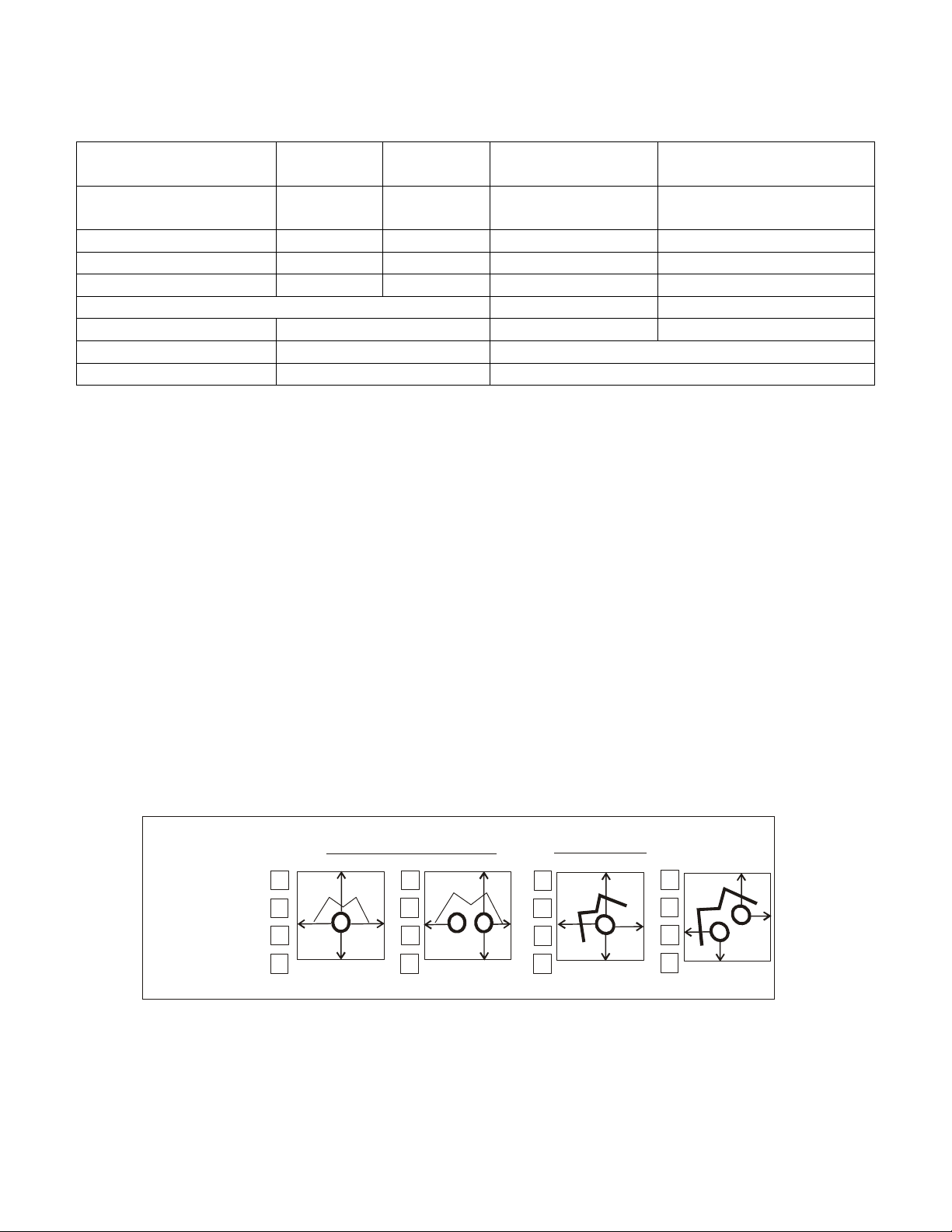
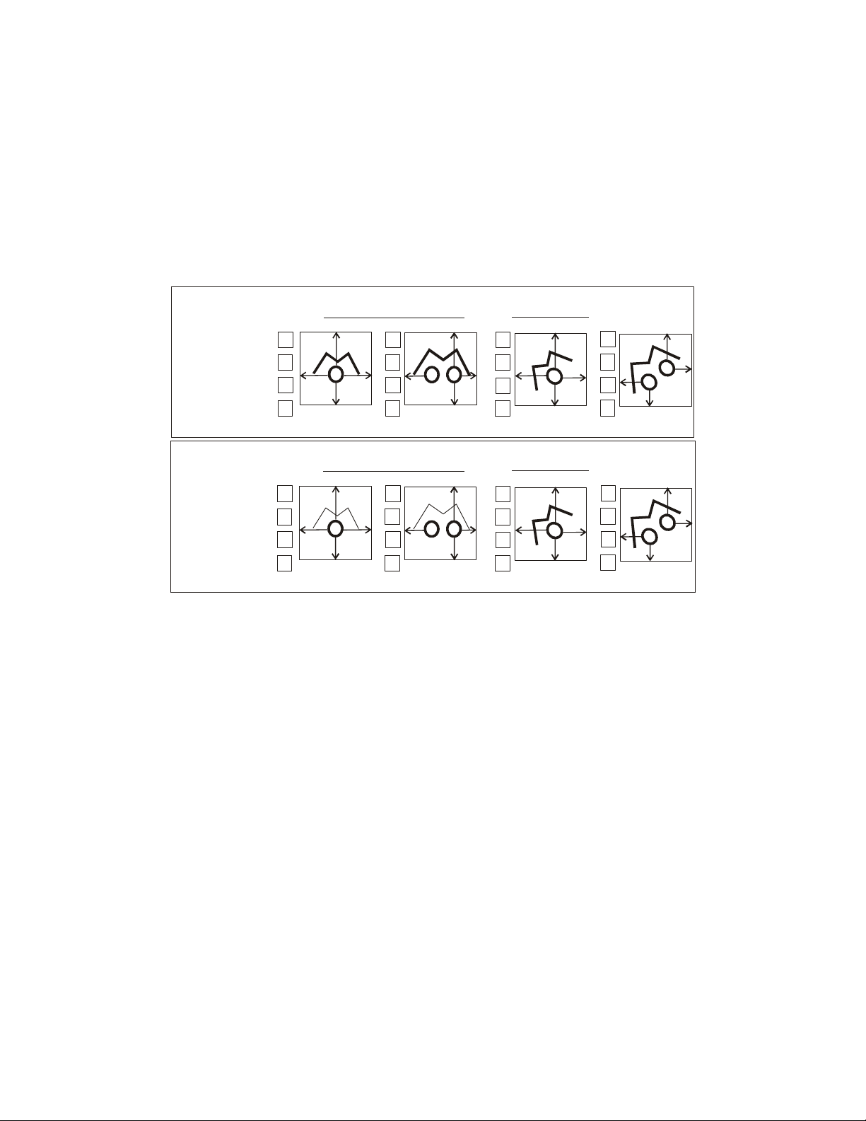
1. Suspend hanger with #10 Jack chain with strict adherence to specified placement
of hangers, see illustration on page 13. The first hanger must not be more than 6
inches from the burner flange. Hangers have 2 suspension rings. Use top ring if
reflectors are to be horizontal, or side ring if reflectors are to be angled.
2. With hangers installed, the primary tube can now be placed in the hangers.
Subsequent lengths of tube can now be installed, joining the lengths of tube
together and securing joints with the self-tapping screws provided. The self-
tapping screw holes must be adequately sealed during installation using a high
temperature sealant.
3. Reflector panels can now be placed in hanging supports. Sheet metal screws may
be used to secure reflectors together in pairs only.
4. With all radiant tubes and reflector panels now installed, the burner can be fitted
to the 2-flanged primary tubes using the bolted flange and nuts (provided). The
burner must be installed with the fan on the top. Burner employs a ring to
connect a hanging chain to stabilize the unit.
5. Heaters incorporating baffles must have the baffle installed at the immediate vent
end of the heater. This baffle is not to be installed in the primary tube.
U-SHAPED HEATER
1. U-Shaped heaters consist of radiant tubes, “U” bends, hangers, burner and
wide-angle reflectors.
2. Use #10 Jack chain to suspend the hangers from the ceiling, these hangers
must be spaced according to hanger location illustration.
3. With hangers now suspended, carefully lay the radiant tube in the holders,
flange section first.
4. Connect radiant tubes together using the self-tapping screws provided. The
self tapping screw holes must be adequately sealed during installation using a
high temperature sealant.
5. The 180 degree bend can now be fitted to the radiant tube and securely
tightened with self tapping screws provided on 180 degree bend.
6. Reflectors can now be placed in hangers.
7. Fit the burner to the flanged end of the tubes with bolts provided and connect
to the gas supply.
If the radiant tube has been supplied in 10ft. lengths, see diagram below for joining tubes
together.
Self tapping screws are provided to be installed into the expanded end of the radiant tube.
Slide the tubes together making sure that the first tube is inserted all the way into the
expanded end of the secondary tube.
Drill the self-tapping screws so as to secure the two tubes together.
Make sure to secure the tubes using the 3 screws provided as indicated in the drawing
below.

11
Subsequent secondary tubes can now be joined together in the same fashion.
The self-tapping screw holes must be adequately sealed during installation using a high
temperature sealant.
HANGER LOCATIONS

12
SUSPENDING THE SYSTEM
Inadequate or improper suspension of the tube heater can result in collapse of the system,
property damage, and personal injury or death. It is the installer’s responsibility to ensure that
the hardware and structural supports from which the heater is suspended are sound and of
adequate strength to support the weight and expansion forces of the heater.
Consider that the heater will expand in length as much as ½ inch (12.7) or more for every 10 ft (3
m) of system length. Typically, the greater the firing rate, the greater the expansion.
Survey the available structural supports, considering the system configuration and heat
requirements of the area to establish the optimum heater location. Locating a heater directly
under joists or beams, or installing supplemental steel support rail or angle iron can substantially
reduce labour and materials. Hardware with a minimum 60 lbs (27 kg) workload must be used at
each heater suspension point. Connect the structure using typical hardware as illustrated below or
by other mechanically sound means.
REFLECTOR EXTENSIONS
Reflector extensions may be installed on one side or both sides of the reflector. Reflector
extensions are 10 ft long x 9”. Drill 3 holes and insert S hooks.

13
GAS PIPING
1. All gas piping and connections shall be made in accordance with local codes and
CAN/CGA B-149 or ANSI standard Z223.1.
2. Connect the burner to gas supply with flexible gas connector.
3. A drip leg must be installed in the gas line at the heater inlet connection tee
followed by a pipe drop to the heater. Failure to provide a drip leg could result in
condensation and foreign matter passing into the gas valve. Failure to install a
drip leg in the gas line can cause property damage, injury or death and will void
the heater warranty.

14
CAUTION: Correct inlet pressure is vital to efficient operation of heaters. Refer to
the rating plate and, if necessary, consult Gas Company.
Warning
Never use a match or other flame to test for gas leaks. Use soap and water solution to
check for leaks to all connections and joints and if bubbles appear, leaks have been
detected and must be corrected. Never operate the heater with leaking connections.
The supply system should be checked first with heater turned off followed by another
check with the heater on. The supply gas pressure must be checked with all heaters in
operation.
GAS SUPPLY, HEATER EXPANSION, AND FLEXIBLE GAS
CONNECTION
The gas supply must be installed to the heater using:
In USA an approved Stainless Steel Flexible Gas Connector certified for use on an
infrared radiant tube heater (ANSI Z21.24 CSA 6.10)
In Canada an approved Type 1 Hose Gas Connector (CAN/CGA 8.1)
The heater must be isolated from the gas supply piping system by closing its
individual manual shut off valve (field supplied) during any pressure testing of the
gas supply piping system.
Compensation for normal gas supply pipe expansion, and radiant tube heater
expansion must be provided. All piping must conform to local codes.
Provide a 1/8 in (3.2mm) NPT plugged tapping, accessible for test gauge connection,
immediately upstream of the gas supply connection to the heater.
Test for leaks. All gas piping and connections must be tested for leaks after the
installation is completed.
Apply soapsuds solution to all connections and joints and if bubbles appear, leaks
have been detected and must be corrected. Do not use a match or open flame of any
kind to test for leaks. Never operate the heater with leaking connections.
The supply systems should be checked first with the heater turned off followed by
another check with the heater turned on. The supply gas pressure must be checked
with all heaters in operation.

15
VENTING
1. The Easy Radiant tube system has been approved for vented and un-vented
applications. When installed un-vented it must be electrically interlocked to an
exhaust fan with an air proving switch. The exhaust fan must provide exhaust in
the amount of 300 c.f.m. for every 100,000 BTU input in Canada and the amount
of 400 c.f.m. for every 100,000 BTU input in the USA. When installed un-vented
provision must be made to supply adequate combustion air from outside the
space. Combustion air openings must be in the amount of one (1) square inch or
more of free area for each 10,000 BTUH. When installed vented, installations
must comply with all governing codes.
2. When installed in a large and adequately ventilated space (agricultural building
used only for brooding purposes) the heater may be installed un-vented without
interlocking, and may be operated by discharging the combustion products
directly into the space, subject to the approval of the authority having jurisdiction
and provided that the maximum input of the appliance does not exceed 20
BTUH/ft3(0.2 kW/m3) of the space in which the heater is located. An appliance
designed to produce a controlled atmosphere need not be subject to these
conditions.
3. All venting material shall be CGA/AGA approved and minimum 4” diameter.
4. The maximum allowable length of vent pipe is 60 feet. This length includes the
combination of inlet air vent for combustion and exhaust venting. THE
RADIANT TUBE IS NOT INCLUDED IN THE MEASUREMENT. For every
90-degree bend in the system, 5 feet must be deducted from the total.
5. When venting through a combustible wall or roof, type “B” vent must be used for
that portion of the vent that passed through the wall or roof. For wall venting, the
manufacturer’s approved vent spout or exhaust cap must be used. See page 20.
All models vented through a side wall to be connected to a 4” diameter type “B”
or “L” vent. The maximum equivalent vent length is 30 ft. For each 90 degree
elbow 5 ft must be deducted from the equivalent maximum. The use of any wall
vent terminal other than that supplied by EASY RADIANT will void
warranties. EASY RADIANT WORKS accepts no responsibility for damages
created by other vent terminals. Exceeding the allowable lengths noted may
create condensation problems and will void Design Certification and the heater
warranty.
6. All vent pipe used with a slip fit connection must be mechanically secured, and all
vents must be supported every 3 feet.
7. Vent pipe of single wall construction shall not run through unheated spaces unless
insulated.
8. All vent pipes longer than 10 feet must be insulated or have insulated type vent
materials.
9. Vents for products of combustion shall not terminate less than three (3) feet from
a combustion air inlet of any other appliance, or be less than three (3) feet from a
building opening or be directly above a gas utility meter or service regulator.
10. The exhaust vent terminal must be installed not less than 7 feet above grade.
11. Air intakes terminals shall not be located less than three (3) feet above grade.
NOTE:When located in a building with a negative air condition, or in a dusty or
dirty atmosphere such as a wood working shop, poultry barn or foundries,
combustion air from outside the negative or dirty area to the burner is mandatory.
The combustion air supply should be minimum 4-inch diameter seamless air duct,
connected to fresh air adapter provided on combustion air blower. All joints or
seams shall be sealed to prevent leaks.

16
12. Horizontal vent systems shall slope downwards not less than ¼” per foot from the
start of the vent system to the vent terminal.
Two units may be exhausted on a common 6” vent with the use of the AC1120
4” x 4” x 6” exhaust T, for both side wall and roof venting. A suitably rated and
certified high temperature exhaust cap must be used on the end of the 6” exhaust
vent. Units with common exhaust must be jointly controlled. The addition of the
AC1120 exhaust T introduces a 90’ degree bend into the venting of each unit,
deducting 5’ (1.5m) from the allowable total of exhaust/intake venting for each
unit.
WARNING
This heater will expand in length as it heats up. It is a normal condition that during
heat-up and cool-down a tube heater will expand and contract. Allowances for heater
expansion must be made in the gas connection, venting and combustion air ducting.
Improper installation, alteration, or adjustment can result in property damage, injury
or death.
The BTU input and the tube length determine the overall expansion that occurs. A
typical infrared tube installation will expand toward both the burner and the vent end.
To allow heater expansion the gas supply must be installed using:
In the USA: a stainless steel flexible gas connector certified for use on an infrared
radiant tube heater (ANSI Z21.24 CSA 6.10)
In Canada: a Type 1 hose connector (CAN/CGA 8.1). Also the flue vent, and
combustion air intake (if used) must be installed in such a manner that the normal
expansion of the heater will be accommodated.

17
VENTING OPTIONS

18
LISTED ACCESSORIES:
AC1010 Ind. Thermostat 120V
AC1020 Agricultural Thermostat
AC1030 Remote Thermostat
AC1050 Agricultural Thermostat
AC1060 24V Thermostat
AC1070 Flexible Gas Connector
AC1080 Outside Air Adapter
AC1030 Remote Thermostat
AC1100 Outside Air Wall Cap
AC1110 Combustion Air Flex Duct
AC1120 4x4x6 Tee
AC1130 90 degree Elbow
AC1140 180 degree Bend
AC1150 Wall Thimble
AC1170 Brooder Exhaust Cap 4" dia
AC1180 4” Wall Spout Exhaust Cap
AC1200 24V Thermostat
AC1220 Fresh Air Package (Cap, Duct, Clamps)
AC1350 Reflector Supports
AC1085 Attic Air Intake with adapter

19

20
This manual suits for next models
9
Table of contents
Other Easy Radiant Works Heater manuals
Popular Heater manuals by other brands

T.B.D.
T.B.D. HEATOR SRE 804 TC - datasheet

Toyotomi
Toyotomi LC-44 instruction manual

Elnur
Elnur INTERTIARX4P Installation instructions and user guide

L.B. White
L.B. White Premier TS080 Owner's manual and instructions

Cantherm
Cantherm PHOEN 400 instruction manual

Dimplex
Dimplex PCH1000TCW installation instructions