1
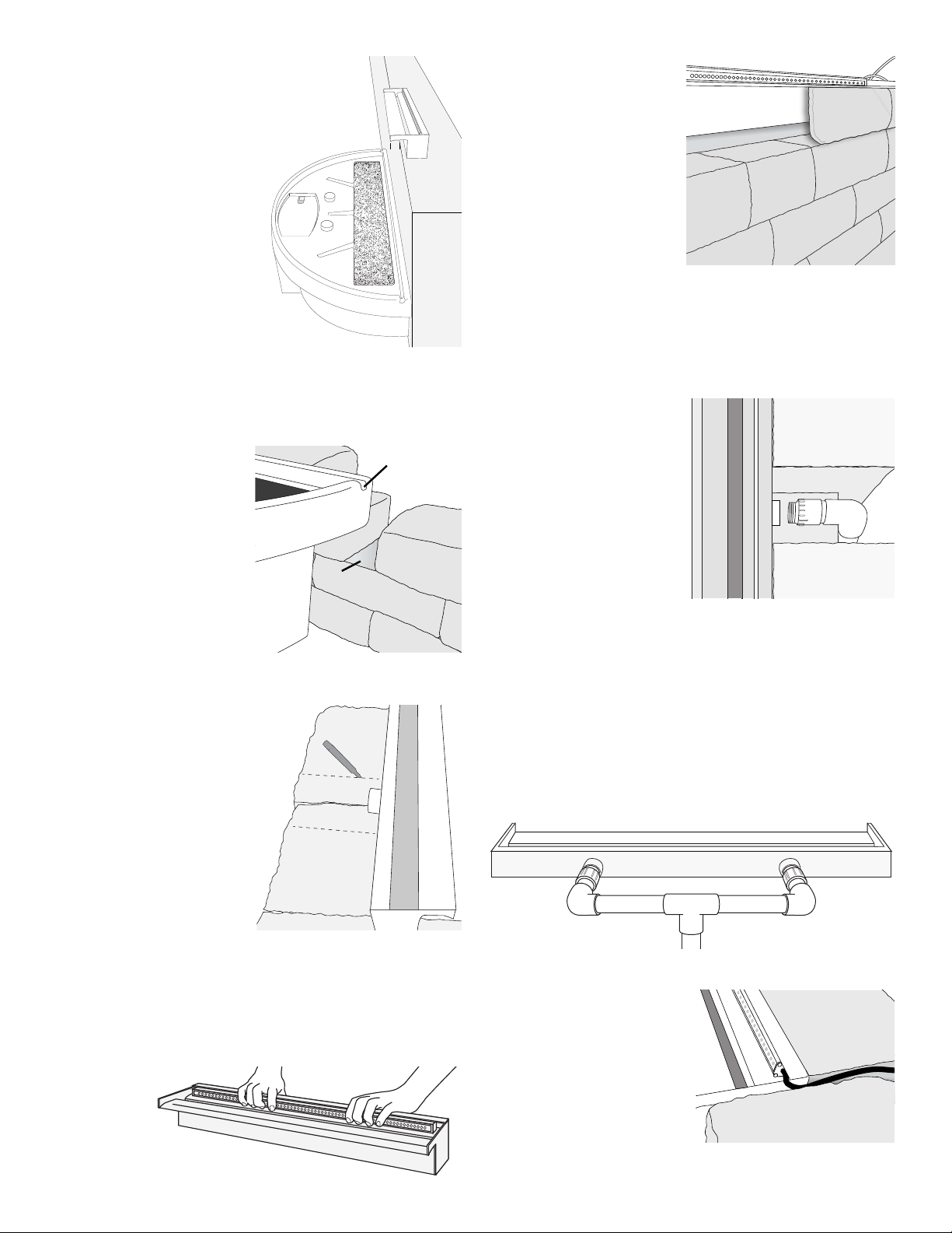
Determine the placement
of the Vianti Falls system.
Prepare the base for the
48" half basin by properly
compacting and leveling the
area. The Vianti Falls spillway
is designed to be placed
approximately 12" to 30"
above the basin. The center
of the spillway and the basin
must be aligned. The spillway
must be positioned in the wall
to allow for the lip to protrude
past the wall 11/4" (assuming
the wall is plumb). This is to
ensure water will land in the 6"
x 39" splash mat included with the basin. Extended lip kits
come with 14" x 39" additional splash mat to be installed
on top of basin (see page one).
Splash
Mat
1
1
/
4
"
2
When building the
block wall, a section
of wall must be left out to
accommodate the plumbing
and electrical cord for the
pump. The notch in the back
of the basin is for the power
cord of the pump. If an auto
ll line is being installed a
section of wall should also
be open to accommodate
the auto ll feed line.
Power
Cord
Notch
Holefor
Plumbing
andPump
PowerCord
3
Once the spillway
placement has been
determined in the block wall,
the block will need to be cut
to allow for the plumbing
connections on the back of
the spillway. Use appropriate
tools and extreme care when
cutting block. Consult block
manufacturer recommendations
for properly cutting block
being used.
4
If the lighting option is purchased the LED light strip
can be tted into the back of the spillway. There are
brackets on the ends of the light bars with holes in them.
These brackets are for other applications. The LED light
bar should t snuggly into the back of the spillway.
If necessary, a small amount of silicone can be used as an
adhesive to
hold the bar
in place.
5
Depending on the look
desired, the block that
goes around the spillway
may need to be cut to
ensure proper leveling and
look of the spillway in the
wall. The type of block
being used will determine
the method used. A lentil
may be required for longer
spillways or in walls that
would require additional
weight bearing support. Consult a qualied professional
for specic installation requirements and codes.
The spillway should be “dry t” to ensure the spillway is
level from side to side and front to back.
6
Once the spillway is
level and “dry t” the
plumbing can now be
tted. Use the1" PVC male
adaptor and the ttings
provided to connect
spillway to the exible PVC
pipe. Wrap the threads
of the PVC male adaptor
with Teon tape and thread
into the spillway inlet(s).
Determine the placement of additional ttings (elbows,
tees, and extra pipe). Cut and glue all the pieces together
to t the application.
7
The dual inlet units can be supplied with one mainline.
Picture is for illustration only. Application may vary
from image shown. After the mainline is split into two, the
plumbing lengths to the spillway inlets should be equal.
This will ensure equal ow rates to both inlets, while being
able to control the overall ow with a single ball valve.
8
The cord for the LED light
strip can be tucked into
the notch in the spillway.
A dab of silicone should be
used to seal the notch on
opposing side. Tuck the cord
between the blocks to run
the cord to the power source.
Ideally, run cord through
conduit for future maintenance or removal of light strip.