manuals.online logo
Brands
  1. Home
  2. •
  3. Brands
  4. •
  5. Eaton
  6. •
  7. Accessories
  8. •
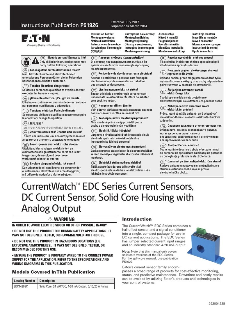
  9. Eaton IntelliView E76 Series Manual

Eaton IntelliView E76 Series Manual

Electric current! Danger to life!
Only skilled or instructed persons may
carry out the following operations.
Lebensgefahr durch elektrischen Strom!
Nur Elektrofachkräfte und elektrotechnisch
unterwiesene Personen dürfen die im Folgenden
beschriebenen Arbeiten ausführen.
Tension électrique dangereuse !
Seules les personnes qualifiées et averties doivent
exécuter les travaux ci-après.
¡Corriente eléctrica! ¡Peligro de muerte!
El trabajo a continuación descrito debe ser realizado
por personas cualificadas y advertidas.
Tensione elettrica: Pericolo di morte!
Solo persone abilitate e qualificate possono eseguire
le operazioni di seguito riportate.
触触电电危危险险!!
只允许专业人员和受过专业训练的人员进行
下列工作。
Электрический ток! Опасно для жизни!
Только специалисты или проинструктированные
лица могут выполнять следующие операции.
تتﻮﻮــــﻣﻣﺮﺮــــﻄﻄﺧﺧ!!ﻲﻲﺋﺋﺎﺎــــﺑﺑﺮﺮﻬﻬﻛﻛررﺎﺎــــﻴﻴﺗﺗ!!ﺮﺮﻳﻳﺬﺬــــﺤﺤﺗﺗ!!
ﺐـــــﻴﻛﺮﺘﻟا و ﺔﻧﺎﻴـــــﺼﻟا لﺎـــــﻤﻋا ﻢـــــﺘﺗ ﻻ
ﻦﻴﺑرﺪــــﻤﻟا ﻦﻴﻠﻣﺎــــﻌﻟا ﻞــــﺒﻗ ﻦــــﻣ ﻻا !
en
de
fr
es
it
zh
ru
ar
03/22 IL05305009Z (P52078)
Instruction Leaflet
Montageanweisung
Notice d’installation
Instrucciones de montaje
Istruzioni per il montaggio
安
安装装说说明明
Инструкция по монтажу
تتﺎﺎــــــــــﻤﻤﻴﻴﻠﻠﻌﻌﺘﺘﻟﻟااررﻮﻮــــــــــﺸﺸﻨﻨﻣﻣ
1/4
Instruction Leaflet IL05305009Z (P52078) Effective March 2022
Supersedes May 2018 E76 Series
IntelliView Series Color measuring
Optical Sensors
E76…
Dimensions
aConnector can rotate 90 or 180 degrees to accept different sensor mounting orientations.
11 mm
(0.43") 14 mm
(0.55")
15 mm
(0.59")
M12
25 mm
(0.99")
16 mm
(0.63") 31.7 mm
(1.25")
2 mm
(0.08")
18 mm x 45º
(0.71" x 45º)
42 mm
(1.65")
42 mm
(1.65")
50 mm (1.97")
50 mm (1.97")
SELSET
5.5 mm
(0.22")
20 mm
(0.79") 17.1 mm
(0.67")
7.8 mm
(0.31")
①
2/4
03/22 IL05305009Z (P52078)
Wiring diagrams
Detection diagram
Controls and adjustment
NPN PNP
RS 485
aDetectable Colors
bWhite/Light yellow
cDark blue/Black
Yellow LED When the yellow LED is on, this indicates the OR function of the three OUT1, OUT2 and OUT3 outputs.
Green 4-Digit Display The display indicates the “run” or “rund” (run with delay) operating mode (→ Initial Setup).
OUT1, OUT2, OUT3 LEDs
Indicates the corresponding output is active.
SET Button Activates the simple setup procedure (→ Initial Setup).
SEL Button This button allows you to scroll through sensor settings (→ Initial Setup).
Tecla SEL Esta tecla permite hojear por los ajustes de los sensores (→ primera instalación).
4
3
56
87
1
2
0 V (BU)
+V +V (BN)
SYNC INPUT
(RD)
OUTPUT #1OUTPUT #2
0 V
OUTPUT #3
(GN)(YE)(GY)
Load Load Load
4
3
56
87
1
2
0 V (BU)
+V +V (BN)
SYNC INPUT
(RD)
OUTPUT #1OUTPUT #2
0 V OUTPUT #3
Load Load Load
(GY)(YE)(GN)
4
3
56
87
1
2
0 V (BU)
+V +V (BN)
Rx/Tx (WH)
SYNC INPUT
(RD)
OUTPUT #1OUTPUT #2
0 V
OUTPUT #3
(GN)(YE)(GY)
Load Load Load
(BU)
Rx/Tx (PK)
→DIN IEC 304, DIN IEC 757
BN 1
BU 6
GN 5
GY 8
PK 22
RD 2
WH 9
YE 4
20 30 35105 150 40 4525 50
0
90
81
72
63
54
45
36
27
18
9
[mm]
[%]
①
②
③
3/4
03/22 IL05305009Z (P52078)
Initial Setup Setting parameters
The three-phase sensor setting allows the adjustment of channel,
operating mode and tolerance values.
● = Button pressed ○ = Button not pressed
■ = LED on □ = LED o
Detection
– Place object to detect inside the operating distance, in front of the sensor.
– Press the SET button for at least two seconds.
– The “Set1” message is visualized.
Channel Setting
– Use the SEL button to select the channel of detection.
Operating mode
– Place the SET button again to confi gure operating mode.
– Select C (color) or C+I (color + intensity) using the SEL button.
–Note: The “C” type algorithm is used to obtain a larger depth of field, or to
detect colors on different opaque, shiny or reflecting surfaces. Whereas the
“C+I” type algorithm offers a higher sensitivity toward tone variations and is
recommended for the detection of different colors on the same type of
material, with the possibility of also distinguishing the gray tones.
Teach and Tolerance Settings
– Press the SET button again, the “updt” text blinks for two seconds.
– The sensor then automatically passes into the tolerance section.
– Use the SEL button to select the required value.
– The “FAIL” text alternated with “Hi” or “Lo” is visualized
if the detection is not correct.
– Repeat the procedure starting from the Operating Mode.
Delay Value Visualizing and Setting
– Press the SET button for at least six seconds to access the delay setting mode.
Notes on Setting Delay
At each press of the SET button, the different delay levels in milliseconds are
shown in a cyclical manner, and the delay value will be stored. The delay value
setting is common for all three outputs. When a delay value other than zero is set,
the outputs will be maintained active for a minimum time equal to the number of
milliseconds visualized on the display
(i.e. d-00 = 0 ms, d-05 = 5 ms, d-10 = 10 ms).
Channel Status Visualization
This function provides adjustment for all three sensor channels.
Press the SEL button for at least two seconds and channel, operating mode and
tolerance are shown sequentially.
– At the end of the sequence, the display will indicate the “run” or “rund”
operating mode again.
Non-Initializing E2PROM
If the display indicates “E2Pr” the sensor does not have any of the three channels
initialized.
– In this case, it is sufficient to program one single channel to obtain the “run”
or “rund” visualization on the display.
OUT Display Keyboard
OR 1 2 3 Dig1 Dig2 Dig3 Dig4 SET SEL
r u n d
OR 1 2 3 Dig1 Dig2 Dig3 Dig4 SET SEL
S E t 1
OR 1 2 3 Dig1 Dig2 Dig3 Dig4 SET SEL
S E t 1
S E t 2
S E t 3
OR 1 2 3 Dig1 Dig2 Dig3 Dig4 SET SEL
C
C _ I
OUT Display Keyboard
OR 1 2 3 Dig1 Dig2 Dig3 Dig4 SET SEL
u p d t
OR 1 2 3 Dig1 Dig2 Dig3 Dig4 SET SEL
t o L 0
t o L 1
t o L 2
t o L …
t o L 9
→The 0, 1 and 2 tolerance values are particularly suitable for
critical applications.
OUT Display Keyboard
OR 1 2 3 Dig1 Dig2 Dig3 Dig4 SET SEL
r u n d
OR 1 2 3 Dig1 Dig2 Dig3 Dig4 SET SEL
d - 0 0
d - 0 5
d - 1 0
d - 2 0
d - 3 0
d - 4 0
OUT Display Keyboard
OR 1 2 3 Dig1 Dig2 Dig3 Dig4 SET SEL
r u n d
OR 1 2 3 Dig1 Dig2 Dig3 Dig4 SET SEL
C h _ 1
C _ I
t o L 2
C h _ 2
C
t o L 1
C h _ 3
C
t o L 8
d - 0 5
OR 1 2 3 Dig1 Dig2 Dig3 Dig4 SET SEL
r u n d
OUT Display Keyboard
OR 1 2 3 Dig1 Dig2 Dig3 Dig4 SET SEL
E 2 P r
03/22 IL05305009Z (P52078)
USA:
Eaton.com/eatoncare
+1 877-386-2273
Eaton.com/sensors
+1 800-426-9184
Eaton.com/contacts
Eaton.com/aftersales
Eaton.com/documentation
USA: Eaton Corporation, W126 N7250 Flint Drive, Menomonee Falls, WI 53051, USA Publication No.
IL05305009Z (P52078) March 2022
EU: Eaton Industries GmbH, Hein-Moeller-Straße 7-11, 53115 Bonn, Germany
UK: Eaton Electric Ltd., P.O. Box 554, Abbey Park, Southampton Road, Titchfield, PO14 4QA, UK
Eaton.com/recycling
4/4 © 2012 Eaton Corporation
Eaton is a registered trademark of Eaton Corporation. All other trademarks are property of their respective owners.
Remote Functions
KEYLOCK Function (SET Button Block)
If during sensor power-up the SYNC wire is connected to +V DC for at least one second, the keylock function will be activated and buttons will no longer be active.
After the first second, the SYNC input is available for the normal operating modes.
To deactivate the keylock, the sensor has to be turned off and re-powered with the SYNC wire not connected or ground connected (GND).
SYNC Input
The status of the SYNC input can determine the beginning and end of color identification. The sensor operates normally with all outputs functional with the
SYNC input disconnected (or connected to 0 V). When you connect +24 V to the SYNC input, the sensor outputs are disabled and color sensing stops (after the time
delay shown in the drawing at left). This may be useful with a multi-colored target where the color to detect is in a specific position, while other zones should be ignored.
RS485 Serial Connection (Only For E75-CLRMKRS-M12)
Complete sensor remote control is possible using the RS485 line. All functions, such as channel, tolerance and operating mode selection, can be accessed via
the serial connection. The serial communication parameters are as follows: 9600 baud, no equity, 8 data bits, 1 stop bit. All commands have to be sent via terminal
in an ASCII format as follows:
Received Channel Status
At any moment, the receipt of the ‘r <CR> <LF>’ command indicates the sensor configuration.
Remote Setting Mode
To access the remote setting mode, the SYNC input must remain passive for at least 300 ms. The commands available are:
@ <CR> <LF> Beginning of the remote setting (together with passive SYNC)
cx <CR> <LF> Channel selection, with x {1,2,3}
tx <CR> <LF> Tolerance selection, with x {0,1,2,3,4,5,6,7,8,9}
mx <CR> <LF> Operating mode selection, with x {1,2}
m1 = C
m2 = C+1
e <CR> <LF> Configuration sequence activation
q <CR> <LF> Exit from remote setting mode without saving configuration
If the SYNC input is activated before the ‘e’ (execute) command is given, the sensor exits the remote setting mode without saving the configuration,
similar to the ‘q’ (quit) command.
If the SYNC input is active at the receipt of the ‘@ <CR> <LF>’ command, the sensor responds with: ‘?? <CR> <LF>.’
At the receipt of the ‘q <CR> <LF>’ or ‘e <CR> <LF>’ commands, the sensor transmits ‘ok <CR> <LF>.’
The ‘lo <CR> <LF>’ message is transmitted if the signal is too low and ‘hi <CR> <LF>’ if the signal is too high.
Delay Configuration
To access the delay configuration, the SYNC input has to remain passive for at least 300 ms. The commands available are:
@ <CR> <LF> Beginning of the delay configuration (together with passive SYNC)
dx <CR> <LF> Delay selection, with x {0,1,2,3,4,5}
d0 = 0 ms d3 = 20 ms
d1 = 5 ms d4 = 30 ms
d2 = 10 ms d5 = 40 ms
e <CR> <LF> Memorization of the new delay
q <CR> <LF> Exit from the delay configuration without saving
If the SYNC input is active at the receipt of the ‘@ <CR> <LF>’ command, the sensor responds with: ‘?? <CR> <LF>.’
At the receipt of the ‘q <CR> <LF>’ or ‘e <CR> <LF>’ commands, the sensor transmits: ‘ok <CR> <LF>.’
SYNC
24 V
Output Disable signal
0 V (or Open)
Output Enable signal
OUTPUT
ON
OFF
≦335 μs≦170 μs
→During the command transmission, single strings have to follow each other with a delay of at least 1 ms.
Other Eaton Accessories manuals

Eaton Crouse-hinds series User manual

Eaton

Eaton Crouse-hinds series User manual

Eaton OSP10M User manual

Eaton

Eaton OSP10M User manual

Eaton Crouse-Hinds IF 1744 Setup guide

Eaton

Eaton Crouse-Hinds IF 1744 Setup guide

Eaton E56M Manual

Eaton

Eaton E56M Manual

Eaton E67 Series Manual

Eaton

Eaton E67 Series Manual

Eaton Comet Series Manual

Eaton

Eaton Comet Series Manual

Eaton iProx Series Instruction manual

Eaton

Eaton iProx Series Instruction manual

Eaton EAFR-01 User manual

Eaton

Eaton EAFR-01 User manual

Eaton CEMU-01/03 User manual

Eaton

Eaton CEMU-01/03 User manual

Eaton xComfort CTEU-02/0 Series User manual

Eaton

Eaton xComfort CTEU-02/0 Series User manual

Eaton NanoView E71 Series Manual

Eaton

Eaton NanoView E71 Series Manual

Eaton Evolution 650 User manual

Eaton

Eaton Evolution 650 User manual

Eaton Powerware Series User manual

Eaton

Eaton Powerware Series User manual

Eaton Home Heartbeat User manual

Eaton

Eaton Home Heartbeat User manual

Eaton E57P Series Manual

Eaton

Eaton E57P Series Manual

Eaton Metalux User manual

Eaton

Eaton Metalux User manual

Eaton CurrentWatch EGFL Series Manual

Eaton

Eaton CurrentWatch EGFL Series Manual

Eaton CurrentWatch EDC Series Manual

Eaton

Eaton CurrentWatch EDC Series Manual

Eaton CurrentWatch EPRM Series User manual

Eaton

Eaton CurrentWatch EPRM Series User manual

Eaton MPD-C-EXT User manual

Eaton

Eaton MPD-C-EXT User manual

Eaton Crouse-hinds series User manual

Eaton

Eaton Crouse-hinds series User manual

Eaton CurrentWatch EGFL Series Manual

Eaton

Eaton CurrentWatch EGFL Series Manual

Eaton CurrentWatch EAC Series User manual

Eaton

Eaton CurrentWatch EAC Series User manual

Eaton GridAdvisor II Series User manual

Eaton

Eaton GridAdvisor II Series User manual

Popular Accessories manuals by other brands

Vivotek AI-103 installation guide

Vivotek

Vivotek AI-103 installation guide

Rohde & Schwarz ND 951 Installation and commissioning

Rohde & Schwarz

Rohde & Schwarz ND 951 Installation and commissioning

HoMedics UV Clean SANITIZER CASE Instruction manual and  warranty information

HoMedics

HoMedics UV Clean SANITIZER CASE Instruction manual and warranty information

poly-planar MRD-60 Specifications

poly-planar

poly-planar MRD-60 Specifications

Geerpres UVAIRO 600 Service manual

Geerpres

Geerpres UVAIRO 600 Service manual

Bellman BE9250 manual

Bellman

Bellman BE9250 manual

Gardena 1188 operating instructions

Gardena

Gardena 1188 operating instructions

PCB Piezotronics ICP 137B21B Installation and operating manual

PCB Piezotronics

PCB Piezotronics ICP 137B21B Installation and operating manual

Dini Argeo 3590EKR Series Technical manual

Dini Argeo

Dini Argeo 3590EKR Series Technical manual

BeeSecure BEE-DWS user manual

BeeSecure

BeeSecure BEE-DWS user manual

PCB Piezotronics 221B01 Installation and operating manual

PCB Piezotronics

PCB Piezotronics 221B01 Installation and operating manual

Julabo 950002503P3H0 operating manual

Julabo

Julabo 950002503P3H0 operating manual

Axor Carlton Toilet Paper Holder 41438XX1 Specification sheet

Axor

Axor Carlton Toilet Paper Holder 41438XX1 Specification sheet

JK Audio InlinePatch user guide

JK Audio

JK Audio InlinePatch user guide

EVA Logik ZW97 quick start guide

EVA Logik

EVA Logik ZW97 quick start guide

Daktronics BA-2009 DISPLAY MANUAL

Daktronics

Daktronics BA-2009 DISPLAY MANUAL

Integrated Visual Data Technology Inc. SkidWeigh ED2E-EP Series Installation & Calibration Manual

Integrated Visual Data Technology Inc.

Integrated Visual Data Technology Inc. SkidWeigh ED2E-EP Series Installation & Calibration Manual

Hydac MCS 13 series Operation and installation guide

Hydac

Hydac MCS 13 series Operation and installation guide

manuals.online logo
manuals.online logoBrands
  • About & Mission
  • Contact us
  • Privacy Policy
  • Terms and Conditions

Copyright 2025 Manuals.Online. All Rights Reserved.