manuals.online logo
Brands
  1. Home
  2. •
  3. Brands
  4. •
  5. Eaton
  6. •
  7. Accessories
  8. •
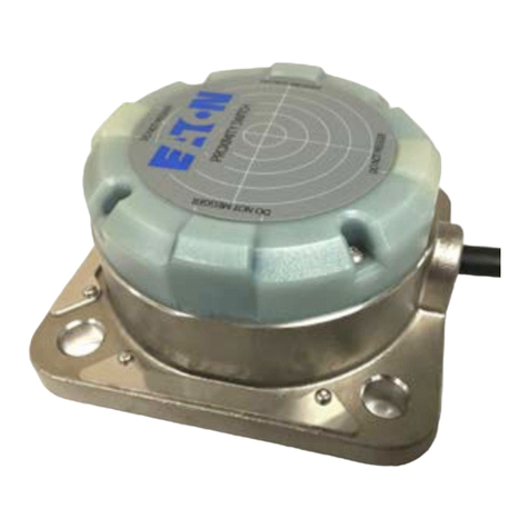
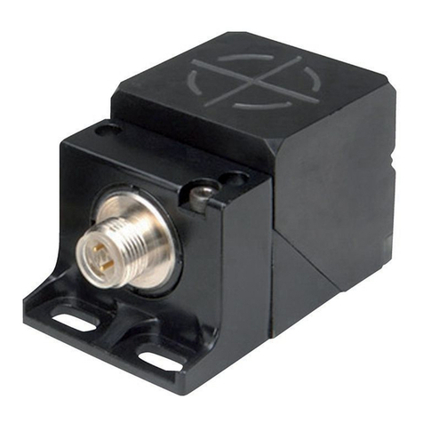
  9. Eaton iProx Series Instruction manual

Eaton iProx Series Instruction manual

Effective June 2013
Supersedes October 2005
Technical Data TD05301003E
iProx inductive proximity sensors—
optimizing hysteresis
Description
The iProx姠family of inductive sensors features extremely
high sensing performance. Like many sensors, the various
operating characteristics, such as range, hysteresis, and
output, have been preset from the factory to be ideal for
a wide variety of sensing applications. Where iProx differs
from other sensors is in the ease of changing these default
operating characteristics to suit specific applications. This
document will cover hysteresis—what it is, the benefits of
modifying it, and how to change it.
Hysteresis and why it is important
All sensing devices incorporate some level of hysteresis.
Hysteresis is the difference between the signal levels at
which a sensor turns off and turns on. This difference can
usually be observed by slowly bringing a target toward the
sensor until it turns on and then moving it away until it turns
off. The point where the sensor turns on will be slightly closer
to the sensor than the point it turns off (see Figure 1).
Sensor
Sensor
Turn-On Point
Turn-Off Point
Hysteresis
Figure 1. Hysteresis in Presence Sensing
This difference, usually in the area of 10% to 15%, is
necessary to reduce the sensor’s sensitivity to noise and
vibration. It also eliminates multiple transitions (called
“chattering”) at the point where the output switches.
A mechanical version of this effect can be found in many
electrical switches. For instance, as you move the handle
just past the center point, a spring in the switch will pull the
handle all the way over, ensuring that the switch ends up in
a definite ON or OFF state.
When it is necessary to adjust hysteresis
As stated before, the factory preset hysteresis setting is
appropriate for most sensing applications. But for some, the
ability to fine-tune the sensor hysteresis setting will greatly
increase reliability. For others, it may be the only way to solve
the application.
For sensing applications that occur in areas of high shock
or vibration, a wider hysteresis setting may be necessary to
ensure reliable machine operation (see Figure 2).
Sensor
Factory Preset Hysteresis
Heavily Vibrating Target
Exceeds Standard Hysteresis
Limits and Causes Unreliable
Sensor Operation
Wider Hysteresis Setting to
Accommodate Unintentional
Target Movement
Figure 2. An Example Requiring Increased
Sensor Hysteresis
By increasing the hysteresis, you can accommodate
unintentional movement of the target due to shock or
vibration without causing multiple output signals during
one sensing event.
When widening the hysteresis, it is important to ensure
that the normal travel of the target will take it far enough in
both extremes to ensure reliable turn-on and turn-off events
(see Figure 3).
Wider Hysteresis
Setting
Vibrating Target
Target Must Travel
Far Enough in Both
Directions to Ensure
Reliable Turn-On and
Turn-Off Events
Sensor
Sensor
Figure 3. Target Travel Considerations With
Increased Hysteresis
On the other end of the spectrum, you may have an
extremely precise and stable application where you need
highly accurate results. In this case, setting the hysteresis
to a tighter setting than the factory preset will provide this
high accuracy.
Technical Data TD05301003E
Effective June 2013
iProx inductive proximity sensors—
optimizing hysteresis
Eaton is a registered trademark.
All other trademarks are property
of their respective owners.
Eaton
1000 Eaton Boulevard
Cleveland, OH 44122
United States
Eaton.com
© 2013 Eaton
All Rights Reserved
Printed in USA
Publication No. TD05301003E / Z13431
June 2013
Setting iProx hysteresis
To adjust the hysteresis on the iProx sensor, follow the procedure
listed below. For more detailed instructions on adjusting hysteresis
with the software, consult the iProx Programming Software User
Guide (P50228) included on the software CD-ROM.
1. Connect the programming device to your computer. Connect
the remote programmer (E59RP1) to your computer’s serial or
USB port.
2. Launch the iProx Programming Software from the Start menu.
3. Affix the magnetic puck to the face of the sensor. To ensure
proper mounting, it may be necessary to remove the mounting
nuts from the sensor.
4. Ensure that the sensor(s) you intend to program are powered on.
5. The iProx Programming Software should automatically detect the
sensor(s). See the “Connection Status” information displayed
at the bottom of the “Getting Started” window to confirm
the software has detected the sensor(s). If the software does
not detect the connected sensor(s), you may need to select
a wider COM port range in the software settings. For more
troubleshooting information, consult the iProx Programming
Software User Guide (P50228) by clicking on the “Help”
window and selecting “Contents/FAQs.”
6. From the “Getting Started” window, select “Configure iProx”
to modify the parameters of your iProx sensor.
7. Under “Step 1: Select Sensor to Modify,” click the drop-down
menu and select the sensor that you intend to modify. It may
take a few seconds to communicate with the sensor. Once this
is complete, the rest of the screen should become enabled,
allowing you to modify the parameters of the selected sensor.
8. The “Modify Sensing Range” section at the bottom of the
window displays operate and release points as well as a graphic
depiction of the sensing attributes. The “Operate Point” is the
distance at which an incoming target is first detected. The
“Release Point” is the point at which the target is beyond the
detection range of the sensor. The difference between these
two points is the hysteresis. To add hysteresis, simply widen
the distance between the operate point and release point
(by reducing the operate point or increasing the release point).
Notice that the sensing range graphic will dynamically change as
you modify the hysteresis. Conversely, to reduce hysteresis, just
decrease the distance between the two points (by increasing
the operate point or decreasing the release point).
9. When you are satisfied with your changes, click the “Program”
button at the bottom of the screen. Repeat this process for each
iProx sensor.

This manual suits for next models

1

Other Eaton Accessories manuals

Eaton Crouse-hinds series User manual

Eaton

Eaton Crouse-hinds series User manual

Eaton E67 Series Manual

Eaton

Eaton E67 Series Manual

Eaton Crouse-Hinds GHG 515 User manual

Eaton

Eaton Crouse-Hinds GHG 515 User manual

Eaton CurrentWatch EGFL Series Manual

Eaton

Eaton CurrentWatch EGFL Series Manual

Eaton NanoView E71 Series Manual

Eaton

Eaton NanoView E71 Series Manual

Eaton Powerware Series User manual

Eaton

Eaton Powerware Series User manual

Eaton ALL-PRO MSS1301LW User manual

Eaton

Eaton ALL-PRO MSS1301LW User manual

Eaton CurrentWatch EPRM Series User manual

Eaton

Eaton CurrentWatch EPRM Series User manual

Eaton E58 Series Manual

Eaton

Eaton E58 Series Manual

Eaton GFX User manual

Eaton

Eaton GFX User manual

Eaton OSP10M User manual

Eaton

Eaton OSP10M User manual

Eaton CurrentWatch EAC Series User manual

Eaton

Eaton CurrentWatch EAC Series User manual

Eaton 450-N Manual

Eaton

Eaton 450-N Manual

Eaton E65 SM Series Manual

Eaton

Eaton E65 SM Series Manual

Eaton GridAdvisor II Series User manual

Eaton

Eaton GridAdvisor II Series User manual

Eaton Arrow Hart AHAWC-DT-120W User manual

Eaton

Eaton Arrow Hart AHAWC-DT-120W User manual

Eaton xComfort CSEZ-01/18 User manual

Eaton

Eaton xComfort CSEZ-01/18 User manual

Eaton xComfort Manual

Eaton

Eaton xComfort Manual

Eaton xComfort CEMP-01/1X User manual

Eaton

Eaton xComfort CEMP-01/1X User manual

Eaton xComfort CEMU-01/ Series User manual

Eaton

Eaton xComfort CEMU-01/ Series User manual

Eaton CEMU-01/03 User manual

Eaton

Eaton CEMU-01/03 User manual

Eaton EAFR-01 User manual

Eaton

Eaton EAFR-01 User manual

Eaton CurrentWatch EDC Series Manual

Eaton

Eaton CurrentWatch EDC Series Manual

Eaton IntelliView E76 Series Manual

Eaton

Eaton IntelliView E76 Series Manual

Popular Accessories manuals by other brands

nedis WPBK5000 Series manual

nedis

nedis WPBK5000 Series manual

Autonics BJ Series product manual

Autonics

Autonics BJ Series product manual

Honeywell Home DC917 Series quick guide

Honeywell Home

Honeywell Home DC917 Series quick guide

BAPI BAPI-Stat 4M Installation & operating instructions

BAPI

BAPI BAPI-Stat 4M Installation & operating instructions

Euromaid EBC178IB user manual

Euromaid

Euromaid EBC178IB user manual

Clever airpro user manual

Clever

Clever airpro user manual

CP AS-9495-4P NR installation guide

CP

CP AS-9495-4P NR installation guide

Manitowoc 7600163 installation instructions

Manitowoc

Manitowoc 7600163 installation instructions

nvent Raychem RayStat-M2-G-Sensor manual

nvent

nvent Raychem RayStat-M2-G-Sensor manual

HP 245161-B22 - 10642 42U Rack Shock Pallet installation instructions

HP

HP 245161-B22 - 10642 42U Rack Shock Pallet installation instructions

PSS Gared GP10A72 Installation, operation and maintenance

PSS

PSS Gared GP10A72 Installation, operation and maintenance

KUSSMAUL 091-22-100 installation instructions

KUSSMAUL

KUSSMAUL 091-22-100 installation instructions

Wen 56380i Replacement guide

Wen

Wen 56380i Replacement guide

Renkforce 1413037 operating instructions

Renkforce

Renkforce 1413037 operating instructions

Gogen PB 100009 B installation manual

Gogen

Gogen PB 100009 B installation manual

Ritron JBS Series owner's manual

Ritron

Ritron JBS Series owner's manual

PASCO PS-3227 Replacement instructions

PASCO

PASCO PS-3227 Replacement instructions

Kramer VA-1Hs user manual

Kramer

Kramer VA-1Hs user manual

manuals.online logo
manuals.online logoBrands
  • About & Mission
  • Contact us
  • Privacy Policy
  • Terms and Conditions

Copyright 2025 Manuals.Online. All Rights Reserved.