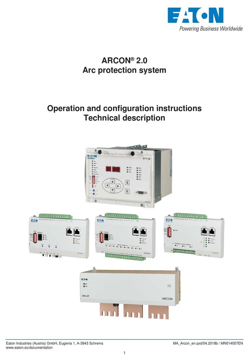
Eaton ARCON 3G User manual

Third Generation of
active arc fault protection system
For low voltage switchgear assemblies
ARCON 3G

2
ARCON 3G
ARCON 3G MANUAL MN026015EN October 2020 www.eaton.com
1 INTRODUCTION................................................3
1.1 ARCON 3G – General Outline .....................................3
1.2 Functional Scope ...............................................4
1.3 Terminal Connections............................................8
1.4 Mounting Instruction ............................................9
2 SIMPLE SYSTEM WITH ARC-LITE-3G MASTER......................14
2.1 Components .................................................15
2.2 Constellation .................................................16
2.3 Master LITE..................................................17
2.4 Detection module .............................................23
2.5 Configuration process ..........................................23
2.6 Normal operation mode ........................................24
2.7 Events & Alarms ..............................................25
2.8 Troubleshooting alarms .........................................26
3 EXTENDED SYSTEM WITH ARC-MAIN-3G MASTER .................27
3.1 Components .................................................28
3.2 Constellation .................................................30
3.3 Master MAIN ................................................31
3.4 Detection module .............................................37
3.5 Tripping module ...............................................38
3.6 Quenching device .............................................39
3.7 Display / External HMI .........................................40
3.8 Arc Protection Parameter Tool (APPT) ..............................63
3.9 Parameterization ..............................................71
3.10 Parameters ..................................................71
3.11 Events & Alarms ..............................................74
3.12 Troubleshooting alarms .........................................78
3.13 Normal operation mode.........................................80
3.14 Files ........................................................80
3.15 Operation modes (Security)......................................81
4 COMPLEX SYSTEM WITH UP TO FIVE ARC-MAIN-3G MASTER UNITS ..82
4.1 Constellation .................................................82
4.2 MASTERLINK ................................................83
5 TECHNICAL DATA .............................................84
5.1 Tests and environmental conditions ...............................84
5.2 ARC-LITE-3G .................................................86
5.3 ARC-MAIN-3G ................................................89
5.4 ARC-DMOD-3SL ..............................................93
5.5 ARC-TMOD-1QD ..............................................95
5.6 ARC-MAIN-HMI...............................................97
6 GLOSSARY...................................................98
7 LIST OF TABLES...............................................99
8 LIST OF PICTURES ...........................................101
Contents

3
ARCON 3G
ARCON 3G MANUAL MN026015EN October 2020 www.eaton.com
According to American National Fire Protection Association (NFPA), Arc Fault is a
“dangerous condition associated with the release of energy caused by an electrical arc”
as part of an Arc Fault, a type of electrical explosion or discharge that results from a
low-impedance connection through air to ground or another voltage phase in
electrical system.
Arc fault errors are the most powerful faults, which can occur in electrical installations.
Although serious precautionary measures that are given due consideration and
implemented in advance, these faults happen. They can be caused by a multitude of
factors, such as aging of the insulation, environmental conditions as well as operating
errors (human faults) or by animals entering in electrical switchboard. Electric arcs can
cause heavy damage to switchgear and present a serious hazard to operating personnel,
including heavily injures and death. In order to prevent this, the most suitable solution is
to foreseen arc fault protection systems inside electrical cabinets. These units detect the
light and increasing current of an emerging arc fault and send a trip signal to the shunt
trip of an upstream protection device such as a circuit breaker.
Figure 1.1 ARC faults errors damage curve
A conventional protection device is not able to clear the fault within a few milliseconds
and to prevent destruction of operating devices. This is where the arc protection system
establishes the connection between a short detection time and a fast response time.
ARCON 3G presents effective modular and compact system for arc protection in
low voltage switchgear assemblies, which successfully provides both, personnel and
assembly protection. ARCON 3G detects an electrical arc caused by a short circuit
through optical sensors and the load current input on the system to employ the fast
clearance of arc faults on an electrical system with a total arc mitigation time less than
2 ms.
Introduction
ARCON®3G – General outline

4
ARCON 3G
ARCON 3G MANUAL MN026015EN October 2020 www.eaton.com
Figure 1.2 Comparison of impact timing for systems with and without ARC protection
The ARCON 3G protection system is designed as modular system, so that flexible use in
different switchgears is ensured.
The ARCON 3G system provides following modules which can be used to establish
different protection levels and topologies:
ARC-LITE-3G Master LITE unit providing trip and watchdog contacts and
communication link to connected modules.
ARC-MAIN-3G Master MAIN unit providing current measurement for additional
tripping criteria, voltage measurement, trip and watchdog contact and
communication link to connected modules, HMI and Masterlink.
ARC-TMOD-1QD Tripping module to operate separate quenching device (ARC-AT).
ARC-DMOD-3SL Module for electrical arc detection via line sensor (ARC-SL).
ARC-MAIN-HMI Human Machine Interface to display and control the Master MAIN.
ARCON 3G offers three different systems (levels) of arc fault protection:
1. ARCON 3G simple arc protection system (only light criteria for arc fault monitoring)
2. ARCON 3G extended arc protection system (light & current criteria for full personnel
and assembly protection)
3. ARCON 3G complex arc protection system (up to 5 extended systems communicating
over Masterlink)
Functional scope

5
ARCON 3G
ARCON 3G MANUAL MN026015EN October 2020 www.eaton.com
ARCON 3G simple arc protection system
The ARCON 3G simple arc protection system is based on the following modules:
• ARC-LITE-3G Master LITE unit providing trip contacts & communication link to
connected Line Sensor(s).
• ARC-DMOD-3SL up to 3 Line Sensor (ARC-SL) and 1 Mobile Light Sensor (ARC-SM)
for detecting electrical arc per each module.
Master LITE unit provides 3 parallel operating fast binary tripping outputs, trip alarm and
watchdog binary outputs and 3 x 15-segment display for indication of system status /
error codes. Master LITE unit doesn’t require any programming or parameter setting. All
module housings are made of stainless and DIN rail TS35 mounting.
ote:N Up to 31 Detection modules can be interlinked to the master module via internal
CANBUS communication and maximum distance between the master module and
the last connected module is 100m.
Figure 1.3 ARCON 3G simple arc protection system

6
ARCON 3G
ARCON 3G MANUAL MN026015EN October 2020 www.eaton.com
The ARCON 3G extended arc protection system is based on the following modules:
• ARC-MAIN-3G Master MAIN unit providing current measurement for additional tripping
criteria (di/dt), voltage measurement, HMI, trip contacts & communication link to
connected modules
• ARC-DMOD-3SL Module for electrical arc detection via line sensor (ARC-SL)
• ARC-MAIN-HMI Human Machine Interface to display and control the Master MAIN
• ARC-TMOD-1QD Tripping module for external quenching device (ARC-AT)
Master MAIN unit provides 3 parallel operating fast binary tripping outputs, trip alarm
and watchdog binary outputs and 3 x 15-segment display for indication of system status
/ error codes. Master MAIN requires programming and parameter setting via separate
software (APPT) for initial setup. All module housings are made of stainless and DIN rail
TS35 mounting. (except HMI)
ARCON 3G extended arc protection system can be easily implemented in different
applications by parameter setting. ARC-MAIN-3G module has possibility to take current
rate of change (di/dt) as additional tripping criteria. Measuring values (U/I/P…etc.) are
displayed on HMI unit.
On top of that Master MAIN is able to trip external quenching device (ARC-AT) via
IGNITION PORT over Tripping module.
ote:N Up to 31 Detection modules can be interlinked to the master module via internal
CANBUS communication and maximum distance between the master module and
the last connected module is 100m.
Figure 1.4 ARCON 3G extended arc protection system
ARCON 3G extended arc protection system

7
ARCON 3G
ARCON 3G MANUAL MN026015EN October 2020 www.eaton.com
ARCON 3G complex arc protection system
Figure 1..5 ARCON 3G complex arc protection system
The ARCON 3G complex arc protection system can link up to 5 extended systems
together with MASTERLINK connection. With ARCON 3G complex arc protection system
it is possible to provide line or ring topology for the purpose of redundancy. Main purpose
of MASTERLINK is to share current criteria between master units.
Proof 1 — October 29, 2020 3:00 PM

8
ARCON 3G
ARCON 3G MANUAL MN026015EN October 2020 www.eaton.com
Terminal connections
ARC-LITE-3G – Master LITE (arc fault monitoring)
Figure 1.6 Connection diagram ARC-LITE-3G
ARC-MAIN-3G – Master MAIN (arc fault protection)
Figure 1.7 Connection diagram ARC-MAIN-3G

9
ARCON 3G
ARCON 3G MANUAL MN026015EN October 2020 www.eaton.com
ARC-DMOD-3SL – Detection module (up to 3 Line Sensors + 1 MLS)
Figure 1.8 Connection diagram ARC-DMOD-3SL
ARC-MAIN-HMI – External display and control unit (HMI)
Figure 1.9 Connection diagram ARC-MAIN-HMI
Proof 1 — October 29, 2020 3:00 PM

10
ARCON 3G
ARCON 3G MANUAL MN026015EN October 2020 www.eaton.com
ARC-TMOD-1QD – Tripping module (ignition command for quenching device)
Figure 1.10 Connection diagram ARC-TMOD-1QD

11
ARCON 3G
ARCON 3G MANUAL MN026015EN October 2020 www.eaton.com
Mounting instruction
DIN Rail modules
Figure 1.11 DIN rail installation instructions
ote:N Solid connection through uncoated and non-insulated DIN-rail profile to the
earthing concept of the enclosure. (no additional cable connection for protective
earthing required)
All ARCON 3G modules are designed for DIN rail TS35 mounting to ensure quick and
easy installation. For installation in a switchgear cabinet safety distance to adjacent
components and cabinet parts like internal shrouding, door and side panel is required.
Proof 1 — October 29, 2020 3:00 PM

12
ARCON 3G
ARCON 3G MANUAL MN026015EN October 2020 www.eaton.com
ARC-MAIN-HMI
First, it is necessary to prepare a cut-out in the door panel of the dedicated compartment.
The only restriction regarding this is the size of the existing installation surface. This may
not fall below the overall dimensions of the ARC-MAIN-HMI device.
For keeping the device position in the cut-out, employ a slight counter-pressure to the
front plate of the device and look to the backside. Each side of the housing provides two
bolt heads for installation of the fixing clamps.
While holding the ARC-MAIN-HMI device, click one fixing clamp to the bolt head which
is next to the rear of the housing.
Insertion of the device into the panel cut-out shall be conducted with a slight offset for
vertical and horizontal direction. To bring the head of the bolts into the cut-out one after
the other please push the device alternatingly into the cut-out in the following order:
right, top, left and bottom until the seal is evenly seated on the installation surface
(door panel).
Figure 1.12 Display and Control unit (HMI)
Before connecting and start-up the ARC-MAIN-HMI unit, it is necessary to install the
device into a housing or switchgear cabinet.
The following mounting instruction describes the installation of the ARC-MAIN-HMI
device as an example!

13
ARCON 3G
ARCON 3G MANUAL MN026015EN October 2020 www.eaton.com
Now, turn the fixing clamp to the second bolt head with slight pressure. Hearing a click
indicates the correct installation.
Thereafter, install the remaining three fixing clamps on the other sides of the housing.
Now the four fastened fixing clamps can be tightened by using a screwdriver.
ote:N Unmounting or changing the ARC-MAIN-HMI device can be done in reverse order.
Proof 1 — October 29, 2020 3:00 PM

14
ARCON 3G
ARCON 3G MANUAL MN026015EN October 2020 www.eaton.com
The Simple system constellation contains of one Master LITE and up to 31 Detection
modules connected via INTERLINK communication. One Detection module supports 1
MLS sensor and up to 3 Line sensors.
The Simple system supports an easy configuration process without any programming or
parameter setting.
Features:
• Stainless steel housing
• Easy mounting on DIN rail TS35
• Up to 31 light detection modules can be connected to the Master LITE via INTERLINK
communication
• Up to 100m of INTERLINK distance between the Master LITE and the last connected
light detection module
• Up to 93 Line Sensors (ARC-SL)
• Up to 31 Mobile Light Sensors (ARC-SM) for enhanced personnel protection3 x
15-segment display
• 3 parallel operating fast binary tripping outputs (NO) with ≤ 2 ms tripping time
• 1 binary trip alarm output (NO) for indication
• 1 binary Watch Dog output (NC) for system supervision
• No parameter setting required
Figure 2.1 Simple system – Block diagram
Simple system with ARC-LITE-3G Master

15
ARCON 3G
ARCON 3G MANUAL MN026015EN October 2020 www.eaton.com
Components
Description Picture
Master LITE
(ARC-LITE-3G)
Detection module
(ARC-DMOD-3SL)
Mobile Light Sensor
(ARC-SM)
Fiber Optic Line Sensor
(ARC-SL)
Table 2.1: Simple system – Components
Proof 1 — October 29, 2020 3:00 PM

16
ARCON 3G
ARCON 3G MANUAL MN026015EN October 2020 www.eaton.com
The Simple system constellation consists of one Master LITE and at least 1 up to 31
Detection modules depending on project requirements. The example of Simple system
constellation is shown on the following picture:
Figure 2.2 Simple system – Constellation
INTERLINK must be connected properly, otherwise devices can get damaged!
Constellation

17
ARCON 3G
ARCON 3G MANUAL MN026015EN October 2020 www.eaton.com
The Simple system consists of one ARC-LITE-3G and multiple number of ARC-DMOD-
3SL modules.
The Master LITE has five different areas:
1. Power connector
2. LEDs
3. Internal HMI
4. Binary Outputs
5. Communication interface
The power connector is used to power the entire Simple system topology, master itself
and all connected Detection modules via INTERLINK (RJ45 connector on the top side).
Figure 2.3 Master LITE – Power connector
Master LITE
Power connector
Proof 1 — October 29, 2020 3:00 PM

18
ARCON 3G
ARCON 3G MANUAL MN026015EN October 2020 www.eaton.com
The Master LITE has two LEDs on the front plate:
• SYSTEM
• TRIP
More details regarding the LEDs operating are available in chapter “2.7 Events & Alarms”
Figure 2.4 Master LITE – LEDs
LEDs

19
ARCON 3G
ARCON 3G MANUAL MN026015EN October 2020 www.eaton.com
Master LITE has an ordinary HMI, which could be used for configuration and
status indication.
Figure 2.5 Master LITE – Internal HMI
Internal HMI
At the end of the configuration process the user has to acknowledge the shown
information about number of detected modules and sensors as it is described in
the chapter “2.5 Configuration process”.
HMI during configuration process
HMI for status indication
At the start of normal operation mode, the display is turned off and it stays off
until system error or trip event occurs. Also, if all system errors and trips are
acknowledged the display is turned off.
There are two types of events which require acknowledgment in the normal
operation mode:
• System error
• TRIP
Proof 1 — October 29, 2020 3:00 PM

20
ARCON 3G
ARCON 3G MANUAL MN026015EN October 2020 www.eaton.com
System error
More than one system error may occur in the system. All system errors will be
written in the Event logger and each of them must be acknowledged by user in
chronological order.
Error codes are presented as E.XX1If user presses and holds INFO button
following additional information are alternately shown at intervals of 2 seconds:
• Affected module M.XX2
• Affected sensor S.XX3
When user releases INFO button the error code is shown again. User can
acknowledge the displayed system error by pressing ACK button.
TRIP
Trip is presented by event “T.13”. The TRIP event is written in the Event logger and
must be acknowledged by user. If user presses and holds INFO button following
additional information are alternately shown at intervals of 2 seconds:
Affected module M.XX4
Affected sensor S.XX5
ACK ALL alarms
To acknowledge all active alarms in the list, using only one command over internal HMI,
follow the next steps:
• Press and hold the ACK button.
• After 2s the segment display will show text: “ACK”.
• Then release the ACK button and all possible alarms will be acknowledged.
ote:N An alarm can be acknowledged only if its source is already deactivated.
1XX = EVENT NUMBER
2XX = MODULE ADDRESS
3XX = SENSOR NUMBER
Table of contents
Other Eaton Protection Device manuals

Eaton
Eaton Crouse-Hinds ZoneBarrier 4PPOE Series User manual

Eaton
Eaton CM52 User manual

Eaton
Eaton EGR-5000 User manual

Eaton
Eaton SPD160480D3M User manual

Eaton
Eaton FRCmM-NA Manual

Eaton
Eaton Powerware 9395 275 kVA MBM User manual

Eaton
Eaton Crouse-Hinds GFS Series Setup guide

Eaton
Eaton ARCON 2.0 Series Parts list manual

Eaton
Eaton SPD050208Y1K User manual

Eaton
Eaton CHSPT2MICRO Training manual