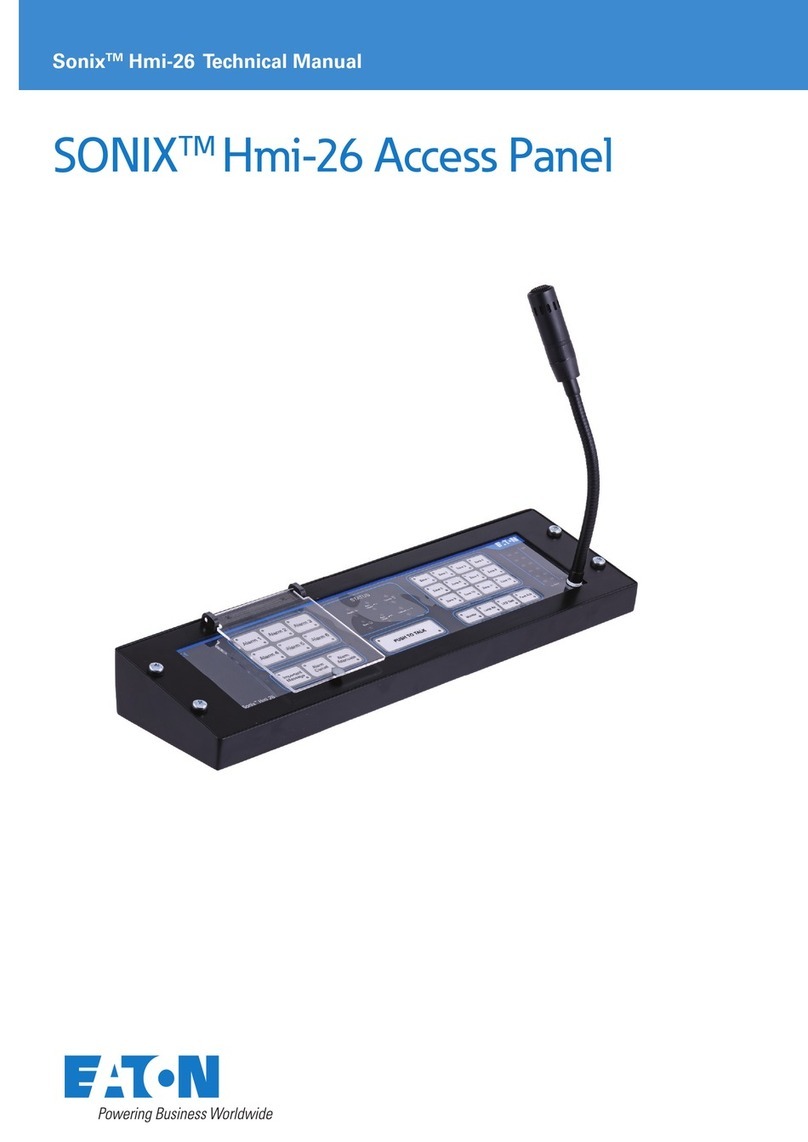
Eaton SONIX Hmi-5 User manual

SONIXTM Hmi-5
Ex Access Panel
SonixTM Hmi-5 Technical Manual

Sonix Hmi-5 Technical Manual
2
SONIX HMI-5 TECHNICAL MANUAL TM373 / A June 2022 www.eaton.com
DISCLAIMER OF WARRANTIES AND LIMITATION OF LIABILITY
The information, recommendations, descriptions and safety notations in this document are based on Eaton Corporation’s
(“Eaton”) experience and judgment and may not cover all contingencies. If further information is required, an Eaton sales
office should be consulted. Sale of the product shown in this literature is subject to the terms and conditions outlined in
appropriate Eaton selling policies or other contractual agreement between Eaton and the purchaser.
THERE ARE NO UNDERSTANDINGS, AGREEMENTS, WARRANTIES, EXPRESSED OR IMPLIED, INCLUDING
WARRANTIES OF FITNESS FOR A PARTICULAR PURPOSE OR MERCHANTABILITY, OTHER THAN THOSE SPECIFICALLY
SET OUT IN ANY EXISTING CONTRACT BETWEEN THE PARTIES. ANY SUCH CONTRACT STATES THE ENTIRE
OBLIGATION OF EATON. THE CONTENTS OF THIS DOCUMENT SHALL NOT BECOME PART OF OR MODIFY ANY
CONTRACT BETWEEN THE PARTIES.
In no event will Eaton be responsible to the purchaser or user in contract, in tort (including negligence), strict liability or
other-wise for any special, indirect, incidental or consequential damage or loss whatsoever, including but not limited to
damage or loss of use of equipment, plant or power system, cost of capital, loss of power, additional expenses in the use
of existing power facilities, or claims against the purchaser or user by its customers resulting from the use of the informa-
tion, recommendations and descriptions contained herein. The information contained in this manual is subject to change
without notice.

Sonix Hmi-5 Technical Manual
3
SONIX HMI-5 TECHNICAL MANUAL TM373 / A June 2022 www.eaton.com
Glossary
Abbreviation Meaning
PA/GA Public Address and General Alarm
Sonix Sonix PA/GA System
A&B Duplicated PA/GA system architecture
N+1 Hot spare PA/GA system architecture
AB+ Sonix improved redundancy architecture
Hmi Human interface
BGM Background music
Tick-tone Short burst of tone repeated every few seconds, used to check the output of connected loudspeakers
Sense Test Periodic test carried by Sonix amplier to check integrity of 100 V line
100 V line High voltage loudspeaker connection line at nominal 100 V ac
MCB Miniature Circuit Breaker
RCBO Residual current circuit breaker with overcurrent protection
Unit ID/Number Unique identier assigned to each of Sonix module, used to identify it to the 2Mx and SAS.
Priority Number assigned to a Sonix audio source to facilitate system usage conict resolution, 31 (highest) to 1 (lowest)
PTT Push to talk
FAT Factory Acceptance Test
SAT Site Acceptance Test
Larson’s Effect When a microphone is acoustically coupled to the loudspeaker and generates feedback
2Mx Sonix 2Mx Central controller
Amp / 350-d Sonix 350 W Power Amplier with 100 V line output
Eol1 Sonix Remote End of Line unit
Eol8 Sonix Amplier to 100 V line interface unit (8 channel)
SP AD Sonix Intelligent loudspeaker monitoring unit
Hmi-Br Sonix intrinsically safe barrier (ATEX/IECEx) for connecting Hmi-5 in explosive atmospheres
Hmi-Mute Sonix 100V loudspeaker mute (Ex/SA)
Hmi-26 Sonix Human Interface access panel
Hmi-5 Sonix Small Human Interface access panel
Io Sonix Input / Output unit
Ms12 Sonix 12-message digital message store
Pbx Sonix Private branch exchange interface unit
Pm10 Sonix Power Management unit
Vw2 Sonix Beacon control and monitoring unit (2 channel)
SAS Sonix Administration Software
Amp Bus A 2Mx bus, used to communicate with and control Sonix Amplier units
HMI Bus A 2Mx bus, used to communicate with and control Sonix Hmi units
I/O Bus A 2Mx bus, used to communicate with and control Sonix input/output devices: IG, Io and Ms12
Beacon Bus A 2Mx bus, used to communicate with and control Sonix Vw2 units
Power Bus A 2Mx bus, used to communicate with and control Sonix Pm10 units
Global Bus A 2Mx bus, used to communicate with SAS application
Sync A 2Mx bus used to communicate with the second 2Mx unit when PA/GA system is congured as A&B, AB+ or N+1
system

Sonix Hmi-5 Technical Manual
4
SONIX HMI-5 TECHNICAL MANUAL TM373 / A June 2022 www.eaton.com
1 INTRODUCTION........................................................................7
1.1 Eaton quality assurance .....................................................................7
1.2 Packaging ................................................................................7
1.3 ESD (Electro Static Discharge) ................................................................7
1.4 Safe working practice .......................................................................7
1.5 Required tools / equipment. ..................................................................7
1.6 In the box ................................................................................7
1.7 Recommended spares ......................................................................7
2 ABOUT THE PRODUCT ..................................................................8
2.1 Available features ..........................................................................8
2.2 Unit ordering and configuring.................................................................8
2.3 Conditions for use in hazardous areas ..........................................................8
2.3.1 ATEX / IECEx Certification ..............................................................8
2.3.2 ATEX / IECEx Classification ..............................................................8
2.3.3 Entity Parameters (Terminals 1 to 4 with respect to 5, I.S safety earth) . . . . . . . . . . . . . . . . . . . . . . . . . . .8
2.3.4 Special conditions for safe use ...........................................................9
3 OVERVIEW OF UNIT ....................................................................9
3.1 Weight and dimensions .....................................................................9
3.2 Power and utility...........................................................................9
4 INSTALLATION AND CONNECTIVITY .....................................................10
4.1 Mounting ...............................................................................10
4.2 Glanding ................................................................................10
4.3 Data and Audio connections ................................................................10
4.3.1 Local Mute / Local Attenuate unit ........................................................10
4.3.2 Local Power.........................................................................10
4.3.3 Un-used connectors ..................................................................11
5 UNIT OPERATION .....................................................................11
5.1 Data communications .....................................................................11
5.2 A & B duplication .........................................................................11
5.3 Microphone options .......................................................................11
5.3.1 Hand-held microphone ................................................................11
5.3.2 Flush mount microphone ..............................................................12
5.3.3 No microphone ......................................................................12
5.4 Button and LED indicator operation ...........................................................12
5.4.1 System Idle .........................................................................12
5.4.2 Indicator Test (LED Test) ...............................................................12
5.4.3 Push to Talk (with System busy indication) . . . . . . . . . . . . . . . . . . . . . . . . . . . . . . . . . . . . . . . . . . . . . . . . .12
5.4.4 Important Message (Emergency Speech)..................................................13
5.4.4.1 Combined Important Message and PTT . . . . . . . . . . . . . . . . . . . . . . . . . . . . . . . . . . . . . . . . . . . . . . . . .13
5.4.5 Zone button .........................................................................13
5.4.6 Alarm activation......................................................................13
5.4.6.1 Zoned Alarms ......................................................................13
5.4.7 Alarm Cancel ........................................................................13
5.4.8 Alarm Attenuate .....................................................................14
5.4.9 Alarm Inhibit ........................................................................14
5.4.10 Ms12 message initiation ..............................................................14
5.4.11 Local Attenuate .....................................................................14

Sonix Hmi-5 Technical Manual
5
SONIX HMI-5 TECHNICAL MANUAL TM373 / A June 2022 www.eaton.com
5.4.12 Background Music control.............................................................14
5.5 Indication only options .....................................................................14
5.5.1 System busy ........................................................................14
5.5.2 System Health / System comms health ...................................................15
5.5.3 Auto-initiated alarm ...................................................................15
5.6 Making a speech broadcast .................................................................15
5.6.1 Priority .............................................................................15
5.6.2 Zoning .............................................................................15
5.6.2.1 Zone configuration ..................................................................15
5.6.3 Microphone input ....................................................................16
5.6.4 Routine speech ......................................................................16
5.6.4.1 Routine Chime .....................................................................16
5.6.4.2 PTT Timeout .......................................................................16
5.6.5 Emergency speech ...................................................................16
5.6.5.1 Emergency speech chime ............................................................17
5.6.6 PTT Release Delay ...................................................................17
5.6.7 Mute Output ........................................................................17
5.6.7.1 Attenuate output ....................................................................17
5.7 Fault Reporting ...........................................................................17
5.7.1 Unit Monitoring ......................................................................17
5.7.1.1 Fault reporting ......................................................................17
6 CONFIGURATION .....................................................................18
6.1 Hardware configuration links ................................................................18
6.2 Solo connected access panels ...............................................................18
6.3 Fully connected access panels...............................................................18
6.4 Unit ID .................................................................................18
6.4.1 Ping-set (Set new Unit ID) .............................................................18
7 MAINTENANCE .......................................................................19
7.1 LED bulb changes .........................................................................19
8 PROGRAMMING UNITS ................................................................20

Sonix Hmi-5 Technical Manual
6
SONIX HMI-5 TECHNICAL MANUAL TM373 / A June 2022 www.eaton.com
LIST OF FIGURES
FIGURE 1 - UNIT LAYOUT..................................................................9
FIGURE 2 - HMI-5 MOUNTING HOLES ......................................................10
FIGURE 3 - A-SIDE DATA AND AUDIO CONNECTIONS . . . . . . . . . . . . . . . . . . . . . . . . . . . . . . . . . . . . . . . . . 10
FIGURE 4 - B-SIDE DATA AND AUDIO CONNECTIONS . . . . . . . . . . . . . . . . . . . . . . . . . . . . . . . . . . . . . . . . . 10
FIGURE 5 - BUTTON FLAP GUARD OPERATION ..............................................12
FIGURE 6 - PA/GA SYSTEM BROADCAST PRIORITY . . . . . . . . . . . . . . . . . . . . . . . . . . . . . . . . . . . . . . . . . . . 15
FIGURE 7 - SUGGESTED MICROPHONE POSITIONING . . . . . . . . . . . . . . . . . . . . . . . . . . . . . . . . . . . . . . . . 16
LIST OF TABLES
TABLE 1 – ATEX / IECEX CONNECTION PARAMETERS. . . . . . . . . . . . . . . . . . . . . . . . . . . . . . . . . . . . . . . . . . 8
TABLE 2 - LIST OF UN-USED CONNECTORS .................................................11
TABLE 3 - AVAILABLE ROUTINE SPEECH CHIMES.............................................16
TABLE 4 - AVAILABLE EMERGENCY SPEECH CHIMES . . . . . . . . . . . . . . . . . . . . . . . . . . . . . . . . . . . . . . . . . 17
TABLE 5 - MICROPHONE VOLUME GAIN VALUES .............................................18

Sonix Hmi-5 Technical Manual
7
SONIX HMI-5 TECHNICAL MANUAL TM373 / A June 2022 www.eaton.com
1 Introduction
These instructions are intended for all users who have
to install, commission, congure and setup the Sonix
Hmi-5 Ex access panel. For this, the manual is action-
oriented and explains how to achieve a certain objective
on a step-by-step basis. It is assumed that you have
necessary electrical, electronic and telecommunications
experience to undertake the work. If in doubt, please
consult your Eaton representative.
1.1 Eaton quality assurance
Eaton design, manufacture, install and commissions all
our products to the highest standards of quality. This
quality process is embraced and adopted throughout the
group in all areas of our operations. This is demonstrated
by our compliance and strict adherence to ISO 9001,
14001, ATEX, IECEX policies. On receipt of the
product, ensure that the cartons are undamaged and
that the contents are all correct and complete. Should
this product reach you in an unsatisfactory condition
please report this to Eaton to enable us to rectify and
investigate the fault in a speedy manner.
1.2 Packaging
In the interest of preserving the environment, Eaton aims
to use recycled packaging wherever practical. Due to the
physical nature of our products, we provide adequate
packaging to protect the goods during transit. Please
ensure that once unpacked, checked and installed that
all packaging is disposed / recycled in a responsible
manner.
1.3 ESD (Electro Static Discharge)
The Sonix PA/GA system is largely constructed from
electronic printed circuit boards. These printed circuit
boards are sensitive to static electricity, ESD discharge
on to any of the Eaton products could cause permanent
and irreparable damage to the equipment. All such
PCB’s are shipped to you in ESD protective bags for
transit. Prior to opening the transit bags please ensure
that you are wearing either an ESD, earthed wrist strap
or other suitable means of protection.
1.4 Safe working practice
Whilst working on or within the Sonix PA/GA system it
is our prime interest that you remain safe throughout.
During this work you will be exposed to potentially
hazardous voltages, currents, confined spaces and
potentially industrial environments.
Prior to undertaking any work please ensure relevant
permits and regulations are adhered to.
1.5 Required tools / equipment.
To install and commission this part you will need the
following tools.
• Flat-blade terminal screw driver
• Large PH1 screw driver
• Multi-meter
• 4 off mounting screws, M6 or equivalent
1.6 In the box
This item is shipped with the following items.
• 1 x Hmi-5 access panel
• 1 x Product Manual
1.7 Recommended spares
This item is sold as a complete module therefore, no
spares are necessary.

Sonix Hmi-5 Technical Manual
8
SONIX HMI-5 TECHNICAL MANUAL TM373 / A June 2022 www.eaton.com
2 About the product
The Sonix Hmi-5 Ex is an intrinsically-safe Human
Interface access panel for connection into the Sonix
PA/GA system from harsh and hazardous locations. It
can provide operators with the ability to interface with
the system to activate and control alarms and make
announcements, both routine and emergency speech.
The units are remotely congurable using the Sonix
administration software with several features that can
be tailored to the needs of system installation.
The unit is an A & B duplicated unit with independent
and isolated circuits for A side and B side. Each side is
typically phantom powered from the PA/GA system rack
and has been designed to be a low power solution. The
unit is in an IP66 rated enclosure.
2.1 Available features
• Atex / IECx EExi certified when installed with Sonix
Hmi-Barrier
• Up to 5 Manual activation buttons with built-in low
power LED status indication
• Hand-Held or Flush mount microphone options
• Alarm activation and control options including:
• Alarms 1-6
• Alarm Cancel
• Alarm Attenuate
• Routine speech
• With pre-set zoning
• Emergency speech
• All-Call or with pre-set zone control
• Zone buttons
• LED Lamp test
• Unit self-monitoring and fault reporting
• Remote configuration using Sonix software
2.2 Unit ordering and conguring
Due to the multitude of button permutations for the
limited number of buttons and indicators available on the
Hmi-5, each unit is customised for the required system
functionality. The specic functionality needs to be
discussed and specied before and during ordering with
your local Eaton representative.
2.3 Conditions for use in hazardous areas
2.3.1 ATEX / IECEx Certication
ATEX Certificate ITS 13 ATEX 27897 X
Certified to EN 60079-0, EN 60079-11, EN
60079-26
IECEx Certificate IECEx ITS 13.0048X
Certified to IEC 60079-0, IEC 60079-11,
IEC 60079-26
2.3.2 ATEX / IECEx Classication
ATEX
II 1 G Ex ia IIC T4 Ga
Tamb: -40C up to +60C
IECEx
Ex ia IIC T4 Ga
-40°C ≤ TA ≤ +60°C
2.3.3 Entity Parameters (Terminals 1 to 4 with respect to
5, I.S safety earth)
Between connection points:
Entity
Parameter 1 to 5 2 to 5 3 to 5 4 to 5
Ui 26.1 V 26.1 V 7.9 V 7.9 V
Ii 138 mA 138 mA 37 mA 37 mA
Pi 897 mW 897 mW 72 mW 72 mW
Ci 0 F 0 F 0 F 0 F
Li 0 H 0 H 0 H 0 H
Table 1 – ATEX / IECEx Connection parameters

Sonix Hmi-5 Technical Manual
9
SONIX HMI-5 TECHNICAL MANUAL TM373 / A June 2022 www.eaton.com
2.3.4 Special conditions for safe use
• The metallic screw fastener used to anchor the
cable to the enclosure of the handheld microphone
is electrically isolated from all surrounding materials
and has a capacitance of 10.8pF. The installer/user
must ensure the suitability of the equipment for the
application and take precautions to ensure that this
part does not accumulate an electrostatic charge.
• All cable glands, blanking elements and threads
adapters must be certified Ex e or Ex d components
designed for use in Gas Group IIC and giving a
minimum degree of protection IP64.
• Entity parameters of the equipment are guaranteed
by the associated safety interface board “HMI Br”
certified under certificate ITS13ATEX27896X. In order
to ensure the integrity of safety components inside
or outside the hazardous area, the Hmi 5 shall not be
used without the “Hmi Br”. Use of the Hmi 5 without
connection of the Hmi Br invalidates the type of
protection stated within this certificate.
• Installation shall be in accordance with the
manufacturer’s instructions. Use of terminal J2, J4,
J16, J6 J8 or J17 even whilst in a non-hazardous area
invalidates the type of protection stated within this
certificate.
• The installer and user of this equipment must make
provision for the avoidance of accumulation of
electrostatic charge on the surface of the equipment.
3 Overview of unit
Figure 1 - Unit layout
Item Description
1IP66 Enclosure
2Configurable Buttons (up to 5) with integrated flap guard
3Flush Microphone (Option)
4Hand-Held Microphone (option)
5Hand-Held Microphone hanger
6Certification label
3.1 Weight and dimensions
Un-packed: up to 2.0 Kg, 160 x 90 x 260 mm
3.2 Power and utility
Voltage: 24 V dc phantom powered from partner
equipment in the PA/GA system
Current: 50 mA max consumption
Hmi-5 Certification
Label
Hmi-5 Certification
Label
5
1
J1
A
5
1
J16
5
1
J5
B
5
1
J17

Sonix Hmi-5 Technical Manual
10
SONIX HMI-5 TECHNICAL MANUAL TM373 / A June 2022 www.eaton.com
4 Installation and connectivity
4.1 Mounting
The unit should be installed securely using appropriate
fixings, not supplied.
Figure 2 - Hmi-5 Mounting holes
ote:N The Hand-held microphone hanger can be damaged by rough
handling, take care when mounting the unit.
4.2 Glanding
The Sonix Hmi-5 is typically supplied with 2 or more
M20 tapped holes for cable gland terminations.
Warning: Cable glands must be installed and
inspected correctly to maintain Ex and IP ratings.
4.3 Data and Audio connections
Data and audio connections to the unit should be wired
with 2 pair and screen cable, with both individual and
overall screen for improved noise performance. The unit
uses 1 pair for outgoing audio with incoming phantom
power superimposed on the top. The second pair is
used for bi-directional serial communications at 9,600
8-N-1 baud for control and status reporting. The screen
connection is required as part of the 0V return. The
maximum cable distance that the system can support
for an Hmi-5 is 300 m, connections longer than this
are not supported and are likely to result in un-reliable
operation.
Connections to a Sonix Hmi-Barrier should be wired pin-
to-pin without any crossover.
A side PA/GA Assignment Hmi-5
Connection
2off Twisted pair, individual and overall
screen.
1.5 mm² to 2.5 mm² (max ferruled)
SWA / SWB
Audio + J1 – 1
Audio - J1 – 2
Data In J1 – 3
Data Out J1 – 4
Screen J1 – 5
Figure 3 - A-Side Data and Audio connections
B side PA/GA Assignment Connection
2off Twisted pair, individual and overall
screen.
1.5 mm² to 2.5 mm² (max ferruled)
SWA / SWB
Audio + J5 – 1
Audio - J5 – 2
Data In J5 – 3
Data Out J5 – 4
Screen J5 – 5
Figure 4 - B-side Data and Audio connections
4.3.1 Local Mute / Local Attenuate unit
Connections to activate a local mute and/or local
attenuate unit are made into the corresponding A or B
PA/GA rack, driven from the associated Hmi-Tu (see
Hmi-Tu and Mute manuals).
Warning: Do NOT connect a Mute control line to
an Hmi-5 unit.
4.3.2 Local Power
The Sonix Hmi-5 unit is not intended to be powered
locally and should only be powered via the phantom
feed.
Hmi-5 Certification
Label
240.0mm
110.0mm
Ø6.0mm
2
1
2
8 – 12 cm
Hmi-5 Certification
Label
Hmi-5 Certification
Label
5
1
J1
A
5
1
J16
5
1
J5
B
5
1
J17
Hmi-5 Certification
Label
Hmi-5 Certification
Label
5
1
J1
A
5
1
J16
5
1
J5
B
5
1
J17

Sonix Hmi-5 Technical Manual
11
SONIX HMI-5 TECHNICAL MANUAL TM373 / A June 2022 www.eaton.com
4.3.3 Un-used connectors
The unit has connectors which are not certified for
intrinsically safe installations and must not be used
in the hazardous area. It is recommended the unit be
removed from the hazardous area if reprogramming the
functionality of the unit is required. The connectors are
listed below:
Connector Function For use by Eaton
Personnel only
J2, J6 Local power Yes
J16, J17 Audio and data expansion Yes
J4, J8 Programming Yes
Table 2 - List of un-used connectors
5 Unit operation
5.1 Data communications
The Hmi-5 unit communicates with the Sonix PA/GA
system rack via an Hmi Tu using a low power serial
and a balanced audio pathway. The protocol used is
a proprietary Sonix datagram format with messages
exchanged every 100ms. The datagrams contain system
status and activity from the PA/GA and access panel
status and activity going to the PA/GA rack. While
idle the Hmi-5 access panel is transmitting low level
audio that is monitored by the PA/GA rack to detect
degradation in the audio pathway.
The Hmi-5 implements different electrical interface
to the Sonix Hmi-26 access panel and this requires a
hardware link change on the Hmi Tu (see Hmi Tu manual
for details).
5.2 A & B duplication
The Sonix Hmi-5 access panel is a duplicated unit with
an A and B side. There is a small common section,
namely Microphone, Buttons and indicators. The two
sides signal each other basic status, this facilitates
passing control of the LED indicators to the side in
the best state. By default A side will control the LED
indicators.
Warning: Both sides of an Hmi-5 need to have
identical functionality and conguration to ensure
correct operation.
ote:N It is not required to use both sides, if non-duplicated operation is
required A side should be used in preference.
5.3 Microphone options
The standard Hmi-5 unit is designed and customised
for each order, which is then tailored to the user’s
requirements. Please discuss specific requirements with
your local Eaton representative before ordering.
5.3.1 Hand-held microphone
The standard microphone is a hand-held variant on
a coiled cord, complete with hanger to place the
microphone when not in use. The microphone has an
integral PTT button on the side.
In this configuration it is possible to have up to 5 push
buttons with built-in LED indicators on the unit itself.

Sonix Hmi-5 Technical Manual
12
SONIX HMI-5 TECHNICAL MANUAL TM373 / A June 2022 www.eaton.com
5.3.2 Flush mount microphone
The flush mount variant takes up the space of a normal
button, reducing the maximum button count to 4,
additionally the one of the buttons will have to be
reserved to function as a PTT input.
5.3.3 No microphone
It is also possible to order the Hmi-5 without any
microphone at all, this configuration again has a
maximum of 5 buttons with built-in LED indicators
available.
5.4 Button and LED indicator operation
Each button on the Sonix Hmi-5 can be utilised to
perform a pre-set function. The available functions are
discussed later in this section.
Each button can also be disabled in configuration,
which prevents the button press but does not affect the
indicator operation. This can allow for future expansion
and protected functionality in insecure/remote locations.
Activity indication styles available on buttons:
Off Typically used to indicate associated function is
not active
Slow flashing (~ 0.5 Hz)
Typically used to indicate associated function is
active on the system but not from local access
panel-
Fast flashing (~ 5 Hz) Typically used to indicate associated function is
pre-selected on the access panel
Solid Typically used to indicate associated function is
active on local access panel and system
Breathing (see 6.4.1) Typically used to indicate the access panel is idle
ote:N The breathing indication will stop across all indicators on any but-
ton or indicator activity.
Each indicator can be one of the following colours:
• Red
• Blue
• Yellow
• Green
• Clear
• Orange
• Black (Non-illuminating)
ote:N The standard Hmi-5 push buttons are fitted with long life LED
indicators that have a long MTBF and should not require replacement.
Warning: The IP rating of the Hmi-5 unit
depends on correct construction of the button
and LED indicator, opening the button to change
the LED can adversely affect the rating. Please
contact your local Eaton representative for
guidance on this matter.
The buttons have optional, fitted by default, clear flaps
to prevent accidental operation. These must be specified
during ordering due to the need to maintain IP66 rating
and prevents post-delivery installation.
The flap has a simple operation and will stay open
unless closed.
Figure 5 - Button ap guard operation
Warning: The standard Hmi-5 pushbuttons
normally closed, open when activated, this
means that a broken or loose connection can
cause un-intended activations.
5.4.1 System Idle
During system idle the LED indicators are normally
set up to slowly ‘breathe’. This involves a constantly
varying brightness on the LED at a fairly dim level to give
confidence that the unit is powered, and the indicators
are functional. This has been carefully designed to make
it easy to distinguish between idle and active / off.
5.4.2 Indicator Test (LED Test)
Indicator lamp test button is intended to provide a
simple mechanism for routine maintenance testing of all
indicators on the unit.
On activation all indicators will illuminate solid for at least
1 second and then extinguish and return to indicating the
current state; typically idle.
5.4.3 Push to Talk (with System busy indication)
Push to talk can be assigned to be either a standard
button or the button incorporated on the hand-held
microphone.
If assigned to a standard button the associated indictor
has the following states:
Off PTT is not active
Slow flashing (0.5 Hz) System is busy
Solid PTT is active
ote:N The Hand-held microphone push to talk button is recommended
as it allows for increased functionality on the unit.
ote:N The default PTT action is for Routine Speech broadcast. To broad-
cast emergency speech an Important message button needs to be
available or the required functionality to be defined during ordering.
Warning: The default zoning of PTT must be
specied as part of unit ordering.
Hmi-5 Certification
Label
240.0mm
110.0mm
Ø6.0mm
2
1
2
8 – 12 cm

Sonix Hmi-5 Technical Manual
13
SONIX HMI-5 TECHNICAL MANUAL TM373 / A June 2022 www.eaton.com
5.4.4 Important Message (Emergency Speech)
Important Message is a toggle action button. It will
normally self-clear after ~30 seconds of no action of
either a button press or PTT broadcast. The standard set
up is to require a second action to broadcast Emergency
Speech, i.e. to actively select Important Message then
begin broadcast with PTT.
If assigned to a standard button the associated indictor
has the following states:
Off Important Message is not active
Slow flashing (0.5 Hz) An Important Message is being broadcast on the
system
Solid Important Message is active on the local panel
(may or not be broadcasting)
ote:N An important message broadcast is to all areas unless specified
as part of the unit ordering.
5.4.4.1 Combined Important Message and PTT
A combined PTT and Important Message button will
broadcast Emergency Speech while activated.
The indicator will follow the same pattern as for standard
PT T.
Warning: Check regulatory requirements
regarding Emergency Speech broadcasts as
some require a two-step process to avoid
accidental activation.
5.4.5 Zone button
Zone buttons can be used to give the Hmi-5 access
panel increased speech broadcast exibility by allowing
the pre-selection of broadcast zones before activation of
PT T.
Zone buttons have a timeout of ~6 seconds. If no PTT
or additional zone button activation occurs within this
time window, they all self-clear. Each button activation
resets the timeout counter.
Warning: The default zoning of PTT and zone
buttons must be specied as part of unit
ordering.
If assigned to a standard button the associated indictor
has the following states:
Off Associated Zone(s) are not active
Slow flashing (0.5 Hz) Associated Zone(s) are being broadcast into by
the system
Fast flashing (5 Hz) Associated Zone(s) are pre-selected by the local
panel (PTT not active)
Solid Associated Zone(s) are selected by the local panel
(may or not be broadcasting)
5.4.6 Alarm activation
Alarm activation buttons can be set to activate any one
of Alarms 1 to 6. Alarms by default are all areas, but
xed function zoned alarms are possible (see 6.4.6.1
Zoned alarms).
Typical associated indicator function:
Off Associated Alarm is not active
Slow flashing (0.5 Hz) Associated Alarm is active on the system but not
from the local access panel
Solid Associated Alarm is active from the local access
panel
ote:N Alarm activation function within Sonix PA/GA is NOT a toggle
action, clearing the alarm requires activation of Alarm Cancel.
5.4.6.1 Zoned Alarms
Alarm activation function on the Sonix Hmi-5 are
usually All-Call, i.e. activates the alarm into all areas. It
is possible to change the default action to be a zoned
alarm
ote:N This is not recommended but if zoned alarm activation is required
please discuss with local Eaton representative.
5.4.7 Alarm Cancel
Alarm Cancel button is provided to allow a user to clear
or ‘cancel’ active alarms on the system. Please note
that once pressed there is no method of un-actioning an
Alarm Cancel.
Activating Alarm Cancel button will send a signal to
the 2Mx requesting a clear out of any currently active
alarms. If the activation input is still active, for example a
remote push-button connected into the IO-Tu, then the
alarm will immediately re-activate (although the audio
will pause for up to a second). The alarm cancel signal
self clears after ~ 200 milliseconds to prevent a broken
or stuck button from acting as an un-intended alarm
inhibit.
If assigned to a standard button the associated indictor
has the following states:
Off Alarm Cancel is not active
Fast flashing (5 Hz) Alarm Cancel is active on the system
Solid Alarm Cancel is active locally but not on the
system
ote:N : As part of system design for un-attended access panels in pub-
lic spaces; consideration should be taken as to whether Alarm Cancel is
a protected function.

Sonix Hmi-5 Technical Manual
14
SONIX HMI-5 TECHNICAL MANUAL TM373 / A June 2022 www.eaton.com
5.4.8 Alarm Attenuate
Alarm attenuate is a toggle action function, it will only
latch on if an Alarm is active on the PA/GA system.
The alarm attenuate action operates at a system level,
activating this button toggles the current system state
independent of the access panel.
If assigned to a standard button the associated indictor
has the following states:
Off Alarm Attenuate is not active
Fast flashing (5 Hz) Alarm Attenuate is changing state
Solid Alarm Attenuate is active
5.4.9 Alarm Inhibit
Alarm Inhibit is used to prevent automated activation
of alarms from external systems such as Fire & Gas.
It does not prevent manual activation from any access
panel.
If assigned to a standard button the associated indictor
has the following states:
Off Alarm Inhibit is not active
Fast flashing (5 Hz) Alarm Inhibit is active on the system
Solid Alarm Inhibit is active locally
ote:N Not a recommended action for an Hmi-5 access panel. Eaton
recommends that a key switch connected to Sonix Io would be a more
rigorous solution.
5.4.10 Ms12 message initiation
Initiation of a pre-recorded message from the Ms12. The
message can only be initiated if it is loaded (recorded)
and enabled on the Ms12.
If assigned to a standard button the associated indictor
has the following states:
Off Button is not active
Fast flashing (5 Hz) Button is active, message playback requested
ote:N There is no success/failure feedback to the user on the access
panel.
5.4.11 Local Attenuate
Local attenuate is a toggle action function, it can be
used at any point to reduce the output of the local
loudspeaker(s).
Typically, Local Attenuate will be implemented with a
pre-set timeout window to prevent permanent latch up,
values between 5 and 30 minutes.
If assigned to a standard button the associated indictor
has the following states:
Off Local Attenuate is not active
Fast flashing (5 Hz) Local Attenuate is changing state soon
Solid Local Attenuate is active
5.4.12 Background Music control
Background music is an optional feature of the Sonix PA/
GA system, its management and control are not covered
in this manual. Please the 2Mx and SAS manuals for
more information.
BGM control is a change state request action function
that allows remote control of BGM. It requires a number
of Sonix components to be correctly congured to work.
If assigned to a standard button the associated indictor
has the following states:
Off Button is not active
Solid Button is active, BGM state change requested
ote:N There is no success/failure feedback to the user on the access
panel.
ote:N Replaces Local Attenuate, cannot be used together.
5.5 Indication only options
Any of the features above with indicator states can be
used as an indicator only with the push button disabled
in conguration.
The following are options for using a button as indication
only without any on-press event associated.
5.5.1 System busy
System busy indicator is used to show when the system
has active.
If assigned to a standard button the associated indictor
has the following states:
Off System is currently idle
Fast flashing (5 Hz) Engineers panel active on the system
Solid System is busy with an Alarm, Routine or
Emergency speech

Sonix Hmi-5 Technical Manual
15
SONIX HMI-5 TECHNICAL MANUAL TM373 / A June 2022 www.eaton.com
5.5.2 System Health / System comms health
System health indicator is used to show the system
health and local access panel communications health
status. Due to the single indicator colour, the indicator
can be used to show either a system healthy or a
system fault.
If assigned as a system fault light the indictor has the
following states:
Off System is currently healthy, or access panel is
powered
Fast flashing (5 Hz) Local communications issue
Solid System is not healthy
ote:N Eaton recommends this mode, especially when combined with
idle indicator breathing (see 6.4.1) and suggests a Red button cover/
indicator colour.
If assigned as a system healthy light the indictor has the
following states:
Off System is NOT healthy, or access panel is
powered
Fast flashing (5 Hz) Local communications issue
Solid System is currently healthy
ote:N Green button cover/indicator colour would be suitable for this
mode.
5.5.3 Auto-initiated alarm
Auto initiated alarms are alarms that originate from third-
party interfaces into the Sonix Io unit. Example might
include Fire & Gas systems.
Off System has NO active auto-initiated alarm
Solid System has an active auto-initiated alarm
5.6 Making a speech broadcast
Speech broadcasts on Sonix systems are made of up
three parts:
• the audio from the user (see section 6.6.3),
• a priority set by the access panel/source (see section
6.6.1),
• a zone map to define where the broadcast needs to
go (see section 6.6.2).
5.6.1 Priority
The priority within the Sonix PA/GA system is two-part
system:
1. Firstly, the activity type has a basic priority order:
a. Emergency Speech (Higher)
b. Alarms
c. Routine Speech (Lower)
2.Secondly, the audio source unit has priority number
ranging from 1 to 31, where 1 is the lowest and 31 is
the highest priority.
Warning: Priority is congured on a unit basis
and must be unique across the system to the
controller it is connected to. The Hmi-5 should
have both A & B sides, if both are in use, set to
the same priority.
Emergency Speech
31 Highest
…
1
Alarms
Alarm 1
…
Alarm 12
Routine Speech
31
…
1Lowest
Figure 6 - PA/GA System broadcast priority
5.6.2 Zoning
Before activating PTT to make an announcement, the
user can either use the default congured zones or
select the required zoning for the broadcast.
5.6.2.1 Zone conguration
Zone button and zone conguration is calculated as part
of system design, please discuss your requirements
with your local Eaton representative.
Warning: Zone mapping is built into the
rmware and is currently not congurable in
the eld.

Sonix Hmi-5 Technical Manual
16
SONIX HMI-5 TECHNICAL MANUAL TM373 / A June 2022 www.eaton.com
The available zone maps are:
Default Routine Speech Set on a project level, typically into Process/
External areas
Default Emergency
Speech Typically set to All-Call
Zone map Button(s) Configured to cover a sub-set of available zones
(Multiple buttons are allowed)
Alarm activations Set to All-Call
5.6.3 Microphone input
The microphone input on the Hmi-5 can be either a ush
mounted microphone on the chassis or a Hand-Held
microphone on a exible coiled lead.
The ush mount microphone is intended to be used
from between 8 and 12 cm from the user whereas the
Hand-Held microphone is intended to be held close to
the talker, in the 4-8 cm range.
Figure 7 - Suggested microphone positioning
The microphone sensitivity can be adjusted on request,
please contact your local Eaton representative.
5.6.4 Routine speech
A Routine speech broadcast is activated by pressing the
Push to Talk (PTT) button, either on the unit or in the
case of a Hand-Held microphone the PTT button is on
the microphone itself.
5.6.4.1 Routine Chime
The Hmi-5 can be congured to play one of three
different chimes before each routine speech broadcast,
the chimes are referred to as single, double and triple
bong. Selection of a chime creates a delay between
activating PTT and routing voice to the PA/GA system
while the chime plays.
Chime Name Sound Notes
Single Bong 660Hz decaying gong
over ~4seconds
The decaying gongs have the
new gong superimposed over
the top after ~1.1s
Double Bong
660Hz then 550Hz
decaying gongs over
~5.5seconds
Triple Bong
660Hz then 550Hz then
400Hz decaying gongs
over ~7seconds
None No chime
No chime is generated, and
voice is routed to the system
without delay
Table 3 - Available Routine Speech Chimes
Chime can be disabled for routine speech broadcasts.
5.6.4.2 PTT Timeout
The audio system on the Hmi-5 can be congured to
have a maximum transmit time, called PTT Timeout.
When this setting is active the access panel will cancel
the active PTT session if it exceeds the time set in the
conguration. Valid values range from 30 seconds to 120
seconds with no timeout also an option.
If this timeout event occurs, the Hmi-5 access panel
will also generate a PTT Timeout fault. This can be
used to identify situations where the PTT button has
been accidentally depressed or no longer functioning
correctly.
The PTT timeout fault can be disabled in conguration.
5.6.5 Emergency speech
Emergency speech, sometimes referred to as Important
Message, is a method for increasing the priority
of a speech broadcast, combined with a different
announcement tone. Within the Sonix PA/GA system
emergency speech is the only way to broadcast
speech over an active alarm. Flagging a broadcast as an
Important message increases its priority.
Emergency speech is selected by pressing the
Important Message button, this button is a toggle
button with timeout. The timeout is ~30 seconds since
the feature was activated or since the last Emergency
speech broadcast from the access panel nished.
Hmi-5 Certification
Label
240.0mm
110.0mm
Ø6.0mm
2
1
2
8 – 12 cm

Sonix Hmi-5 Technical Manual
17
SONIX HMI-5 TECHNICAL MANUAL TM373 / A June 2022 www.eaton.com
5.6.5.1 Emergency speech chime
The Hmi-5 can be congured to play one of three
different chimes before each emergency speech
broadcast, the chimes are different to the routine
speech chimes. Selection of a chime creates a delay
between activating PTT and routing voice to the PA/GA
system while the chime plays.
Available chimes on the Hmi-5 are:
Chime Name Sound Notes
Chime 1 1 kHz tone for 1second Long beep
Chime 2 1 kHz tone 400ms ON
400ms OFF 400ms ON Double beep
Chime 3
1 kHz tone 100ms ON
100ms OFF repeated 5
times
Multiple fast beeps
None No chime
No chime is generated and
voice is routed to the system
without delay
Table 4 - Available Emergency Speech Chimes
Chime can be disabled for emergency speech
broadcasts.
5.6.6 PTT Release Delay
The Hmi-5 has a conguration option called PTT Release
Delay, commonly called a ‘Slug Time’. This setting
makes the access panel internally keep the PTT button
active for between 1 and 3 seconds after release. This
will allow a user to correct for a digit slipping off the
button unintentionally.
ote:N Installations using both A & B side of the Hmi-5 should ensure
both sides have identical audio configuration to prevent audio artefacts
breaking onto the PA/GA system.
This feature can also be disabled by setting the PTT
Release Delay to None.
5.6.7 Mute Output
The Hmi-5 access panel has no direct outputs for
controlling speaker Mutes and speaker Attenuates,
these outputs are instead generated by the Sonix PA/GA
system rack via the Hmi Tu.
The Mute output activates when the Hmi-5 is the active
PTT broadcast on the PA/GA system. This approach
allows the user to hear any overriding broadcasts if they
are not the one active on the system.
5.6.7.1 Attenuate output
Additionally, the Hmi-5 can control a second output
intended to activate a local speaker attenuate. The
attenuate feature is provided to allow operators to
reduce the volume of an alarm in the local area. The
attenuate output, identical to the Mute output, activates
on active PTT broadcast but can additionally be
controlled manually by the user.
ote:N The Local Attenuate button has an alternative function when dis-
abled and is used to control BGM playback, but the outputs will activate
for short periods of time in this mode. See section 6.4.12 on BGM.
5.7 Fault Reporting
5.7.1 Unit Monitoring
The Hmi-5 access panel has built in status monitoring
to detect any issues early. The following features are
monitored:
• Microphone input is monitored for open (high
impedance) and short (low impedance)
• Internal Audio pathways – These are monitored using
DTMF signalling while unit is idle
• Incoming Data communications from PA/GA system
are monitored for presence and quality
• PTT is monitored for stuck switch – See section
5.6.4.2
• Inter-FPGA health – The independent halves of the
Hmi-5 communicate with each other, loss of this
communication is considered a fault
Some of these monitoring circuits can be disabled in
conguration, see section 7.
5.7.1.1 Fault reporting
The Sonix PA/GA system has a robust fault reporting
system; all issues with individual units are reported
to the 2Mx central controller using the datagram
messages. Communication links and missing units are
also monitored by the 2Mx central controller. The 2Mx
central controller then forwards the datagrams on to the
software and sends a generic fault ag back to all the
connected units.

Sonix Hmi-5 Technical Manual
18
SONIX HMI-5 TECHNICAL MANUAL TM373 / A June 2022 www.eaton.com
6 Conguration
The Hmi-5, like most of Sonix, has been designed to be
congurable via the common Sonix software interface.
For most of the conguration options for the Hmi-5
access panel, please see the Sonix Administration
Software (SAS) user manual.
6.1 Hardware conguration links
There are no hardware conguration (jumper) links on
the Sonix Hmi-5 unit.
6.2 Solo connected access panels
Hmi-5 access panel installed with a single data
connection should be installed and congured with the
following options:
• Use the A-side terminals, even if intended to be
connected as part of a B-system installation. There
are common circuits that can only be adjusted by the
A side.
• Disable Inter-FPGA fault monitoring.
6.3 Fully connected access panels
An Hmi-5 with data connections to both A and B sides
should have the followings settings/considerations:
• Priority must be identical
• Unit ID should be identical but not essential
• Enable Inter-FPGA fault monitoring.
• Ensure the audio options are identical:
• Routine Chime
• mportant Message Chime
• PTT Release delay
• PTT Timeout
• Microphone volume
• The other setup options should be the same:
• Fault monitoring
• Firmware controlled functionality should be identical:
• Available buttons
• Zoning
• Alarms
6.4 Unit ID
Each Hmi-5 access panel on a system needs to have
a unique identier, called a Unit ID or number. This
number, between 1 and 31, is used to identify the
access panel to the 2Mx central controller and SAS
software.
To read or change conguration or set the Unit ID, SAS
installed on computer and Sonix data connection cable
are required. Please see the SAS user manual for more
details.
6.4.1 Ping-set (Set new Unit ID)
ote:N It is likely that multiple persons will be required due to limited
time window to accept the new ID.
To ping-set an Hmi-5 the following procedure needs to
be followed:
1. Connect Computer with SAS installed and working to
the system via the data connection cable
2.Navigate to Hmi-5 configuration screen
3.Press Ping-set and enter a new Unit ID
Note: Unit ID’s need to be unique for Hmi-5’s on the
system, but same for A/B sides
4.Once the software has sent the ping-set command
ALL Hmi-5 access panels that receive the command
will illuminate all LEDs for ~10 seconds
ote:N If A side is powered up and Ping-set is sent to B-side only the
LEDs will NOT illuminate.
5.Pressing both left hand buttons* together on the
Hmi-5 access panel during this 10 second window
will cause that local panel to accept the new Unit ID
This is where a second person standing by the panel is
required
6.Any Hmi-5 access panel which has not had the
accept procedure pressed during the 10 second
window will discard the command and retain their
current Unit ID and configuration
ote:N The exact button presses required depend on the hardware and
firmware on the unit, but standard configuration is both left hand but-
tons together.
ote:N
6.5 Priority
Priority is set on a unit by unit basis as part of the
general system configuration. See SAS manual and
section 6.6.1 for more details
6.6 Microphone Volume
The Hmi-5 access panel has the ability to reduce the
sensitivity of the microphone.
Values range as follows:
Setting Value Gain
Full volume 15 0
Mid volume 7-2.5 dB
Low volume 0-5.5 dB
Table 5 - Microphone volume gain values
ote:N The unit must be fully power cycled after changing the volume
setting to allow the gain to be adjusted.

Sonix Hmi-5 Technical Manual
19
SONIX HMI-5 TECHNICAL MANUAL TM373 / A June 2022 www.eaton.com
7 Maintenance
The Hmi-5 unit itself does not require any specic
maintenance but the following general maintenance
should be performed monthly.
Warning: Make sure to follow any local
regulations on hazardous area before opening
units.
• Check the unit for visible damage (scratches, bumps)
• Check connections and cable integrity - replace
damaged cables, tighten terminal connectors loose
screws
• Check unit fixing to rack / console – tighten loose
screws
• Check microphone for loosening of the Goose-Neck
• Remove dust and dirt from front panel - Clean with a
dry cloth
Warning: Remove fuse / power off the unit
before proceeding.
ote:N Do not use sharp objects, water, aggressive cleaning agent or
solvent to clean the unit.
7.1 LED bulb changes
Warning: The IP rating of the Hmi-5 unit
depends on correct construction of the button
and LED indicator, opening the button to change
the LED can adversely affect the rating. Please
contact your local Eaton representative for
guidance on this matter.
The LED indicators tted to the Sonix Hmi-5 are long
life units designed not to be replaced within the typical
lifespan of the unit. If it becomes necessary to change
the indicator during service lifetime care must be taken
to properly re-assemble the button unit to ensure IP
ratings.
Warning: Inserting the new LED indicator will
most likely result in a button activation, ensure
local procedures have been followed before
commencing work.
Replacement LED: EAO 10-2109.1069 12V white
1. Lift flap guard
2.Using medium tack adhesive tape, rotate the coloured
lens anti-clockwise
3.Carefully remove lens
4.Remove white diffuser plate
5.Extract LED unit, noting orientation of +ve leg
6.Insert replacement LED unit, matching orientation of
removed unit
Note: This will require a firm press on the LED and
result in a button activation if enabled/powered
7. Test LED operation before continuing
8.Carefully re-insert white diffuser plate, chamfered
edge inwards, engaging the protrusions in the outer
edge with the corresponding pockets
9.Replace lens cover, taking care to avoid cross-
threading
10.Tighten lens cover
Warning: The diffuser MUST be tted and
carefully aligned and lens cover fully tightened to
maintain IP66

Sonix Hmi-5 Technical Manual
20
SONIX HMI-5 TECHNICAL MANUAL TM373 / A June 2022 www.eaton.com
8 Programming units
The Hmi-5 access panels are controlled by a Microsemi
ProASIC3 FPGA with instant-on technology for fast and
reliable operation.
Required equipment for programming units:
• Computer/laptop with Microsemi FlashPro 11.x
installed
• Microsemi Flash Pro 4 or newer programmer
• Connection cable for programmer to unit (2x5 0.1”
pitch)
• Eaton firmware for target unit – Verify firmware is for
correct unit
• Power source for Hmi-5 access panel, must be
powered via Hmi-Barrier
Warning: Unit MUST be powered via Hmi-
Barrier or certication will be voided and there is
potential for damage to the unit
Procedure for programming units is as follows:
1. Visual inspection of unit to ensure no damage to PCB
and components
2.Connect power to A side of unit using either:
a. 24 V dc phantom power via Hmi-Barrier into J1 (Audio (+ve)
and screen (-ve))
3.Connect Microsemi programmer to J4
a. Observe orientation of notch
4.Open FlashPro software on laptop and load firmware
file
a. See FlashPro documentation for details
5.Program unit firmware
6.Verify unit firmware
7. Power cycle Hmi-5 A Side
8.Using SAS:
a. Check / Set Unit ID
b. Check / Set Configuration
9.Verify operation
a. Alarms
b. Speech broadcasts
10.Repeat for B side of Hmi-5
a. DC input is into J5 (Phantom)
b. Programming connector is J8
Warning: Programming rmware is potentially
damaging to the unit if not performed correctly
with Eaton tested and approved rmware.
Table of contents
Other Eaton Wireless Access Point manuals
Popular Wireless Access Point manuals by other brands

Quantum Networks
Quantum Networks QN-I-200 user guide

Enterasys
Enterasys RoamAbout AP-2000 Hardware installation guide

Aerohive
Aerohive HiveAP 100 Series quick start

Cisco MERAKI
Cisco MERAKI MR57 installation guide

LevelOne
LevelOne PLI-3411 Quick installation guide

OBERON
OBERON 1060-00 installation instructions

TODAAIR
TODAAIR In1212YW-H Setup Instruction

Alcatel-Lucent
Alcatel-Lucent 9364 Quick start installation guide

NETGEAR
NETGEAR WG302 - 802.11g ProSafe Wireless Access... Reference manual

Dell
Dell PowerConnect W-IAP3WN user guide

Nortel
Nortel AS-1200-BG-EXT Quick installation guide

ART2WAVE
ART2WAVE A20 installation guide