EAW KF400a User manual

Acoustic Performance Partnership Eastern Acoustic Works KF400a
One Main Street, Whitinsville MA, 01588 USA • Phone 508/234-6158 • Toll Free 800/992-5013 • Fax 508/234-8251 • Web http://www.eaw.com • email info@eaw.com
A
C
O
U
S
T
I
C
A
L
P
E
R
F
O
R
M
A
N
C
E
P
A
R
T
N
E
R
S
H
I
P
TECHNICAL SPECIFICATIONS KF400a
EASTERN ACOUSTIC WORKS
One Main Street, Whitinsville, MA 01588 • (508) 234 - 6158 • FAX (508) 234 - 8251 • Email [email protected] • Web http://www.eaw.com
EAW products are continually improved. All specifications are therefore subject to change without notice. • PUB# KF400a-888045 (A)/4 pp/1/29/99 • Printed In USA
DESCRIPTION
The KF400a Powered Virtual Array™ Loudspeaker System
optimizes performance and reliability for a wide range of
portable and permanently-installed sound reinforcement
applications. The internal Close Coupled Power Module
provides ample distortion-free amplification as well as
sophisticated, transparent driver/amplifierprotection circuitry
and signal processing.
EAW’s VA™ loudspeaker system design philosophy sets the
world standard for arrayabilty and performance by applying
advancedhorn-loadingconcepts to thethree-way loudspeaker
configuration. The cone-loaded midrange horn’s flare follows
a complex mathematical function (not straight lines) allow-
ing for smooth expansion of the wavefront. The newly
designed phase plug – the first example of EAW’s next
generation of phase plug designs – ensures coherent sum-
mation of the wavefront in the horn throat, enhancing both
the smooth sound character and arrayability of the system.
CLOSE COUPLED POWER™
The Close Coupled Power concept integrates amplification
with the loudspeaker system to maximize performance,
reliability and efficiency. Precisely matching the amplifier
design to the specific system’s driver/horn/enclosure
characteristics provides a substantial amount of headroom
without compromising reliability. State-of-the-art protection
systems - actuated by real-time current and voltage
monitors – apply complex compressor/limiters and soft
clipping circuitry for virtually transparent protection of both
the amplifier and the drivers, even when driven to the
highest output levels. Modular input design allows for future
system upgrades.
Authorized service professionals can access many elements
of the Close Coupled Power Module simply by removing the
back panel. When necessary the CCPM can be removed as a
self-contained unit.
APPLICATIONS
The KF400a provides the greatest user-benefit to sound
reinforcement applications utilizing the distributed loud-
speaker system approach. Distributed amplifier/processor
racks and their associated logistical/compatibility problems
are eliminated from the design. Determine the appropriate
loudspeaker system placement to meet your application’s SPL
and coverage requirements, deliver audio and AC feeds, and
enjoy the results. The loop-through audio chain allows for
the immediate creation of arrays from a single audio feed.
The KF400a features a six year warranty on loudspeaker
enclosure and components, four years on active electronics.
Applications include:
Corporate Events Convention Centers
Ballroom Events Band PA
Small Worship Spaces Live Music Club
DESCRIPTIVE DATA
Configuration 3-way, Full Range
Powering Internal/Biamplified (passive LF/
MF crossover)
LF Subsystem 1x 15-in, Vented
MF Subsystem 1x 8-in Cone, Horn-Loaded
HF Subsystem 1x 1.4-in exit/75mm voice coil
Compression Driver on Constant
Directivity Horn
Coverage Angles 65°(h) x 45°(v)
Cabinet Type (shape) Trapezoidal
Enclosure Materials Baltic Birch Plywood
Finish Black Polyurethane
Connectors 1x Neutrik PowerCon (AC mains);
XLR female (audio input); XLR male
(audio output) Pin 2 Hot
Suspension Hardware (5) 3-Position Flytracks with
Integral 3/8"-16 Threaded
Mounting/Suspension Points
(2 top and 3 bottom)
Grill Vinyl Coated Perforated Steel
Options Flyclip w/Ring (179001)
Flyclip w/Hook (179002)
Dimensions inches millimeters
Height 36.50 927
Width (Front) 19.75 502
Width (Rear) 12.79 325
Depth 19.75 502
Trapezoid Angle 10°per side
Weights pounds kilograms
Net Weight 160 72.7
Shipping Weight 168 76.4

Acoustic Performance Partnership Eastern Acoustic Works KF400a
One Main Street, Whitinsville MA, 01588 USA • Phone 508/234-6158 • Toll Free 800/992-5013 • Fax 508/234-8251 • Web http://www.eaw.com • email info@eaw.com
A
C
O
U
S
T
I
C
A
L
P
E
R
F
O
R
M
A
N
C
E
P
A
R
T
N
E
R
S
H
I
P
TECHNICAL SPECIFICATIONS KF400a
CLOSE COUPLED POWER™MODULE
Fault LED
Indicates that protection
circuitry has shut down the
unit to avoid damage to
drivers or electronic devices.
Power ON LED
Indicates that the unit is
powered and ready for
operation.
HF/LF Output Current LEDs
Indicates output current for
both the high and low
amplifier channels.
HF/LF Limit LEDs
Indicates that protection
circuitry is actively limiting
output to protect the
drivers or electronic
components.
Rear Exhaust Grills
The fan exhaust grills are the
main exits for air drawn into
the unit for cooling. Avoid
blocking air flow.
Circuit Breakers
The AC Circuit Breakers
protect the unit from power
line faults and electronics
failure.
AC Input
Neutrik PowerCon locking AC
connector provides AC power
connection. Auto-sensing
power input operates from
95-125 VAC and 190-250
VAC.
Audio Signal Input
A balanced, 3-pin, female
XLRconnector is providedfor
the audio signal input
connection.
Audio Signal Loop Output
A balanced, 3-pin, male XLR
connector provides a
hardwired loop out of the
input signal.
CAUTION
RISK OF ELECTRIC SHOCK
DO NOT OPEN
MADE IN USA
PUSH
CLOSE COUPLED
POWER MODULE
Whitinsville, MA U.S.A.
AC INLET
LOOPINPUT
PIN 2=POS (+),
PIN 3=NEG (-)
PIN 1=GND ( )
CAUTION: TO PREVENT ELECTRIC SHOCK
DO NOT REMOVE COVERS. NO USER
SERVICEABLE PARTS INSIDE. RREFER TO
QUALIFIED SERVICE PERSONNEL.
DISCONNECT AC POWER BEFORE
ATTEMPTING SERVICE OR CONFIGURATION.
WARNINGS:
TO REDUCE THE RISK OF FIRE OR ELECTRIC
SHOCK DO NOT EXPOSE THIS EQUIPMENT
TO RAIN OR MOISTURE.
THIS SURFACE MAY BECOME HOT WHILE
THE UNIT IS OPERATING. ALLOWAT LEAST 6
INCHES CLEARANCE FROM THIS SURFACE
AND ADEQUATE VENTILATIONTO ENSURE
RELIABLE OPERATION.
Power ON
HF Output Current
LF Output Current
Fault
HF Limit
LF Limit
I
O
7
A
M
P
S
I
O
7
A
M
P
S
PUSH
TO
RESET
CIRCUIT BREAKERS
UNLOCK LOCK
Operating voltage range:
Turn on 85VAC, turn off 260VAC
95-250VAC
50-60Hz
8A RMS
16A Peak
MAINS SUPPLY

Acoustic Performance Partnership Eastern Acoustic Works KF400a
One Main Street, Whitinsville MA, 01588 USA • Phone 508/234-6158 • Toll Free 800/992-5013 • Fax 508/234-8251 • Web http://www.eaw.com • email info@eaw.com
A
C
O
U
S
T
I
C
A
L
P
E
R
F
O
R
M
A
N
C
E
P
A
R
T
N
E
R
S
H
I
P
TECHNICAL SPECIFICATIONS KF400a
DIMENSIONAL DRAWING
KF400a
ALL DIMENSIONS ARE IN INCHES UNLESS OTHERWISE NOTED
510614
exp 2/2/99 dpm
INDICATES MOUNTING POINT, 1/4-20 THREADED HOLE.
INDICATES CENTER OF BALANCE.
BACK
SIDES
FRONT
19.75
PARTIALY SHOWN GRILL
36.50
19.00
8.75
6.44
9.77
1.97
32.56
7.74
10.99
2X HANDLES
C
9.50
L
7.50
INPUT
16.12
LID .89
19.51
7.88
TOP/BOTTOM
4.68
9.93 C
L
6.12
19.75
7.74
12.51 4.12
15.44
BOTTOM ONLY
A
12.79
20°
A
CASTER PALLET MOUNT,
BOTTOM ONLY
CCPM™ INPUT SECTION BLOCK DIAGRAM
Voltage
Controlled
Amplifer
Voltage
Controlled
Amplifer
HF Driver
Alignment
(delay)
LF Parametric
Filter #1
HF Parametric
Filter #1
HF Control Voltage
HF Parametric
Filter #1 2nd Order
Low Pass Filter
4th Order
Low-Pass Filter LF Parametric
Filter #2 LF Parametric
Filter #3 LF Parametric
Filter #4
Low Gain
Control
LF Sliding
High -Pass Filter
Low Sliding
Filter Control
Low Driver
Multiplexer
Low O/P V
Low O/P I
Low SOA
Low CLAMP C
V
Low SIG
4th Order
High-Pass Filter
+
-
∑
High Gain
Control
∑
Low Control Voltage
Low Gain Set
Low Mute
High Gain Set
High Mute
CV
Low S
i
Low SOA
Compress
Low ClampCompress
High Driver
Multiplexer
High O/P V
High SIG
High O/P I
High SOA
High CLAMP CV
High SIG
+
-
High SOA
Compress
HighClamp
Compress
∆t
High CMRR
Input Receiver
RFI Attenuation /
Transient Protection
Signal
Input
Signal
Loop
XLR / Input PCB
Analog Control Module
ACM PCB
+
-
XLR-M
12
3
XLR-M
12
3
Power On Fault
HF Output HF Limit
LF Output LF Limit

Acoustic Performance Partnership Eastern Acoustic Works KF400a
One Main Street, Whitinsville MA, 01588 USA • Phone 508/234-6158 • Toll Free 800/992-5013 • Fax 508/234-8251 • Web http://www.eaw.com • email info@eaw.com
A
C
O
U
S
T
I
C
A
L
P
E
R
F
O
R
M
A
N
C
E
P
A
R
T
N
E
R
S
H
I
P
TECHNICAL SPECIFICATIONS KF400a
DIMENSIONAL DRAWINGS
NOMINAL DATA
Frequency Response (1 Watt @ 1m)
±3 dB 62Hz to 20kHz
-10 dB 45 Hz
Calculated Maximum Output (dB SPL @ 1m)
Full Range Peak 126.0
Full Range Long Term 122.0
Nominal Coverage Angle/-6 dB points (degrees)
Horizontal 65
Vertical 45
Close Coupled Power™ Module
Topology Class H, linear power supply,
vertical N-channel MOSFET output
devices
AC mains voltage Auto-sensing, 95 – 250 VAC, 47/66
Hz
AC power
requirement (max) 1800 W peak, 950 W continuous
AC wiring Ground, plus two hot lines or hot
plus neutral
Input Sensitivity 0.775 V
Input Impedance (Ohms) 600
Protection Short Circuit, Latch-up, device Safe
Operating Area, overtemperature,
Soft Clip, soft turn-on, turn-off,
fault mute, driver thermal
protection, driver excursion
limiting. The KF400a must be
disconnected from the AC mains in
order for the Fault trip to reset.
CMRR 90 dB (typical)
LED Indicators Power On, LF Current, HF Current,
LF Limit, HF Limit, Fault
Maximum Ambient
Temperature For
Full Output 50°C
Altitude 6500 ft
Humidity 10% to 95%, non-condensing
ARCHITECTURAL SPECIFICATIONS
The self-powered, biamplified 3-way full range loudspeaker
systems shall incorporate a 15-in LF transducer, an 8-in MF
coneand a 1.4-in exit/75mmvoicecoilHFcompression driver.
The LF driver shall be mounted in a vented enclosure tuned
for optimum low frequency response. The MF driver shall be
loaded into a midrange horn constructed of 3mm birch
plywood backed with high density polyurethane foam that
shall incorporate a conical/hexagonal displacement/phase
plug. The HF driver shall be loaded on a constant directivity
horn with a nominal coverage pattern of 65°(h) x 45°(v).
An internal passive filter network shall provide fourth order
acoustical crossover and system equalization between the
LF and MF subsystems.
System frequency response shall vary no more than ±3 dB
from 62 Hz to 20 kHz measured on axis. The system shall be
capable of producing a peak output of 126.0 dB SPL on axis
at 1 meter.
The internal active signal processing shall provide complex,
asymmetrical LF/MF to HF crossover. The internal amplifica-
tion module shall provide class H amplifier topology, linear
power supply and vertical N-channel MOSFET output devices
each of which is load-matched to the subsystem it powers.
Amplifier power shall provide substantial headroom such that
transient peaks are reproduced with the appropriate dynamic
range.
Driver/amplifier protection systems shall be actuated by
sensors continuously monitoring Voltage and current in real
time. Driver/amplifierprotectionsystemsshallgraduallyapply
compressor/limiter-based soft clipping circuitry to minimize
changes to the output sound characteristics when engaged.
The amplifier module shall be designed so that most
components shall be accessed by removing the rear panel.
The input circuitry shall be of a modular design to allow for
future upgrades. The entire amplifier module shall be easily
removable as a discreet unit.
The loudspeaker enclosure shall be trapezoidal in shape. It
shall be constructed of 15mm thickness void-free cross-grain-
laminated Baltic birch plywood and shall employ extensive
internal bracing. It shall be finished in black polyurethane.
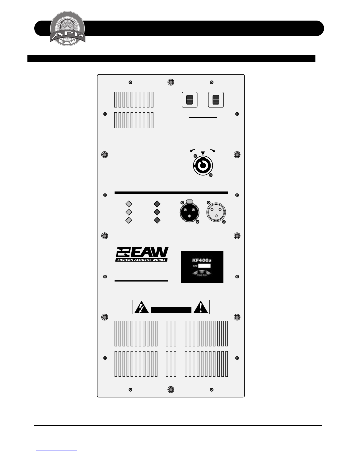
The AC power input connector shall be Neutrik PowerCon.
Auto-sensing power input shall operate from 95-125 VAC and
190-250 VAC. The audio input connector shall be a female
XLR (pin 2 hot) chassis-mount connector. A complementary
male XLR chassis-mount connector (pin 2 hot) shall be
provided for audio output (loop through). Five (5)
3-position flytracks (2 top and 3 bottom) shall be installed
in the enclosure. The front of the loudspeaker shall be
covered with a powder-coated perforated steel grill.
The self-powered, biamplified 3-way full range loudspeaker
shall be the EAW model KF400a.
SERVICE ITEMS
LF: Complete Cone Driver
EAW Part No. 804083
MF: Complete Cone Driver
EAW Part No. 804086
HF: Complete Compression Driver/Tweeter
EAW Part No. 803040
HF: Diaphragm Assembly
EAW Part No. 804023
Close Coupled Power™ Module: Complete Assembly
EAW Part No. 230002
Table of contents
Other EAW Speakers System manuals