manuals.online logo
Brands
  1. Home
  2. •
  3. Brands
  4. •
  5. EAW
  6. •
  7. Speakers System
  8. •
  9. EAW KF750 Series Parts list manual

EAW KF750 Series Parts list manual

Other manuals for KF750 Series

1

This manual suits for next models

2

Other EAW Speakers System manuals

EAW MK2299 User guide

EAW

EAW MK2299 User guide

EAW VB-125 User manual

EAW

EAW VB-125 User manual

EAW SM159z User manual

EAW

EAW SM159z User manual

EAW Cinema CB223X User manual

EAW

EAW Cinema CB223X User manual

EAW CR72i User manual

EAW

EAW CR72i User manual

EAW KF860 User manual

EAW

EAW KF860 User manual

EAW JF60 User manual

EAW

EAW JF60 User manual

EAW MK2196 User guide

EAW

EAW MK2196 User guide

EAW MK2399 User manual

EAW

EAW MK2399 User manual

EAW Cinema SB284C User manual

EAW

EAW Cinema SB284C User manual

EAW LA212 User manual

EAW

EAW LA212 User manual

EAW Virtural Array KF850ZR User manual

EAW

EAW Virtural Array KF850ZR User manual

EAW KF850EF User manual

EAW

EAW KF850EF User manual

EAW Cinema MC4972 User manual

EAW

EAW Cinema MC4972 User manual

EAW MK5199 User guide

EAW

EAW MK5199 User guide

EAW KF650z User manual

EAW

EAW KF650z User manual

EAW KF730 User guide

EAW

EAW KF730 User guide

EAW MC4973B User manual

EAW

EAW MC4973B User manual

EAW KF300i User manual

EAW

EAW KF300i User manual

EAW LS432 User manual

EAW

EAW LS432 User manual

EAW UB12Se User manual

EAW

EAW UB12Se User manual

EAW Cinema CB423M User manual

EAW

EAW Cinema CB423M User manual

EAW Cinema MC4972A User manual

EAW

EAW Cinema MC4972A User manual

EAW MS63 User guide

EAW

EAW MS63 User guide

Popular Speakers System manuals by other brands

JVC MX-KA3 - Mini Shelf System null

JVC

JVC MX-KA3 - Mini Shelf System null

JVC CA-MXK5R instructions

JVC

JVC CA-MXK5R instructions

LG NB4532B owner's manual

LG

LG NB4532B owner's manual

JVC CA-FSH100 instructions

JVC

JVC CA-FSH100 instructions

5Core Pro Series Operation manual

5Core

5Core Pro Series Operation manual

Lynx GXR-LA10A user manual

Lynx

Lynx GXR-LA10A user manual

iLive ITB066B user guide

iLive

iLive ITB066B user guide

RDX QuickStation 4 product manual

RDX

RDX QuickStation 4 product manual

Electro-Voice S-122 Specifications

Electro-Voice

Electro-Voice S-122 Specifications

Sven SPS-619 GOLD Operation manual

Sven

Sven SPS-619 GOLD Operation manual

Pioneer CS-7070 instruction manual

Pioneer

Pioneer CS-7070 instruction manual

Sondpex Active Speaker System and Digital Music... User manual and installation instructions

Sondpex

Sondpex Active Speaker System and Digital Music... User manual and installation instructions

JVC NX-PN7 instructions

JVC

JVC NX-PN7 instructions

Yamaha NX-A01 - Speaker Sys Product bulletin

Yamaha

Yamaha NX-A01 - Speaker Sys Product bulletin

SE Audiotechnik I-LINE manual

SE Audiotechnik

SE Audiotechnik I-LINE manual

Gemini WRX-843 Series user manual

Gemini

Gemini WRX-843 Series user manual

TCL 6100 Series user manual

TCL

TCL 6100 Series user manual

JBL gto6506c owner's manual

JBL

JBL gto6506c owner's manual

manuals.online logo
manuals.online logoBrands
  • About & Mission
  • Contact us
  • Privacy Policy
  • Terms and Conditions

Copyright 2025 Manuals.Online. All Rights Reserved.

The Laws of Physics | The Art of Listening
EAW’s KF700 Series
Touring Usage Guide
Since its inception, EAW has combined market feedback with top-level engineering to
prod ce a range of tility-driven tools that address the needs of the to ring so nd market.
Over the last few years, EAW Engineering has worked steadily to find techniq es that allow
typical sers to create lo dspeaker arrays that act as a single nit. Developing and
integrating the vario s lo dspeaker mod les in the KF850, KF860 and KF900 Series has
led s to new ways of looking at array b ilding that provide even coverage thro gho t
large ven es.
These years of R & D have res lted in the logical, step-by-step array-b ilding process
contained within this G ide. While we foc s here on KF700 Series arrays, the basic
approach applies to these other EAW array-oriented prod cts.
1
EAW’s KF700 Series
Touring Usage Guide
2 DETERMINE HORIZONTAL COVERAGE
The horizontal coverage angle of any ven e can be
readily determined thro gh inspection of its plan view.
Once the horizontal coverage req irement has been
determined, calc late the n mber of col mns
req ired to thoro ghly address the entire
ven e based on each col mn's horizontal
coverage pattern.
I – The Five Basic Steps of Array Building
Ven e sizes and styles vary dramatically. It is not ncommon for a concert to r to play a 1,000 seat cl b, a 3,000
seat theater and an 8,000 seat arena on s ccessive nights. Creating the right array for each ven e is vital to
maintaining consistency and establishing a tr e contin m of s ccess. O r experience has led s to develop
a five step approach to designing the appropriate array for any ven e.
1 DESIGN ARRAY COLUMNS
Design a single array col mn that will address each vertical a dience zone in a cross-section r nning from the stage
thro gh the center of the ven e to the rear-most seat. Be s re to factor in the array trim height. To seamlessly cover
each vertical zone (front, middle, rear, balcony, etc.) req ires that the system engineer properly apply the vario s
array mod les in his/her arsenal incl ding s bwoofers. This is the primary key to delivering a niform response to
the entire ven e.
2
alcony
Design an Array Column
Main Seating
Downfill
Subwoofers
Right & Left Clusters
5x 30° Module Each
Provide 150° Coverage
Seats Not Sold
Seats Not Sold
STAGE
150°150°
Determine Horizontal Coverage
3
3 IMPLEMENT SIGNAL PROCESSING
Mod le-specific array processing, c rrently s pported by most digital platforms, allows the ser to address coverage
of each vertical a dience zone independently (i.e. separate settings for long throw, main coverage and downfill
array mod les). This s ally does not req ire a separate processor channel for each row.
10x KF755 (inverted)
2 Processor Outputs* for upfill KF755's
20x KF750
3 Processor Outputs for main coverage KF750's
5x KF755
2 Processor Outputs for downfill KF755's
Independent Powering Capability per Row
(Seven Total Processor Outputs Control 35 Modules)
Powering and Processing for a Large KF700 Series Array
4 APPLY ARRAY SHADING (AS3D™)
AS3D array shading is a techniq e EAW Engineering developed to minimize destr ctive interaction between array
mod les and prod ce even coverage in three-space (three dimensions). AS3D req ires that the array amplification
be zoned in horizontal rows to permit implementation of s btle bandwidth and row dependent amplifier adj st-
ments. Array shading has a dramatic impact on the consistency of tonality thro gho t the ven e.
5 TWEAK
That is, adj st EQ to s it yo r taste. The first fo r steps of array b ilding sho ld provide the ser with niform
coverage thro gho t the ven e s ch that he can set EQ at the mix position with f ll confidence that each
adj stment has the same impact thro gho t the ven e.
Tweak with Confidence
The mix heard at FOH
is the mix everybody in the venue will hear
* Optimally, each row should see two separate processor outputs,but
the only difference between the settings would be a subtle,but impor-
tant,change in the signal delay. This can more cost-effectively be
achieved by splitting the outputs of a single processor and routing one
pair through an external delay.
4
II – KF700 Series Array Philosophy
Since we set o t to develop the KF700 Series for ease of se, we insisted that arrays designed to cover any ven e
co ld be flown q ickly, easily, and safely as a dead h ng cl ster. S ch a system wo ld save the ser both time and
money while providing his/her client with an aco stically consistent and aesthetically pleasing cl ster.
To f rther enhance tility, the KF700 Series ses a m lti-axial approach that creates compact mod les that provide
the high “Q” pattern control associated with m ch larger devices. Combined with the tightly packed, dead-h ng
nat re of the cl ster, this allows for maxim m co pling of array elements, providing tremendo s o tp t capability
thro gh the low and mid freq ency s bsections of the array.
Finally, KF700 Series arrays will provide niform coverage with relatively simplistic processing. We have developed
AS3D array shading to enhance array control and coverage witho t req iring additional DSP nits.
THE GOLDEN RULES
Both o r experience and ser feedback has led s to develop two Golden R les for KF700 Series sage. Following
these r les will not g arantee s ccess. However, not following them will definitely compromise array performance.
1
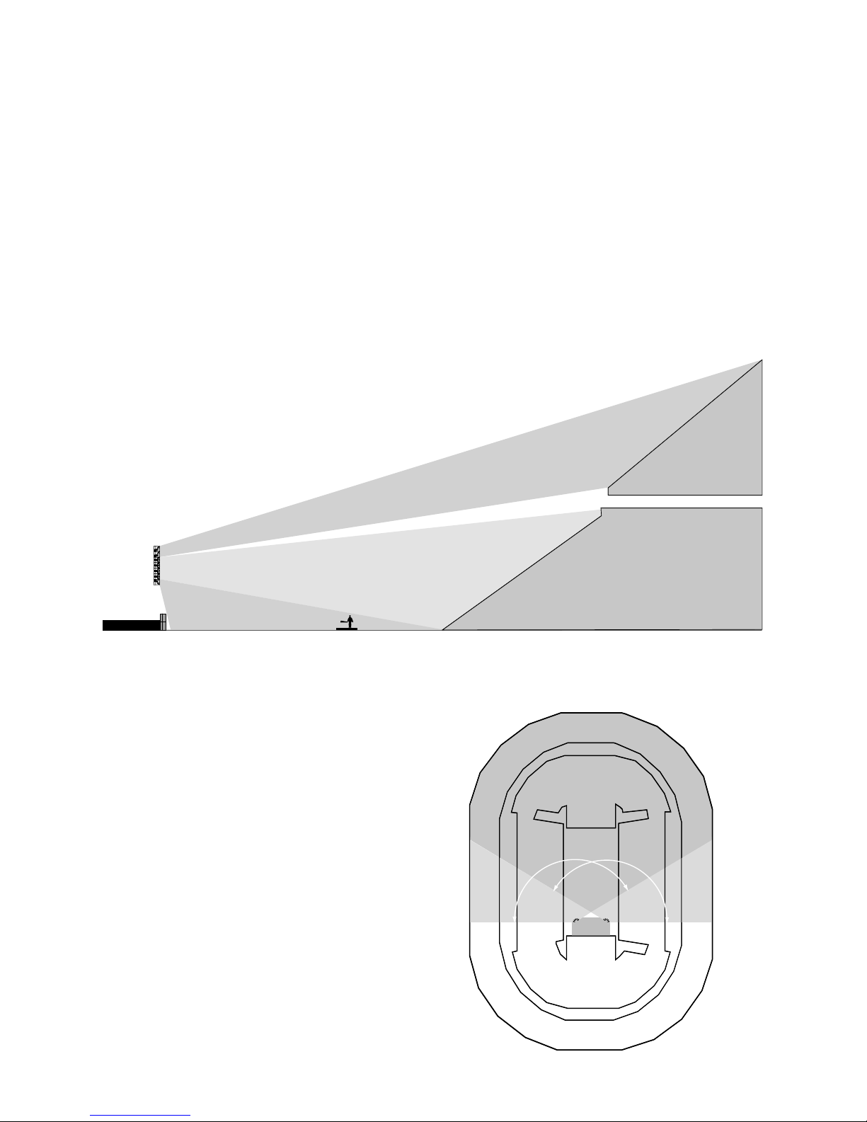
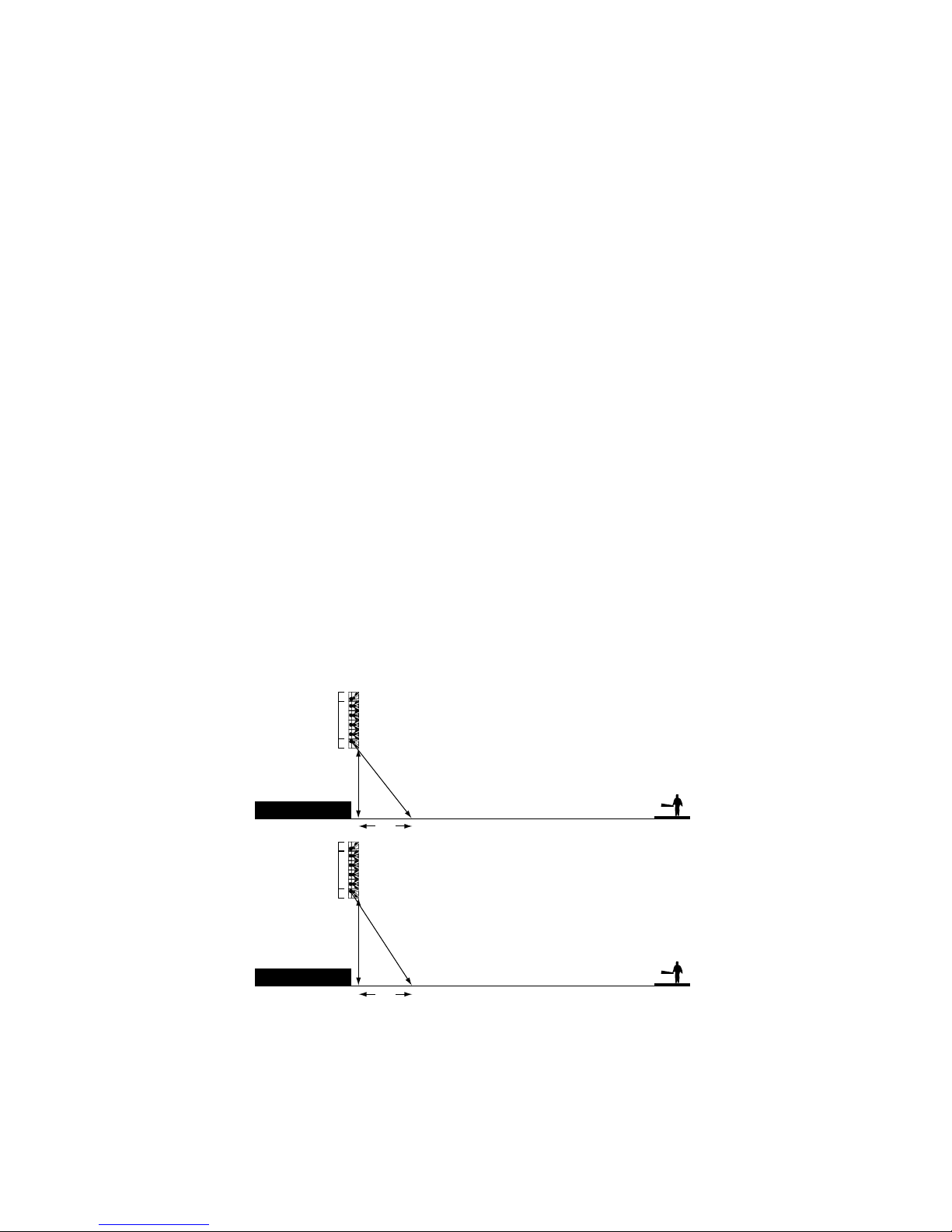
Never let an a dience member see a handle on a mod le in their primary cl ster. (It is alright if someone seated
ho se-right sees a handle on the ho se-left cl ster). The KF700 Series lo dspeakers provide a 30∞horizontal pat-
tern that drops off very rapidly o tside of this nominal angle. Since the physical angle of the enclos re is also 30∞,
if yo can see the handle, yo are o t of the pattern. The difference in performance will be a dible.
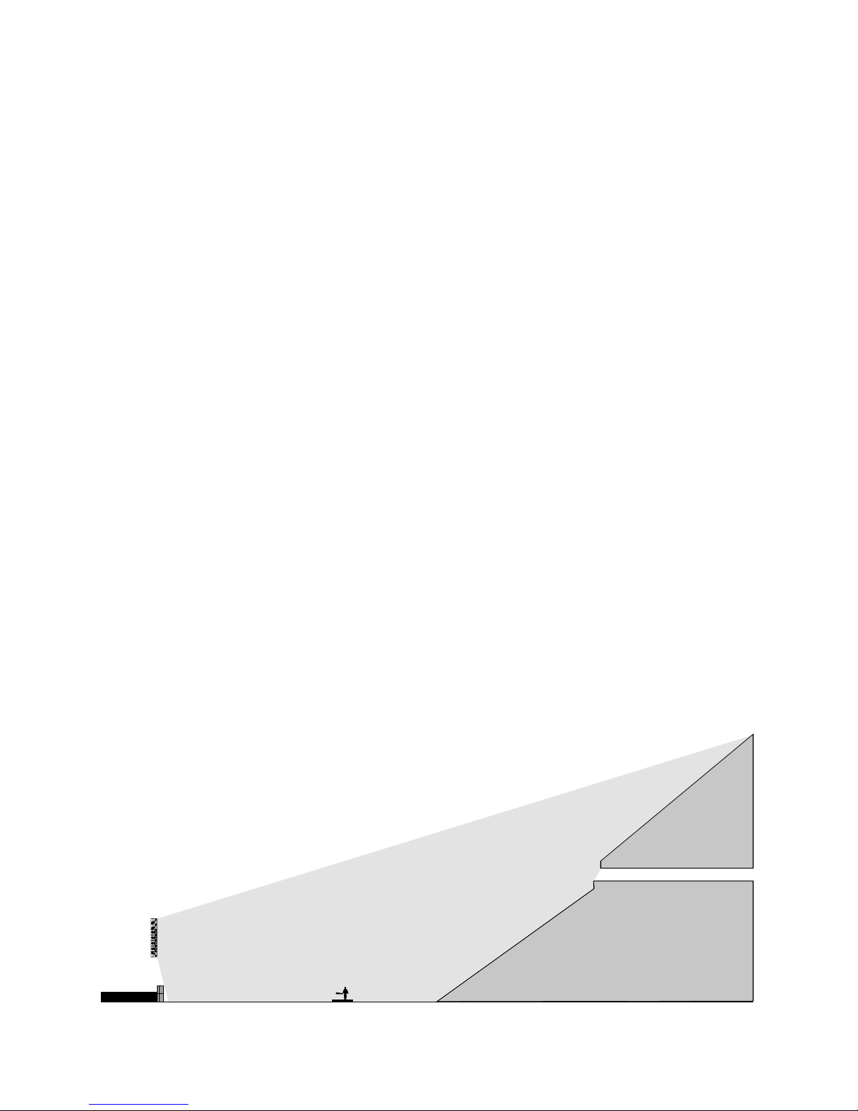
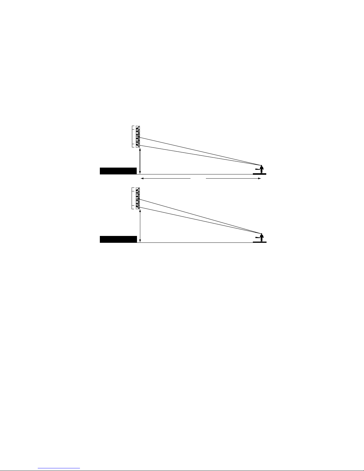
Provide separate processing for each row of KF755’s. Using m ltiple rows of KF755’s allows KF700 Series arrays to
work in a n mber of challenging ven es, b t each row of KF755's m st be processed independently in order to
achieve proper integration. (N. B. This req ires only two channels of o tp t per row in large arrays in which the
KF750's alone prod ce s fficient LF response.)
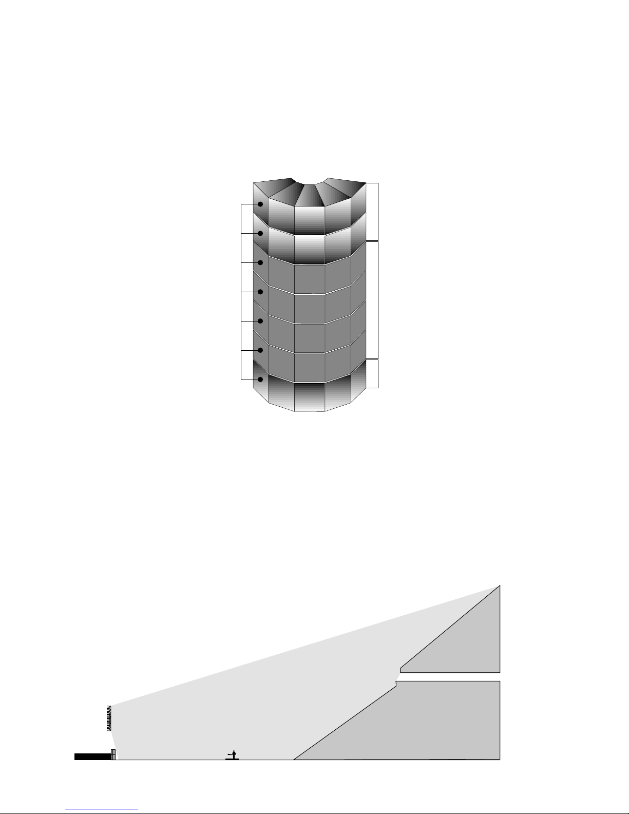
III – Building Arrays:Bandwidth by Bandwidth
The soon-to-be-released KF700 Series Owner’s
Man al provides information regarding the f nda-
mental design attrib tes of the mod les within the
series. These systems are designed to exhibit pre-
dictable behavior when arrayed, b t it is important to
realize that array behavior is not the same as mod le
behavior. In fact, when arrayed, the individ al
devices within a mod le combine with their co nter-
parts in adjacent mod les to achieve a different level
of performance that m st be addressed as a system. It
is vital to nderstand the nat re of this device cooper-
ation in order to consistently b ild and ltimately
t ne these high performance cl sters.
Distributed HF Horns MF Line Source LF Line Array
5
Multiple MF Arrivals
Multiple HF Arrivals Create
Too Much Low HF (1 – 2 kHz)
Array Performance Issues Addressed by andwidth
Too Much Low Mid (300 – 600 Hz)
Weak HF Response
LOW FREQUENCY LINE ARRAYS
The low freq ency components within an individ al KF750 array mod le behave as a t ned dipolar array, b t in a
large format cl ster the low freq ency devices co ple to behave as a line array (a col mn of closely spaced devices).
These LF line arrays provide tremendo s o tp t along the primary axis of a dead h ng cl ster, and their coverage
pattern mimics the conto rs of most ven es. As a res lt, the LF s bsection req ires little adj stment except incre-
mental level atten ation as additional mod les are employed.
MID FREQUENCY LINE SOURCES
The mid freq ency horn in a KF700 Series mod le occ pies the f ll frontal dimensions of the enclos re. As a res lt,
adjacent mod les (incl ding KF755’s) co ple to behave as a tr e line so rce that exhibits increased directivity with
increased size, providing high levels of pattern control thro gho t the operating bandwidth. Projection of lower
mid freq ency information is also improved to the point that low/mid energy in the long throw may need to be
atten ated to provide more spatial consistency.
The imp lse response of a line so rce is most notably infl enced by the edge events. That is, an imp lse response
meas rement reveals two distinct pper mid freq ency arrivals coming from the physical edges of the line so rce
(i.e. the top of the top mod le and the bottom of the bottom mod le). Th s at an observation point beneath the
cl ster the first meas red arrival comes from the lower line so rce edge while the second, noticeably later, arrival
comes from the topmost edge. These m ltiple arrivals in t rn prod ce comb filtering in the front rows of a typical
ven e which, fort nately, can be eliminated with appropriate AS3D array shading .
HIGH FREQUENCY DISTRI UTED SOURCES
The high freq ency horns in a KF700 Series array are not prone to co pling as they are physically separated and
behave as distrib ted so rces m ch like the behavior of KF850 arrays.
When sing KF755’s as down/front fill lo dspeakers, the mix position is typically provided with high freq ency
o tp t from the KF755’s as well as m ltiple rows of KF750’s. If the arrivals from the KF755's and the next row of
KF750’s are near one another in level, the bottom of the high freq ency operating range becomes dominant at
front-of-ho se position. However, implementing appropriate AS3D array shading will eliminate this b ild p of
1kHz to 2kHz energy at FOH.
In long throw applications, the air's absorption of HF energy significantly impacts response as the distance from the
so rce increases. Techniq es will be disc ssed later in this G ide that allow the ser to address this specific iss e.
The Laws of Physics | The Art of Listening
EAW’s KF700 Series
Touring Usage Guide
INTEGRATING MODULES INTO AN ARRAY COLUMN
6
4.3' difference in throw results in 1.32 d less output in the nearfield
Add 1.32 d additional downfill gain to compensate for 5' increased trimheight
Adding downfill gain to compensate for additional trim height
26.3'
30.6'
20'
25'
12'
12'
1x KF755 (inverted)
4x KF750
1x KF755
1x KF755 (inverted)
4x KF750
1x KF755
0 d
-1.32 d
I – Using KF750’s for Primary Coverage
As disc ssed in Section 1, array col mns are created based on a ven e’s cross-section. Nat rally, the overall depth of
the ven e will govern the n mber of KF750’s in the col mn with larger ven es req iring more KF750’s per col mn.
For basic g idelines on the q antity of KF750’s req ired per col mn in specific ven e types, see Section 4.
II – Using KF755’s for Downfill Coverage
When cl sters are flown, most ven es req ire downfill in order to effectively cover the front of the a dience. Since
the KF755 ses an asymmetrical m lti-axial design, it will provide downfill coverage from a deadh ng array.
Properly integrating KF755 downfill mod les with appropriate processing and AS3D techniq es will provide even
coverage to the front of the ven e witho t creating interference iss es in the transition area between KF755 and
KF750 coverage.
Dedicated downfill mod le processor settings* allow sers to integrate KF755’s into a KF750 cl ster witho t
modifying the KF750 processing. The nconventional settings that res lt will make a KF755 so nd tonally
nbalanced when listened to in the absence of a KF750 array above. This is entirely intentional and provides
for tonally transparent transition from downfill coverage to the primary cl ster.
IIa – Adjusting KF755 System Gain and System Delay
As the ser moves from ven e to ven e, (s)he need adj st only two critical KF755 parameters: system gain and
system delay, both of which vary with trim height and n mber of KF750's per col mn.
Defa lt KF755 gains are set for given KF750 q antities in the standard array processing. This gain however, m st be
adj sted as trim height varies. If the cl ster is flown higher than the defa lt setting’s ass mptions, the KF755 gain
m st be increased to compensate for increased throw and vice versa.
* Processor settings will be released in text format as part of the Touring Usage Guide.
7
All defa lt delay settings are config red to allow sers to fine-t ne delay at FOH. Downfill delay and gain can be
simply adj sted and t ned by ear. Coherent s mmation is a very a dible phenomenon. Aco stical analysis
systems, s ch as SIA-SMAART, aid in the ability to fine t ne these parameters. If FOH location and trim height are
typical and appropriate processing is being tilized, then KF755 integration sho ld be as simple as powering p.
III – Using SB750’s
Virt ally all pro a dio applications req ire s b bass reinforcement and a ratio of at least one SB750 per every two
KF700 array mod les is the r le of th mb. The SB750 offers sers the flexibility of stacking s bwoofers on the
gro nd or flying them with the array. Users can insert flown s bs as rows above and/or below the main array, or in
col mns along the off-stage side of the main array. (Inserting flown s bwoofers directly withing the main array is
not recommended.) Each location has benefits and trade-offs. Most ven es req ire a combination of locations for
optimal performance. In all cases, the s bwoofers m st be timed for coherent arrival in order to achieve
appropriate s mmation thro gho t a ven e.
IIIa – Groundstacking SB750’s
Many sers will choose to se SB750’s in a traditional gro ndstacked config ration. In addition to providing even
s b bass coverage thro gho t a ven e, this techniq e also provides maxim m s b bass impact in the front rows,
a q ality many fans have come to expect in high-energy live m sic performances.
1.169 msec - 0.931 msec = 0.238 msec
Therefore add 0.238msec of additional downfill delay to compensate for 5' of increased trim height
Adding downfill delay to compensate for additional trim height
20'
0.931msec arrival differential at FOH
1.169msec arrival differential at FOH
25'
100'
1x KF755 (inverted)
4x KF750
1x KF755
1x KF755 (inverted)
4x KF750
1x KF755
Defa lt processor settings delay the KF755’s back to the aco stic origin of the KF750 col mn. As more KF750’s are
sed per cl ster, the apparent origin of the col mn moves pward and increased KF755 system delay is added with
each row of KF750’s.
Defa lt processor settings apply system delay to KF755 downfill mod les based pon ass med typical trim heights
and FOH locations as described in Section 4. If FOH is atypically close, this delay sho ld be increased. If FOH is
atypically distant, the system delay sho ld be red ced.