EAW KF760 Quick start guide

KF760 SERIES
RIGGING GUIDE
KF760 Series Rigging Procedures PRELIMINARY DRAFT -- 21 Aug 01
KF760 Series Rigging Procedures PRELIMINARY DRAFT -- 21 Aug 01 P ge 1 of 29
KF760 SERIES RIGGING GUIDE
1 RIGGING INFORMATION
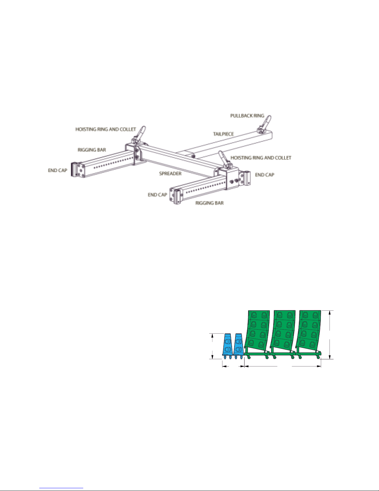
1.1 FLY-BAR PHYSICAL FEATURES
1.2 PALLETS
1.2.1 KF760 Palle :
This p llet holds four KF760s tight-p cked. This provides fl t top surf ce for double deck truck p ck.
The c ster positions re djust ble to fit different truck r mp widths. Position the c sters so they re the
s me dist nces from the outside edges of the p llet.
The c sters re secured to the p llet by remov ble long connecting pin (see section 1.3). Remove the
pin nd repositioning the c sters s needed. Ensure th t the connecting pins extend fully through the
holes nd re fully locked.
The c sters re repl ce ble llowing use of different
types of c sters or wheel m teri ls or wheel sizes s
needed for the p rticul r conditions of use.
1.2.2 KF761 Palle :
This p llet holds one KF761 f ce down for tr nsport
The c ster positions re djust ble to fit different truck
r mp widths. Position the c sters so they re the s me dist nces from the outside edges of the p llet.
The c sters re secured to the p llet by remov ble long connecting pin (see section 1.3). Remove the
pin nd repositioning the c sters s needed. Ensure th t the connecting pins extend fully through the
holes nd re fully locked.
The c sters re repl ce ble llowing use of different types of c sters or wheel m teri ls or wheel sizes
s needed for the p rticul r conditions of use.
112"
32"
71"
37"

KF760 Series Rigging Procedures PRELIMINARY DRAFT -- 21 Aug 01
KF760 Series Rigging Procedures PRELIMINARY DRAFT -- 21 Aug 01 P ge 2 of 29
1.3 CONNECTING PINS
Two types of connecting pins re used with KF760 rr y. The 1-1/4 inch or short connecting pins re
used for ll enclosure to enclosure nd enclosure to Fly-B r connections. The 4 inch or long connecting
pins re used to connect Fly-B r components together nd secure the c sters to the c ster p llets. Both
types re single cting, double b ll pins with minimum double she r strength of 20,000 lb / 9,000 kg.
Shaf Diame er Leng h * Designa ion
3/8 in 4 in Short
3/8 in 1-1/4 in Long
* Me sured from shoulder to the b lls
CAUTION: Inser all enclosure connec ing pins from he inside of he Hinge Tubes. Inser ing he
connec ing pins from he ou side of he enclosure in o he Hinge Tubes can and will resul in
jammed pins. This is because he hole dimensions and clearances are no designed for inser ing
he pins in his direc ion.
1.4 RIGGING PREPARATION
It is very import nt to properly prep re the Fly-B r, enclosures, nd T il B r or Pull-B ck B r for rigging.
If incorrectly configured beforeh nd, it will be more difficult nd less efficient to rig n rr y nd required
p rts m y get lost. In the following checklist, the loc tions of the connecting pins re where the pins
should norm lly be locked in for stor ge or tr nsport tion in nticip tion of rigging n rr y. Following
this scen rio, connecting pins will lw ys be v il ble where they re needed for the purposes listed.
The only exceptions re the two extr short connecting pins shipped with e ch enclosure used for locking
the hinges when the Pull-B ck B r is used. These re norm lly stored loose .
1.4.1 KF760 and KF761 Enclosures:
1. Le ve short connecting pin in the bottom hole of e ch Hinge Tube on e ch enclosure.
Use these to:
Att ch n under hung KF760 or KF761 by eng ging its four hinges.
Att ch KF760 on p llet to the one below it by eng ging its four hinges.
2. There re two ddition l connecting pins intended for locking the hinges provided with the KF760s nd
KF761s. Do not store these in their rigging bec use the only pl ces to put them will be in the w y when
rigging. Store these pins loose where you will not lose them.
3. Do not le ve connecting pins in ny other holes other th n s in #1.
1.4.2 Fly-Bar:
1. Le ve short connecting pin in the bottom hole of e ch Hinge Tube on the Fly-B r. Use these to:
Att ch the top KF760 or KF761 enclosure of the rr y to the Fly-B r.
2. Le ve four long connecting pins in e ch Hoisting Ring Collet. Note: these pins norm lly would be in
use if the Fly-B r were left ssembled. Use these to:
Att ch the Hoisting Ring Collet to the Rigging B rs.
Att ch the Hoisting Ring Collet to the Spre der.
1.4.3 Assembled Fly-Bar Lef Connec ed o Top of a KF760 for Transpor a ion and S orage
1. Lock the top enclosure s four hinges in their extended (up) position using the top hole in e ch Hinge
Tube nd the bottom hole in e ch hinge. Use four short connecting pins for this. This will keep the hinges
from dropping into the Hinge Tube nd thus keep the Fly-B r from cont cting the top enclosure.

KF760 Series Rigging Procedures PRELIMINARY DRAFT -- 21 Aug 01
KF760 Series Rigging Procedures PRELIMINARY DRAFT -- 21 Aug 01 P ge 3 of 29
2. Secure the Fly-B r to the top enclosure with four short connecting pins, one in e ch of the Fly-B r s
four Hinge Tubes, tt ching it through the hinges of the top enclosure.
1.4.4 Tail Bar:
Le ve two long connecting pins in the T il B r for tt ching it to the Spre der.
1.4.5 Pull-Back Bar:
No connecting pins st y with this p rt. If properly prep red for use (see section 1.4.1), there should be
two short connecting pins v il ble in the bottom of ny enclosure s Hinge Tubes for tt ching the Pull-
B ck B r to the bottom enclosure of the rr y.
1.5 TO PULL-BACK OR NOT TO PULL-BACK
The KF760 Wiz rd will show where the Spre der B r must be positioned for the correct down tilt ngle for
the entire rr y. If this ngle is beyond wh t is possible by positioning the Spre der B r, the Wiz rd will
indic ted pull-b ck is needed. This requires n ddition l pick point nd ch in motor.
1.5.1 Two pull-back me hods:
1. T il-B r — This will pull the top re r of the rr y up to chieve the correct h ng ngle.
Adv nt ges: The ch in motors re ll t essenti lly the s me height. When running ll three
motors, the lift dist nces will be bout the s me.
Dis dv nt ges: The pull-b ck motor will h ve much gre ter lo d on it th n when using the Pull-
B ck B r. The number of degrees of pull-b ck is limited to ±15 degrees.
2. Pull-B ck B r — This will pull up on the bottom re r of the rr y to chieve the correct h ng ngle
Adv nt ges: The pull-b ck motor will h ve much less lo d on it th n when using the T il-piece.
The number of degrees of pull-b ck is not limited.
Dis dv nt ge: The pull-b ck motor rides ne r the bottom of the rr y. When running ll three
motors, the pull-b ck motor will l g behind in lift dist nce.
2 RIGGING PROCEDURES
The following rigging procedure is the recommended method for ssembling nd dis ssembling KF760
rr y. While it is possible to use other techniques th n the ones shown, EAW recommends you use the
procedures det iled below.
While these rigging procedures m y seem complex, in re lity they re quite e sy to perform. During the
photogr phy session for the pictures cont ined herein, the rr y depicted in the procedures w s lo ded in
nd lo ded out sever l times. E ch time, the complete lo d-in or lo d-out procedure took pproxim tely
six minutes s performed by two, non-profession l personnel.
The rigging sequences show the steps for lo d in nd lo d out of n eight over two rr y. This me ns
eight KF760s re under hung with two KF761s. Depending on the number nd types of enclosures in
KF760 rr y, the sequence you need m y differ. However, the specific det ils of the steps for rigging
KF760s or KF761s will be the s me.
WARNING: During he rigging procedure, here will be considerable weigh being moved and lif ed
overhead. Depending on he array configura ion, he array may end o swing forward or
backwards as addi ional enclosures are added and as he array s weigh is aken by he chain
mo ors. Personnel near he array mus be aware ha his can and will happen and should
posi ion hemselves appropria ely o preven injury or dea h.

KF760 Series Rigging Procedures PRELIMINARY DRAFT -- 21 Aug 01
KF760 Series Rigging Procedures PRELIMINARY DRAFT -- 21 Aug 01 P ge 4 of 29
WARNING: The array should always be level side- o-side. This should be moni ored and adjus ed
as needed hroughou he rigging procedure o preven he array from swinging sideways as he
array s weigh is being aken by he chain mo ors. Personnel near he array mus be aware ha
his can and will happen and should posi ion hemselves appropria ely o preven injury or dea h.
CAUTION: During he following procedures, inser all shor connec ing pins from he inside of he
Hinge Tubes. Inser ing he pins from he ou side of he enclosure in o he Hinge Tubes can and
will resul in jammed pins. This is because he hole dimensions and clearances are no designed
for inser ing he pins in his direc ion.
IMPORTANT NOTE: With the exception of connecting pins used to lock the hinges, connecting pins
should be inserted into one of the bottom holes of e ch enclosure s four hinge tubes. This is true whether
the enclosure h s nything tt ched bene th it ( nother enclosure or p llet) or not. F ilure to follow
this rule will result in either lost connecting pins or connecting pins not v il ble when nd where they re
needed during lo d-in nd lo d out procedures.
IMPORTANT NOTE FOR SPLAYED ENCLOSURES: Two of the six short connecting pins supplied with
e ch KF760 nd KF761 re intended s hinge locking pins when the re r of the enclosures re spl yed
nd the Pull-B ck B r is used. Norm lly gr vity keeps the re rs of spl yed enclosures p rt, thus
m int ining the spl y. When Pull-B ck B r is used, it cre tes n upw rd force on the re r of the
enclosures, tending to push the re rs of spl yed enclosures together, thus coll psing the spl y.
The solution is to lock the hinge in the top of the bottom enclosure between ny two spl yed enclosures.
To do this, insert connecting pin into the top hole of the e ch re r Hinge Tube nd through the bottom
of the hinge. This prevents the hinge from moving b ck down into its own Hinge Tube when n upw rd
force is pplied to the re r of the enclosure. When enclosures re tight-p cked using the Pull-B ck b r,
the hinge locking pin is not needed.
2.1 PICK POINTS
Est blish nd rig the two pick points for the rr y with ch in motors r ted for the lo d.
If pull b ck is used, est blish nd rig three pick points with ch in motors r ted for the lo d.
2.2 FLY-BAR ASSEMBLY
1. The Fly-B r is ssembled by tt ching the Spre der to the Rigging B rs. Use two long connecting
pins t e ch end of the Spre der to tt ch it to the Hoisting Ring collets. If the pull-b ck T il B r is to be
used, insert the T il B r rm into the sleeve in the center of the Spre der nd secure with two long
connecting pins.
2. The front-to-b ck Spre der position is determined by using the KF760 Wiz rd softw re. Position the
Spre der B r s indic ted by the Wiz rd.
3. Att ch the Fly-b r to the ch in motors using the two hoisting rings on the Rigging B r.
Ensure the Hoisting Ring Collets re tt ched to the Rigging B r with two long connecting pins e ch.
Ensure the Spre der is tt ched to the Hoisting Ring Collets with two long connecting pins t e ch end.
2.3 LOAD IN
2.3.1 Firs KF760 Palle

KF760 Series Rigging Procedures PRELIMINARY DRAFT -- 21 Aug 01
KF760 Series Rigging Procedures PRELIMINARY DRAFT -- 21 Aug 01 P ge 5 of 29
1. Bring in the first p llet of four KF760s nd position it under the ch in motors.
2. Lower the ch in motors for tt chment ot the Fly-B r Hoist Rings.
3. If the Fly-B r w s tr nsported tt ched to p lleted KF760s then tt ch the ch in motors to the Fly-B r
nd skip the next steps.
4. If the Fly-B r w s tr nsported un- tt ched from KF760 p llet then tt ch the ch in motors to the
ssembled Fly-B r nd perform the next two steps (not shown):
1. L nd the Fly-B r on top enclosures so the weight is off the ch in motors.
KF760 Series Rigging Procedures PRELIMINARY DRAFT -- 21 Aug 01
KF760 Series Rigging Procedures PRELIMINARY DRAFT -- 21 Aug 01 P ge 6 of 29
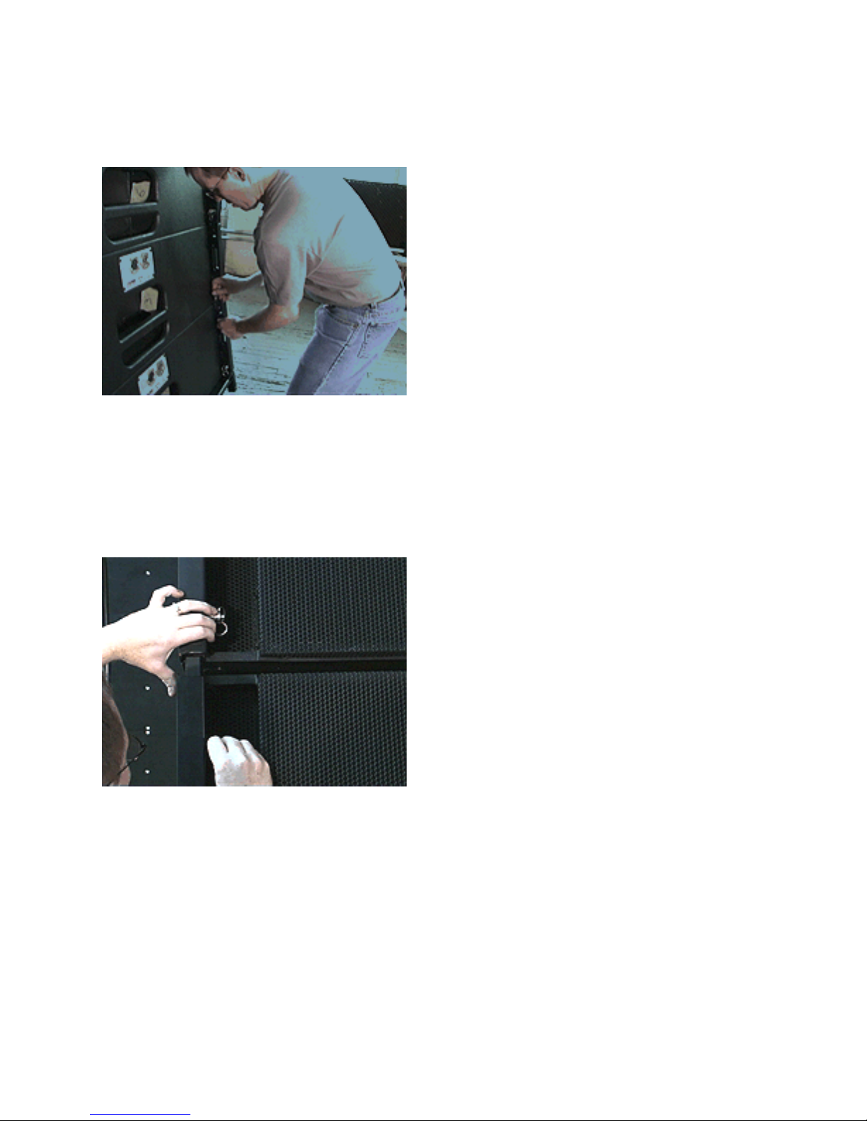
2. Push up e ch of four hinges on top enclosure into fly-b r Hinge Tubes nd pin to the Fly-B r
Hinge Tube with the short connecting pins. Ensure th t pins extend fully through the hinges nd
Hinge Tubes nd re fully locked.
5. Adjust the re r hinges between e ch two enclosures for the desired re r spl y ngle by positioning
e ch of the two hinges into the Hinge Tubes of the enclosure bove. Use the short connecting pin to
eng ge the hinge using the ppropri te one of the three holes provided in the e ch upper enclosure
Hinge Tube.
Top hole = tight p cked
Center Hole = 1-1/2¡ spl y
Bottom hole = 3¡ spl y
Ensure th t the connecting pins extend fully through the hinges nd Hinge Tubes nd re fully locked.
5. Ensure th t ll hinges on the front of the enclosures re positioned nd pinned so th t enclosure fronts
will be tight-p cked when flown.
6. Pull-B ck B r (not shown):
If the Pull-B ck B r is to be used, the re r hinges on ny spl yed enclosures must be locked in position to
prevent the hinges from moving down into their own Hinge Tubes when the pull-b ck force is pplied. To
lock the hinges, insert connecting pin into the top hole of the e ch re r Hinge Tube nd through the
bottom of the hinge. This prevents the hinge from moving b ck down into its own Hinge Tube when n
upw rd force is pplied to the re r of the enclosure. When enclosures re tight-p cked, the hinge locking
pin is not needed.
KF760 Series Rigging Procedures PRELIMINARY DRAFT -- 21 Aug 01
KF760 Series Rigging Procedures PRELIMINARY DRAFT -- 21 Aug 01 P ge 7 of 29
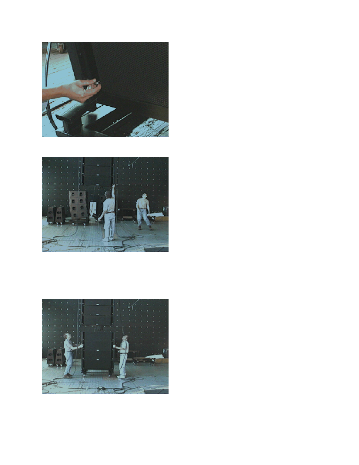
7. Disconnect p llet from the bottom enclosure by removing the four short connecting pins. Insert the
four connecting pins in the bottom enclosure Hinge Tubes.
8. Fly the first four enclosures to n ppropri te working height for the next step nd push the KF760
p llet side. L ter this will be used s KF761 rigging id.
NOTE: When rr y is flown, the re r enclosure spl ys will utom tic lly open up to the desired ngle.
2.3.2 Second And Subsequen KF760 Palle s
1. Bring in the second p llet of KF760s nd position it under the flown rr y.

KF760 Series Rigging Procedures PRELIMINARY DRAFT -- 21 Aug 01
KF760 Series Rigging Procedures PRELIMINARY DRAFT -- 21 Aug 01 P ge 8 of 29
2. Adjust the re r hinges between e ch enclosure for the desired re r spl y ngle by sliding the e ch of
the four hinges into the Hinge Tubes of the upper enclosure. Use the short connecting pin to eng ge the
hinge using the ppropri te one of the three holes provided in the e ch upper enclosure Hinge Tube.
Top hole = tight p cked
Center Hole = 1-1/2¡ spl y
Bottom hole = 3¡ spl y
Ensure th t pins extend fully through the hinges nd Hinge Tubes nd re fully locked.
3. If Using the Pull-B ck B r (not shown):
If the Pull-B ck B r is to be used, the re r hinges on ny spl yed enclosures must be locked in position to
prevent the hinges from moving down into their own Hinge Tubes when the pull-b ck force is pplied.
To lock the hinges, insert connecting pin into the top hole of the e ch re r Hinge Tube nd through the
bottom of the hinge. This prevents the hinge from moving b ck down into its own Hinge Tube when n
upw rd force is pplied to the re r of the enclosure. When enclosures re tight-p cked, the hinge locking
pin is not needed.
4. Ensure th t ll hinges on the front of the enclosures re positioned nd locked so th t enclosure fronts
will be tight-p cked when flown.

KF760 Series Rigging Procedures PRELIMINARY DRAFT -- 21 Aug 01
KF760 Series Rigging Procedures PRELIMINARY DRAFT -- 21 Aug 01 P ge 9 of 29
5. Disconnect p llet from the front of the bottom enclosure by removing the four short connecting pins.
Insert the four connecting pins in the bottom enclosure Hinge Tubes.
6. Bring in flown enclosures to within bout 1in / 25 cm of the front top of p lleted enclosures.
7. Slide up the two front hinges of the topmost p lleted enclosure into bottommost flown enclosure nd
tempor rily pin the hinge to the topmost p lleted enclosure s Hinge Tubes.
NOTE: This ligns the KF760 with the flown enclosure bove it for the next step.
Other manuals for KF760
4
This manual suits for next models
1
Other EAW Speakers System manuals


