EAW N T L 7 2 0 User manual

NTL720 LOUDSPEAKER
OWNER’S MANUAL

ii

1 SAFETY PRECAUTIONS - READ THIS FIRST
1.1 Safety Instructions
Read and heed all warnings and safety instructions in the accompanying "EAW Loudspeaker Owner’s
Manual"beforeusingthisproduct.Failuretofollowthisprecautionmayresultindamage,injury, or death.
WARNING: The loudspeaker is supplied with an AC mains power cable. Depending on the
voltage model ordered, this cable is configured with the most common AC mains connector for
that voltage. If the connector is not compatible with the local AC mains receptacle, employ a
licensed electrician to re-configure the cable with the proper connector. Ensure that theAC power
supply has a properly grounded safety ground. Failure to follow this warning could cause
damage, injury, or death.
1 CONSIGNES DE SÉCURITÉ - À LIRE EN PREMIER
1.1 Instructions Relative à la Sécurité
Lisez et respectez toutes les consignes de sécurité et les mises en garde fournies dans le manuel des
enceintes EAW avant d'utiliser ce produit. Le non-respect de ces consignes et mises en garde peut
entraîner des dommages aux équipements et des accidents aux personnes pouvant être fatals.
ATTENTION: L'enceinte est fournie avec un cordon secteur. Selon la tension du modèle
commandé, ce câble est fourni avec la fiche la plus communément utilisée avec cette tension. Si
la fiche n'est pas compatible avec les prises secteur de votre région, faites appel à un électricien
agréé pour modifier le cordon secteur en fonction du format local. Vérifiez que la fiche secteur
dispose d'une mise à la terre. Le non-respect de la mise à la terre peut entraîner des dommages
aux équipements et des accidents aux personnes pouvant être fatals.
1. PRECAUZIONI DI SICUREZZA - DA LEGGERE PER
PRIMO
1.1 Norme di Sicurezza
Primadi procedere con l'utilizzo del prodotto, leggere erispettare ogni avvertenza e norma di sicurezza
riportata nel "Manuale EAW Loudspeaker". Il mancato rispetto di ogni precauzione può causare danni
all'apparecchiatura, nonché infortuni alle persone o la morte.
ATTENZIONE: Il diffusore è completo di cavo d'alimentazione ac fornito in dotazione. In base
la voltaggio del modello di diffusore acquistato, il cavo è configurato con il connettore ac più
adeguato. Nel caso in cui il connettore non sia compatibile con le prese di corrente adottate
nell'area d'impiego, rivolgersi ad un elettricista qualificato per ri-configurare il cavo con il
iii
NTL720 Loudspeaker Owner’s Manual
Congratulations on the purchase of your new EAW loudspeaker. You now own one of the finest
professional audio products available - the result of exceptional engineering and meticulous
craftsmanship. Please read these instructions to get the maximum performance from your new
loudspeaker.

connettore più appropriato. Assicurarsi che la presa di corrente sia adeguatamente collegata a
terra. Il mancato rispetto di tali norme può causare danni all'apparecchiatura, nonché infortuni
alle persone o la morte.
1. PRECAUCIONES DE SEGURIDAD - LEA ESTO PRIMERO
1.1 Instrucciones de Securidad
Lea y observe todos los avisos e instrucciones de seguridad que aparecen en el "Manual de altavoces
EAW" adjunto antes de usar este aparato. El no observar esta precaución puede dar lugar a averías en el
aparato, daños en las personas o incluso la muerte.
PRECAUCION: El altavoz viene de fábrica con un cable de corriente. Dependiendo del voltaje
que use el modelo solicitado, este cable estará configurado con el enchufe más habitual para ese
tipo de corriente. Si ese enchufe no es compatible con su salida de corriente, contacte con un
electricista profesional para que cambie el enchufe del cable por el tipo adecuado. Asegúrese de
que la salida de corriente tenga una conexión a tierra adecuada. El no observar esta advertencia
puede dar lugar a averías en el aparato, daños en las personas o incluso la muerte.
1. SICHERHEITSHINWEISE - LESEN SIE DIESEN
ABSCHNITT ZUERST
1.1 Sicherheitsanweisungen
Lesen und beachten Sie alle Warnungen und Sicherheitsanweisungen der mitgelieferten "EAW
Lautsprecher Bedienungsanleitung" vor der Benutzung des Produkts. Nichtbeachtung dieser Hinweise
können möglicherweise zu Schäden am Equipment oder zu Verletzungen bzw. zum Tod von Personen
führen.
WARNUNG: Der Lautsprecher wird mit einem Netzkabel geliefert.Abhängig von der jeweiligen
Netzspannung wird das Kabel mit dem für die jeweilige Netzspannung gängigsten Netzstecker
ausgeliefert. Sollte der Netzstecker nicht in Ihre Netzsteckdose passen, dann lassen Sie von
einem zugelassenen Elektrobetrieb einen passenden Netzstecker montieren. Stellen Sie sicher,
dass der Schutzkontakt der Netzsteckdose einen guten Kontakt zur Erde hat. Nichtbeachtung
dieser Hinweise können möglicherweise zu Schäden am Equipment oder zu Verletzungen bzw.
zum Tod von Personen führen.
iv

1.2 EC Declaration of Conformity
Manufacturer: EasternAcoustic Works — USA
Declares that the following product(s) have been tested and passed all relevant requirements as
described below by the appropriate European Directives as they apply to ProfessionalAudio Products.
Product Model: NTL720
Product Description: Self-powered loudspeaker
Safety Directive(s): EN 60065-2002
EMC Directive(s): EN 55103-1 (Radiated/Conducted Emissions)
EN 55103-2 (Radiated/Conducted Immunity)
2004/108/EEC Directive
Low Voltage Directive: 72/23/EEC
Markings Directive: 93/68/EEC
The Technical Report/File is maintained at:
LOUD Technologies Inc.
16220 Wood-Red Road NE
Woodinville, WA98072 USA
Authorized Representative: Tel: +1 425 892 6500
Kevin Cyrus Tel: +1 866 858 5832
Director of Compliance Fax: +1 425 487 4337
LOUD Technologies Inc. e-mail: info@eaw.com
Issued: February, 2008
1.3 FCC Compliance
This equipment has been tested and found to comply with the limits for a Class A digital device,
pursuant to Part 15 of the FCC Rules. These limits are designed to provide reasonable protection
against harmful interference when the equipment is operated in a commercial environment. This
equipment generates, uses, and can radiate radio frequency energy and, if not installed and used in
accordance with the instruction manual, may cause harmful interference to radio communications.
Operation of this equipment in a residential area is likely to cause harmful interference in which case
the user will be required to correct the interference at his own expense.
CAUTION: Changes or modifications not expressly approved by LOUD Technologies could void the
user's authority to operate the equipment.
Correct disposal of this product. This symbol indicates that this product should not be
disposed of with your household waste, according to the WEEE Directive (2002/96/EC)
and your national law. This product should be handed over to an authorized collection site
for recycling waste electrical and electronic equipment (EEE). Improper handling of this
type of waste could have a possible negative impact on the environment and human health
due to potentially hazardous substances that are generally associated with EEE. At the
same time, your cooperation in the correct disposal of this product will contribute to the
effective usage of natural resources. For more information about where you can drop off your waste
equipment for recycling, please contact your local city office, waste authority, or your household waste
disposal service.
v

CONTENTS
1 SAFETY PRECAUTIONS - READ THIS FIRST . . . . . . . . . . . . . . . . . . . . . . . . . . . . . . . . . . . . . . . . . . . . . . .iii
1.1 Safety Instructions . . . . . . . . . . . . . . . . . . . . . . . . . . . . . . . . . . . . . . . . . . . . . . . . . . . . . . . . . . . . . . . . . . . . . .iii
1 CONSIGNES DE SÉCURITÉ - À LIRE EN PREMIER . . . . . . . . . . . . . . . . . . . . . . . . . . . . . . . . . . . . . . . . . .iii
1.1 Instructions Relative à la Sécurité . . . . . . . . . . . . . . . . . . . . . . . . . . . . . . . . . . . . . . . . . . . . . . . . . . . . . . . . . .iii
1. PRECAUZIONI DI SICUREZZA - DA LEGGERE PER PRIMO . . . . . . . . . . . . . . . . . . . . . . . . . . . . . . . . . . .iii
1.1 Norme di Sicurezza . . . . . . . . . . . . . . . . . . . . . . . . . . . . . . . . . . . . . . . . . . . . . . . . . . . . . . . . . . . . . . . . . . . . .iii
1. PRECAUCIONES DE SEGURIDAD - LEA ESTO PRIMERO . . . . . . . . . . . . . . . . . . . . . . . . . . . . . . . . . . . .iv
1.1 Instrucciones de Securidad . . . . . . . . . . . . . . . . . . . . . . . . . . . . . . . . . . . . . . . . . . . . . . . . . . . . . . . . . . . . . . .iv
1. SICHERHEITSHINWEISE - LESEN SIE DIESEN ABSCHNITT ZUERST . . . . . . . . . . . . . . . . . . . . . . . . . .iv
1.1 Sicherheitsanweisungen . . . . . . . . . . . . . . . . . . . . . . . . . . . . . . . . . . . . . . . . . . . . . . . . . . . . . . . . . . . . . . . . . .iv
1.2 EC Declaration of Conformity . . . . . . . . . . . . . . . . . . . . . . . . . . . . . . . . . . . . . . . . . . . . . . . . . . . . . . . . . . . . . . .v
1.3 FCC Compliance . . . . . . . . . . . . . . . . . . . . . . . . . . . . . . . . . . . . . . . . . . . . . . . . . . . . . . . . . . . . . . . . . . . . . . . . .v
CONTENTS . . . . . . . . . . . . . . . . . . . . . . . . . . . . . . . . . . . . . . . . . . . . . . . . . . . . . . . . . . . . . . . . . . . . . . . . . . . . .vi
2 UNPACKING . . . . . . . . . . . . . . . . . . . . . . . . . . . . . . . . . . . . . . . . . . . . . . . . . . . . . . . . . . . . . . . . . . . . . . . . . . . .1
2.1 Contents . . . . . . . . . . . . . . . . . . . . . . . . . . . . . . . . . . . . . . . . . . . . . . . . . . . . . . . . . . . . . . . . . . . . . . . . . . . . . .1
3 QUICK START . . . . . . . . . . . . . . . . . . . . . . . . . . . . . . . . . . . . . . . . . . . . . . . . . . . . . . . . . . . . . . . . . . . . . . . . . .2
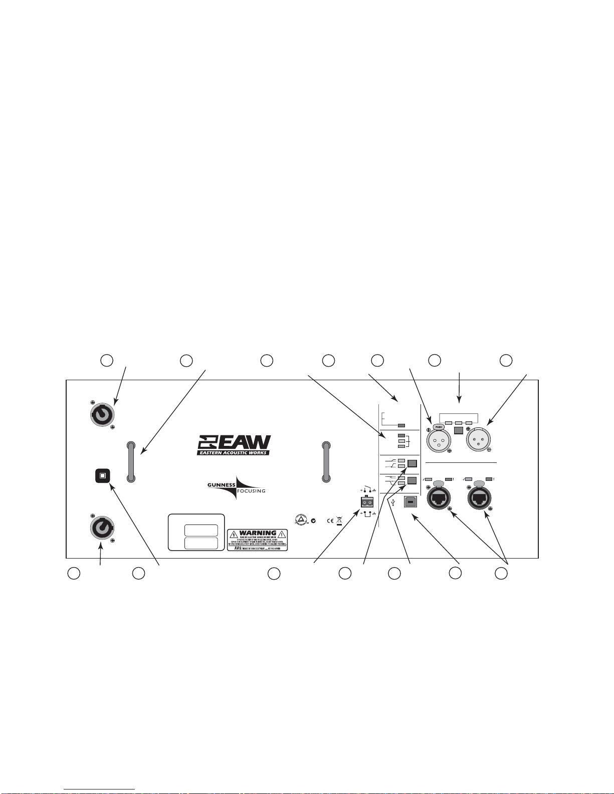
3.1 Rear Panel Connectors and Controls . . . . . . . . . . . . . . . . . . . . . . . . . . . . . . . . . . . . . . . . . . . . . . . . . . . . . . . .2
3.2 Initial Control Settings . . . . . . . . . . . . . . . . . . . . . . . . . . . . . . . . . . . . . . . . . . . . . . . . . . . . . . . . . . . . . . . . . .3
3.3 Audio Connection . . . . . . . . . . . . . . . . . . . . . . . . . . . . . . . . . . . . . . . . . . . . . . . . . . . . . . . . . . . . . . . . . . . . . .3
3.4 AC Mains Connection . . . . . . . . . . . . . . . . . . . . . . . . . . . . . . . . . . . . . . . . . . . . . . . . . . . . . . . . . . . . . . . . . . .3
3.5 Adjusting the Output Level . . . . . . . . . . . . . . . . . . . . . . . . . . . . . . . . . . . . . . . . . . . . . . . . . . . . . . . . . . . . . . .3
4 OVERVIEW . . . . . . . . . . . . . . . . . . . . . . . . . . . . . . . . . . . . . . . . . . . . . . . . . . . . . . . . . . . . . . . . . . . . . . . . . . . . .4
4.1 Introduction . . . . . . . . . . . . . . . . . . . . . . . . . . . . . . . . . . . . . . . . . . . . . . . . . . . . . . . . . . . . . . . . . . . . . . . . . . .4
4.2 Description . . . . . . . . . . . . . . . . . . . . . . . . . . . . . . . . . . . . . . . . . . . . . . . . . . . . . . . . . . . . . . . . . . . . . . . . . . . .4
4.3 Amplification . . . . . . . . . . . . . . . . . . . . . . . . . . . . . . . . . . . . . . . . . . . . . . . . . . . . . . . . . . . . . . . . . . . . . . . . . .5
4.4 Using the Loudspeaker . . . . . . . . . . . . . . . . . . . . . . . . . . . . . . . . . . . . . . . . . . . . . . . . . . . . . . . . . . . . . . . . . .5
5 ARRAY DESIGN . . . . . . . . . . . . . . . . . . . . . . . . . . . . . . . . . . . . . . . . . . . . . . . . . . . . . . . . . . . . . . . . . . . . . . . . .5
5.1 Software Progam . . . . . . . . . . . . . . . . . . . . . . . . . . . . . . . . . . . . . . . . . . . . . . . . . . . . . . . . . . . . . . . . . . . . . . .5
5.2 Fill Coverage . . . . . . . . . . . . . . . . . . . . . . . . . . . . . . . . . . . . . . . . . . . . . . . . . . . . . . . . . . . . . . . . . . . . . . . . . .6
5.3 Ground Stacking . . . . . . . . . . . . . . . . . . . . . . . . . . . . . . . . . . . . . . . . . . . . . . . . . . . . . . . . . . . . . . . . . . . . . . .6
5.4 Subwoofers . . . . . . . . . . . . . . . . . . . . . . . . . . . . . . . . . . . . . . . . . . . . . . . . . . . . . . . . . . . . . . . . . . . . . . . . . . .7
6 ELECTRICAL INSTALLATION . . . . . . . . . . . . . . . . . . . . . . . . . . . . . . . . . . . . . . . . . . . . . . . . . . . . . . . . . . . .8
6.1 AC Mains . . . . . . . . . . . . . . . . . . . . . . . . . . . . . . . . . . . . . . . . . . . . . . . . . . . . . . . . . . . . . . . . . . . . . . . . . . . . .8
6.2 AC Mains Connection . . . . . . . . . . . . . . . . . . . . . . . . . . . . . . . . . . . . . . . . . . . . . . . . . . . . . . . . . . . . . . . . . .8
6.3 AC Mains Cable . . . . . . . . . . . . . . . . . . . . . . . . . . . . . . . . . . . . . . . . . . . . . . . . . . . . . . . . . . . . . . . . . . . . . . .9
6.3 Cordon secteur . . . . . . . . . . . . . . . . . . . . . . . . . . . . . . . . . . . . . . . . . . . . . . . . . . . . . . . . . . . . . . . . . . . . . . . . .9
6.3 Cavo d’alimentazione AC . . . . . . . . . . . . . . . . . . . . . . . . . . . . . . . . . . . . . . . . . . . . . . . . . . . . . . . . . . . . . . . .9
6.3 Cable de alimentación . . . . . . . . . . . . . . . . . . . . . . . . . . . . . . . . . . . . . . . . . . . . . . . . . . . . . . . . . . . . . . . . . . .10
6.3 Netzkabel . . . . . . . . . . . . . . . . . . . . . . . . . . . . . . . . . . . . . . . . . . . . . . . . . . . . . . . . . . . . . . . . . . . . . . . . . . . . .10
6.4 Power On / Off . . . . . . . . . . . . . . . . . . . . . . . . . . . . . . . . . . . . . . . . . . . . . . . . . . . . . . . . . . . . . . . . . . . . . . . .10
6.5 AC MAINS VOLTAGE . . . . . . . . . . . . . . . . . . . . . . . . . . . . . . . . . . . . . . . . . . . . . . . . . . . . . . . . . . . . . . . . . .10
6.6 POWER CORD RECEPTACLE . . . . . . . . . . . . . . . . . . . . . . . . . . . . . . . . . . . . . . . . . . . . . . . . . . . . . . . . . . .11
6.7 GROUNDING . . . . . . . . . . . . . . . . . . . . . . . . . . . . . . . . . . . . . . . . . . . . . . . . . . . . . . . . . . . . . . . . . . . . . . . . .11
6.8 AC LOOP connector . . . . . . . . . . . . . . . . . . . . . . . . . . . . . . . . . . . . . . . . . . . . . . . . . . . . . . . . . . . . . . . . . . . .11
6.9 Operating Temperature . . . . . . . . . . . . . . . . . . . . . . . . . . . . . . . . . . . . . . . . . . . . . . . . . . . . . . . . . . . . . . . . . .12
6.10 Input Connections . . . . . . . . . . . . . . . . . . . . . . . . . . . . . . . . . . . . . . . . . . . . . . . . . . . . . . . . . . . . . . . . . . . . . .12
6.11 U-Net Configurations . . . . . . . . . . . . . . . . . . . . . . . . . . . . . . . . . . . . . . . . . . . . . . . . . . . . . . . . . . . . . . . . . . .13
7 ARRAY OPERATION . . . . . . . . . . . . . . . . . . . . . . . . . . . . . . . . . . . . . . . . . . . . . . . . . . . . . . . . . . . . . . . . . . . . .15
7.1 Overview . . . . . . . . . . . . . . . . . . . . . . . . . . . . . . . . . . . . . . . . . . . . . . . . . . . . . . . . . . . . . . . . . . . . . . . . . . . . .15
7.2 Engineering Design . . . . . . . . . . . . . . . . . . . . . . . . . . . . . . . . . . . . . . . . . . . . . . . . . . . . . . . . . . . . . . . . . . . . .15
7.3 Operating Controls . . . . . . . . . . . . . . . . . . . . . . . . . . . . . . . . . . . . . . . . . . . . . . . . . . . . . . . . . . . . . . . . . . . . .16
7.4 Signal Processing . . . . . . . . . . . . . . . . . . . . . . . . . . . . . . . . . . . . . . . . . . . . . . . . . . . . . . . . . . . . . . . . . . . . . . .17
7.5 User Adjustable DSP . . . . . . . . . . . . . . . . . . . . . . . . . . . . . . . . . . . . . . . . . . . . . . . . . . . . . . . . . . . . . . . . . . . .17
8 PHYSICAL INSTALLATION . . . . . . . . . . . . . . . . . . . . . . . . . . . . . . . . . . . . . . . . . . . . . . . . . . . . . . . . . . . . . . .18
8.1 Rigging Warnings . . . . . . . . . . . . . . . . . . . . . . . . . . . . . . . . . . . . . . . . . . . . . . . . . . . . . . . . . . . . . . . . . . . . . .18
8.2 Ground Stacking . . . . . . . . . . . . . . . . . . . . . . . . . . . . . . . . . . . . . . . . . . . . . . . . . . . . . . . . . . . . . . . . . . . . . . .18
8.3 Flying . . . . . . . . . . . . . . . . . . . . . . . . . . . . . . . . . . . . . . . . . . . . . . . . . . . . . . . . . . . . . . . . . . . . . . . . . . . . . . . .18
9 SERVICE, INSPECTION, and MAINTENANCE . . . . . . . . . . . . . . . . . . . . . . . . . . . . . . . . . . . . . . . . . . . . . . .19
9.1 General Service . . . . . . . . . . . . . . . . . . . . . . . . . . . . . . . . . . . . . . . . . . . . . . . . . . . . . . . . . . . . . . . . . . . . . . . .19
9.2 Rigging Service . . . . . . . . . . . . . . . . . . . . . . . . . . . . . . . . . . . . . . . . . . . . . . . . . . . . . . . . . . . . . . . . . . . . . . . .19
9.3 Basic Field Troubleshooting and Repair . . . . . . . . . . . . . . . . . . . . . . . . . . . . . . . . . . . . . . . . . . . . . . . . . . . . .19
9.4 Inspection and Maintenance . . . . . . . . . . . . . . . . . . . . . . . . . . . . . . . . . . . . . . . . . . . . . . . . . . . . . . . . . . . . . .22
9.5 Contacting EAW . . . . . . . . . . . . . . . . . . . . . . . . . . . . . . . . . . . . . . . . . . . . . . . . . . . . . . . . . . . . . . . . . . . . . . .25
10 SIGNAL FLOW AND BLOCK DIAGRAM . . . . . . . . . . . . . . . . . . . . . . . . . . . . . . . . . . . . . . . . . . . . . . . . . . . .26
10.1 NTL720 Signal Flow Diagram . . . . . . . . . . . . . . . . . . . . . . . . . . . . . . . . . . . . . . . . . . . . . . . . . . . . . . . . . . . .26
10.2 NTL720 Block Diagram . . . . . . . . . . . . . . . . . . . . . . . . . . . . . . . . . . . . . . . . . . . . . . . . . . . . . . . . . . . . . . . . .27
vi

2 UNPACKING
2.1 Contents
Qty Item
1 NTL720 loudspeaker
1 Power Cord (dependent on product's AC mains rating)
115 V - Neutrik®PowerCon®to Nema 15R plug 9.5 ft / 2.9 m
or
230 V - Neutrik PowerCon to male Schuko plug 8 ft / 2.5 m
1 Power Cord AC Loop (Neutrik PowerCon to Neutrik PowerCon)
1 USB cable 6 ft / 2 m
1 NTL720 Owner’s Manual (this document)
1 EAW Loudspeaker Owner’s Manual
1 Warranty card
1 RJ45 Ethernet Cable 2 ft / 0.6 m (Neutrik®EtherCon®)
Page 1

3 QUICK START
If you are in a hurry or are knowledgeable about using powered loudspeakers, these Quick Start
instructions provide the details particular to the NTLSeries loudspeakers.
3.1 Rear Panel Connectors and Controls
1 AC Mains Input: Connect to AC mains supply as labeled
2 AC Mains Loop Through
LoopAC mains to four (4) additional NTL720s (1450 W max)
3 AC Loop Circuit Breaker User resettable, 12 A (115 V), 6 A (230 V)
4 Enable/Standby contacts Closed = Standby, open = Enabled
5 HF Boost & Indicators Provides HF boost for air loss over longer distances
6 Nearfield Contour & Indicators Provides “warmth” voicing for nearfield listeners
7 USB Port Connect to a PC for controlling with EAWPilot
8 Dual U-Net Connectors Connections for U-Net network
9 Handles Can be used to tie-off cables for strain-relief
10 Input Level Status Indicators Indicators for signal present, limiter active, and clip
11 Amplifier Status Indicator Indicator for normal and fault status
12 Audio Input Connector Connect analog or AES/EBU digital input signals
13 Input Selector Switch and Indicators Select type of input signal; analog, AES/EBU, or U-Net
14 Audio Loop Through Connector Loop input signal to additional NTL720 or other device
3.1.1 BUTTON PRESS/HOLD FEATURES
While powered:
Hold Input Select button for five seconds — user DSPbypass/enable
Hold all three buttons for five seconds — lock/unlock buttons (disables rear panel buttons; software
controls are still active)
On power up:
Hold Input Select and HF Boost buttons — reset all settings to factory default (all user settings will be
overwritten)
Hold HF Boost and Nearfield Contour buttons — put into boot mode (only used for troubleshooting)
Page 2
2
1
AC MAINS
S/N
DATE
DESIGNED IN WHITINSVILLE, MA, USA. MANUFACTURED
IN CHINA. ©2007 LOUD TECHNOLOGIES, INC. “EAW” IS A
REGISTERED TRADEMARK OF LOUD TECHNOLOGIES, INC.
THIS EQUIPMENT COMPLIES WITH THE LIMITS
FOR A CLASS A DIGITAL DEVICE AS DESCRIBED
BY FCCRULES, AND THE CANADIAN DEPARTMENT
OF COMMUNICATIONS,ICES-0 03.THIS EQUIPMENT
GENERATES,USES, AND CAN RADIATE RADIO
FREQUENCYENERGY AND MAY CAUSE HARMFUL
INTERFERENCETO RADIO COMMUNICATIONS. OPERATION
OF THISEQUIPMENT IN A RESIDENTIAL AREA IS LIKELY
TO CAUSE INTERFERENCETO ELECTRICAL DEVICES.
AMPLIFIER STATUS
ALL ON = U-NET INPUT
INPUT SELECT
FLASHING = USER DSP ENABLE
CONSTANT = USER DSP DISABLE
GREEN = NORMAL
RED CONSTANT = FAULT
RED FLASHING = STANDBY
AES/EBU
CH 2
AES/EBU
CH 1
NORM/
ANALOG
CLIP
LIMITER ACTIVE
SIGNAL PRESENT
ALL ON
INPUT
MUTE
INPUT LEVEL
HF BOOST
NEARFIELD CONTOUR
INPUT LOOP
U-NET
ENABLE
STANDBY
~100-120 VAC
50-60 Hz 350 W
AC LOOP
~100-120 VAC
1450 W MAX
AC LOOP
CIRCUIT BREAKER
PUSH TO RESET
12A
AC MAINS
INPUT
AC MAINS
LOOP THROUGH
AUDIO INPUT
CONNECTOR
AUDIO LOOP
THROUGH
CONNECTOR
INPUT SELECTOR
SWITCH &
INDICATORS
INPUT LEVEL
STATUS
INDICATORS
NEARFIELD
CONTOUR
SWITCH &
INDICATORS
HF BOOST
SWITCH &
INDICATORS
USB
PORT
AC MAINS
LOOP THROUGH
CIRCUIT BREAKER
ELECTRONIC
STANDBY / ENABLE
CONTACTS
DUAL U-NET I/O
CONNECTORS &
STATUS LEDS
AMPLIFIER
STATUS
INDICATOR
6
10
4
13 14
12
358
7
11
2
1
NTL720
PUSH PUSH
HANDLES/
CABLE TIE-OFF
9
N484

3.2 Initial Control Settings
Use these nominal settings for the rear panel switches. These are multi-state “soft” switches that
control software functions. Repeatedly pressing each switch cycles through its multiple states.
CONTROL SETTING LED INDICATION
HF Boost Normal Both LEDs off
Nearfield Contour Normal Both LEDs off
Input Select Normal Center LED on (Norm/Analog)
WARNING: Before connecting an NTL loudspeaker to the AC mains supply, completely turn
down the input signal to the loudspeaker using the signal source's output level (master volume
control or other output level control). If not, there could be excessive and possibly damaging
sound levels from the loudspeaker when energized.
3.3 Audio Connection
Connect the output from your line-level signal source to the XLR-3F Input connector on the rear panel.
This is an electronically balanced input. Use the loop through connector to daisy-chain the signal to
additional NTL720s.
3.4 AC Mains Connection
Connect the supplied AC mains cord to the Neutrik PowerCon receptacle on the rear of the
loudspeaker.
Use the appropriate cord for theAC mains voltage as labeled on the loudspeaker: nominal
115 V or 230 V.
Connect the other end to theAC mains supply receptacle. If necessary, have a qualified
electrician change the AC mains cord plug as required for compatibility with the local AC mains
receptacle.
CAUTION: There is no power switch on the loudspeaker. When connected to the AC mains, the
loudspeaker will be fully operational, with the output level controlled by the signal source
feeding the loudspeaker.
3.5 Adjusting the Output Level
With a source program playing, gradually turn up the level of your signal source until the desired
volume is reached but below the point where the CLIPand/or LIMITER lights illuminate.
CAUTION: If there is no sound, turn down the signal source's output level before investigating
the problem. Do this to avoid excessive and possibly damaging sound levels from the
loudspeaker.
Page 3

4 OVERVIEW
4.1 Introduction
The NTL720 loudspeaker is intended for professional use. The construction, components, and
hardware have been designed to provide robust, reliable performance for its intended application.
Please ensure that you fully understand proper installation and operation before use.
4.2 Description
The NTL720 is a compact format line array system that represents true breakthrough technology for
arrayable loudspeakers. NTL720 arrays are intended for listener distances up to about 150 ft / 46 m and
where vertical pattern control is a primary concern. NTL720 arrays can be configured for a wide range of
verticalpatternsby varying the quantity of loudspeakers in and curvature of the array.The NTL720Array
Wizard automatically produces an array design to fit the particular, user-entered audience dimensions.
The lightweight and revolutionary rigging design facilitates assembling and deploying arrays.
A major design innovation is the use of EAW’s new DSP (digital signal processing) technology
Gunness Focusing™, named after its inventor David Gunness. Gunness Focusing corrects physical
anomalies inherent to compression driver phase plugs, horns and LF driver cone behaviors, as well as
other sources of phase non-linearities within and between elements of the array. The result is sound
being projected to listeners literally in sharp focus throughout the nominal horizontal and vertical
patterns. Gunness Focusing improves consistency across the vertical pattern and provides the uniform
horizontal performance from a line array that is normally associated only with single loudspeakers.
Gunness Focusing, along with the highest quality amplification, affords sonic performance
comparable to the highest quality, direct radiating, studio monitors but at much higher output levels
and with a well-defined projection pattern.
NTL720 loudspeakers are designed to meet the requirements and demands of portable applications.
While physically configured for temporary installation, arrays can be permanently installed. The
integral electronics are based on proven, high-efficiency amplifier technology, with field-replaceable
amplifier modules. The loudspeakers need to be connected to an AC mains supply and a line-level
audio signal. The internal Gunness Focusing DSP is factory preset to provide correct and consistent
performance in terms of array directionality, phase linearity, subsystem operating ranges, and
maximum output limiting.
The NTL720s are computer-controlled using the EAWPilot software that provides the user with
standardDSPfilterand delay functions for adjusting the overall array forthe particular venue, program
content, or personal taste in the voicing.
NTL720s are normally connected to the computer as a complete array. This is done by connecting the
computer to one NTL720 via its USB port, or via the U-Net connection on an EAW UX8800 processor.
The other NTL720s are connected to this one and each other using EAW’s U-Net network. The
NTL720connectedtothecomputer(or UX8800) functions as a gateway to the U-Net network allowing
EAWPilot to control individual elements within the array and the entire array as a whole.
While a single NTL720 may be a functional loudspeaker, it is properly characterized as an array
module.As such it is engineered to be used in arrays of at least four NTL720s in order to achieve the
designed performance for most applications.
NTL720s are designed so they can be easily replaced even when suspended in an array. The rigging
hardware consists of two assemblies, each fastened to one side of the NTL720 enclosure with four
panel screws. The screws can be released from each side, completely detaching the loudspeaker
enclosurefromtherigging.Inthisway, an NTL720 enclosure can be removed from the front of an array
and replaced with another NTL720 without lowering the array or altering its structural integrity.
Page 4

4.3 Amplification
As is true of all professional loudspeaker systems, the performance of the NTL720 Series loudspeakers
depends on amplifiers delivering an adequate supply of clean power. To maximize performance, the
loudspeakers have powerful, built-in, high-efficiency amplifiers. NTL720s are tri-amplified, meaning
their LF, MF, and HF subsystems each have their own amplification and internal DSP. Even though
extremely lightweight, these amplifiers provide the exceptionally high output capabilities required for
professional applications.
4.4 Using the Loudspeaker
You will need to perform the following general tasks to properly put the loudspeaker into service. The
details for each task are provided in this manual.
1. Design the array using the NTL720 Array Wizard.
2. Design and install a rigging or mounting system to support the array in its intended location and
aimed in the desired direction.
3. Connect a line-level audio signal to the loudspeakers in the array.
4. Connect the loudspeakers to an AC mains supply as specified on the loudspeakers.
5. Connect the computer control to the loudspeaker’s USB port.
6. Set-up and adjust overall system gain and signal processing, as needed to maximize the array's
performance for the application.
7. Provide training to operate the loudspeakers within their limits.
8. Provide regular inspection and maintenance to maintain the integrity of the installation and the
performance of the loudspeakers.
5 ARRAY DESIGN
5.1 Software Progams
5.1.1 EAWPILOT
EAWPilot is software for controlling the digital signal processing (DSP) for multiple EAW products.
Use the EAWPilot to apply user-adjustable signal processing to the overall array. The interface
provides standard DSP functions, including parametric equalization, high/low shelving, low- and
high-pass filtering, level, and signal delay.
5.1.2 NTL720 ARRAY WIZARD
The NTL720 Array Wizard’s primary function is to determine the configuration that will provide the
best vertical performance for a given application. Various venue dimensions are user-entered that
allowcalculating the optimum array configuration. Given the venuedimensions, the program can work
in either of two basic ways, with both displaying the resulting coverage.
Note:EAWPilot and the NTL720Array Wizard can be found in the Downloads/Software section of the
EAW website (www.eaw.com). It’s a good idea to check the website periodically for updates to these
software applications.
Page 5

Automatic Mode: The interface will calculate the optimum number of enclosures, enclosure
splays, array aiming angle, fly-bar pick point and user-control settings. This can also be done
for a given inventory of NTL720s. Additional, user-variable criteria are provided for
application-specific output levels and for level consistency for near-to-far listeners.
Manual Mode: This provides complete control over the array’s configuration. The number of
enclosures, enclosure splays, array aiming angle, and fly-bar pick point are entered manually.
Complete instructions for operating the NTL720Array Wizard interface are in the Help file.
5.1.3 COMPUTER REQUIREMENTS
EAWPilot and NTL720 Array Wizard require an IBM compatible PC with the Windows® 98,
Windows® 98SE, Windows® 2000, Windows® ME, Windows® XP, Windows NT® or Vista®
operating systems. It is not designed to work with Windows® 3.x, Windows® 95, or Macintosh®
operating systems.
5.2 Fill Coverage
5.2.1 UP-FILL
Some applications, such as theaters and small arenas, can require up-fill coverage from the array. In
this case, the array is designed to tilt back for up-firing coverage from the topmost enclosures.
5.2.2 DOWN-FILL
Many applications require extreme down-fill coverage. In this case, the array is designed to have
enough curvature for the bottom NTL720 to provide coverage almost directly beneath the array.
5.2.3 HORIZONTAL COVERAGE AND SIDE-FILL ARRAYS
Regardless of the length of the array, a NTL720 array has a horizontal beamwidth (-6 dB points) of
approximately 110°, with pattern control maintained to a very low frequency.
Thehorizontal pattern also features “soft shoulders” that provide consistent frequency responsetowell
beyond the nominal -6 dB points. These soft shoulders can provide up to 150° of “usable” horizontal
coverage, albeit at somewhat reduced level. This off-axis performance also provides good acoustic
integration with side-fill arrays. In some cases, these shoulders may be sufficient for side-fill purposes.
5.2.4 NTL720 SERIES AS SIDE-FILLARRAYS
NTL720 side fill arrays can be hung adjacent to the mains, extending the coverage to over 180° for
wrap-around audience coverage. For best results in most cases, align the bottoms of the the NTL720
array with the bottom of the main array.
5.3 Ground Stacking
NTL720s may be ground-stacked. Normally, a ground-stacked NTL720 main array is used where
suspension is not possible, too difficult, or too time consuming.Additional uses are as stage side fills
and audience front fill. The recommended minimum number of stacked NTL720s is two (2) and the
maximum is six (6).
WARNING: Ground-stacked arrays, especially the maximum recommended arrays, requires
assembly by personnel qualified to ensure adequate stability from tip over for the particular
application. Mechanical assistance will normally be required to lift and position enclosures for
arrays taller than approximately 5 feet. For more information on ground stacking, see Section 8.2.
Page 6

5.4 Subwoofers
5.4.1 GENERAL CONSIDERATIONS
Although the impressive low frequency performance of NTL720 Series arrays allows them to be used
without subwoofers for some events, subwoofers will normally be used for live musical performances.
NOTE:Bass performance is often highly program or venue-dependent, as well as subjective as to
quantity and quality. For this reason the type, quantity, and disposition of subwoofers may vary
considerably with the application. The type and quantity recommendations below are for general
purposes, providing a balanced system for most music applications. Quantities may need to be
adjusted up or down for specific situations.
5.4.2 RECOMMENDED SUBWOOFERS
Several of EAW’s SB Series of subwoofers are recommended as
complements to NTL720 line arrays in addition to the NTS22. These
include: SBX220, SB250z, SB600z, SB850z, SB1000z, SB1002, or
BH760. Please contact theApplication Support Group (ASG) for current
subwoofer recommendations.
Model Subwoofer Qty Qty NTL720
NTS22 1 2
SBX220 1 2
SB250z/SB600z 12.5
SB850z 1 3
SB1000z/SB1002 1 3
BH760 1 4
Page 7

6 ELECTRICAL INSTALLATION
6.1 AC Mains
There are two NTL720 models, differing only in theAC mains supply:
NTL720 (115 V) Nominal AC mains: 100 V to 120 V, 50 Hz to 60 Hz
NTL720 (230 V) Nominal AC mains: 220 V to 240 V, 50 Hz to 60 Hz
6.2 AC Mains Connection
This section details the requirements for the AC mains connection required by each NTL720
loudspeaker.
6.2.1 AC MAINS SUPPLY
WARNING: Read all instruction and cautionary notes concerning electrical power in the “EAW
Loudspeaker Owner’s Manual”.
DANGER: Ensure that the AC mains voltage matches the voltage rating listed on the
loudspeaker next to the AC Mains connector. DO NOTAPPLY 230 V MAINS POWER IF THE
VOLTAGE RATING ON THE LOUDSPEAKER IS 115 V. IMMEDIATE AND
CATASTROPHIC DAMAGE TO THE LOUDSPEAKER WILL RESULT AND MAY CAUSE
A FIRE HAZARD, SERIOUS PERSONAL INJURY, OR DEATH.
6.2.1 ALIMENTATION SECTEUR
ATTENTION: Lisez toutes les instructions et notes de sécurité sur l'alimentation secteur, dans le
mode d'emploi de l'enceinte EAW.
DANGER: Vérifiez la tension secteur de l'enceinte, sérigraphiée à côté de l'embase secteur de
l'enceinte. NE PAS APPLIQUER UNE TENSION SECTEUR DE 230 V SI L'ENCEINTE EST
DE 115 V. LES DOMMAGES À L'ENCEINTE SERAIENT IMMÉDIATS ET
IRRÉVERSIBLES - DE PLUS, CES DOMMAGES PEUVENT ÊTRE SOURCE D'INCENDIE,
DE BLESSURES GRAVES VOIRE FATALES.
6.2.1 ALIMENTAZIONE AC
ATTENZIONE: Leggere tutte le istruzioni e le avvertene riguardanti l'alimentazione elettrica,
incluse nel Manuale EAW Loudspeaker.
PERICOLO: Assicurarsi che il voltaggio dell'alimentazione utilizzata nell'area in cui si intende
utilizzare il diffusore, corrisponda al voltaggio riportato nel pannello posterore del diffusore,
vicino alla connessione di alimentazione AC. NON UTILIZZARE UN VOLTAGGIO DI 230 V
SE NEL DIFFUSORE VIENE INDICATO UN VOLTAGGIO DI 115 V. IL DANNO PER IL
DIFFUSORE SAREBBE IMMEDIATO E MOLTO SERIO, E POTREBBE CAUSARE
INCENDI, DANNI FISICIALLE PERSONE E LA MORTE.
6.2.1 FUENTE DE ALIMENTACIÓN
PRECAUCION: Lea todas las instrucciones y advertencias relativas a la corriente eléctrica que
aparecen en el manual de altavoces EAW.
PELIGRO:Asegúrese que el voltaje de la salida de corriente coincida co el que aparece indicado
en el propio altavoz al lado del conector de entrada de corriente. NO APLIQUE UN VOLTAJE
DE 230 V SI SU ALTAVOZ FUNCIONA CON UN VOLTAJE DE ENTRADA DE 115 V. EL
NO CUMPLIR ESTO PUEDE DAR LUGAR A DAÑOS INMEDIATOS Y CATASTROFICOS
EN E ALTAVOZ, ASI COMO AL RIESGO DE INCENDIOS, DAÑOS SERIOS O INCLUSO
LA MUERTE.
Page 8

6.2.1 NETZSTROMVERSORGUNG
WARNUNG: Lesen Sie alle Anweisungen und Sicherheitshinweise bezüglich der Netzspannung
in der EAW Lautsprecher Bedienungsanleitung.
GEFAHR: Versichern Sie sch, dass die zur Verfügung stehende Netzspannung mit der auf der
Rückseite des Lautsprechers angegebenen Spannung übereinstimmt. SCHLIESSEN SIE KEINE
230 V NETZSPANNUNG AN, WENN DER LAUTSPRECHER FÜR 115 V KONFIGURIERT
IST. SOFORTIGE, KATASTROPHALE SCHÄDENSIND DIE FOLGE. ES BESTEHT DIE
GEFAHR VON FEUER, VERLETZUNG ODER TOD.
Each NTL720 model is manufactured for a
particular nominal AC mains voltage,
either 115 V or 230 V. Provide the
loudspeaker withAC mains circuit capable
of:
6.3 AC Mains Cable
The supplied AC mains cables mate with the Neutrik PowerCon NAC3MPAAC MAINS jack on the
loudspeaker.
WARNING: Ensure that AC power supply has a properly grounded safety ground. Failure to
follow this warning could cause equipment damage, injury, or death.
CAUTION: The supplied AC mains plug may not be appropriate for local AC mains receptacles.
If not, have a qualified electrician remove the existing AC mains plug and install a plug
appropriate for the AC mains supply receptacle and following all local codes.
CAUTION: If an extension cord is used for the AC mains, use only a cord rated for at least 1800 VA.
6.3 Cordon secteur
Le cordon secteur fourni est équipé d'une fiche Neutrik PowerCon NAC3FCA adatée à l'embase
secteur Neutrik PowerCon NAC3MPAde l'enceinte.
ATTENTION : Il se peut que le format de la fiche secteur ne corresponde pas à celui de votre
situation géographique. Dans ce cas, faites appel à un électricien agréé pour qu'il remplace la
fiche par une autre du bon format. Respectez les normes électriques de câblage locales.
ATTENTION: Assurez-vous que la ligne secteur dispose d'une terre. Le non-respect de cette
précaution peut entraîner des dommages aux équipements et des accidents aux ersonnes pouvant
être fatals.
6.3 Cavo d'alimentazione AC
Il cavo Neutrik PowerCon NAC3FCA fornito in dotazione è collegabile al connettore Neutrik
PowerCon NAC3MPAAC MAINS presente nel diffusore.
CAUTELA: Il connettore del cavo d'alimentazione AC fornto in dotazione potrebbe non essere
adeguato per le prese di corrente impiegate nell'area in cui il diffusore viene utilizzato. In questo
caso, contattare un elettricista qualificato per sostituire la presa di corrente con una dotata di
connessione adeguaa. Per il cablaggio, occorre seguire la codifica corretta utilizzata nell'area
d'utilizzo.
ATTENZIONE: Assicurarsi che la presa d'alimentazione sia correttamente collegata a terra. Il
mancato rispetto di tali avvertenze potrebbe causare danni all'apparechiatura, nonché infortuni
alle persone o la morte.
Page 9
Model 115V 230 V
Range 100 Vto 120V 220 Vto 240 V
Frequency 50 Hz to 60 Hz 50 Hz to 60 Hz
Maximum Current 3A/ 350 W 1.5A/ 350 W

6.3 Cable de alimentación
El enchufe Neutrik PowerCon NAC3FCA incluido en el cable encaja en la toma de entrada Neutrik
PowerCon NAC3MPAAC MAINS del altavoz.
PRECAUCION: El enchufe que viene en el cable de alimentación incluido puede que no encaje
en las salidas de corriente de su zona. Si ocurre esto, contacte con un electricista profesional para
que sustituya el enchufe problemático y lo cambie por uno adecuado para la salida de corriente.
Compruebe que se sigan todas las normativas de seguridad aplicables.
PRECAUCION: Asegúrese que la fuente de alimentación tenga una conexión a tierra correcta.
El no cumplir con esta advertencia puede dar lugar a daños en el equipo, en las personas que lo
manejen o inclso la muerte.
6.3 Netzkabel
Das mitgelieferte Kabel kann an der Seite mit dem Neutrik PowerCon NAC3FCA in die PowerCon
NAC3MPABuchse auf der Rückseite des Lautsprechers gesteckt werden.
VORSICHT: Das mitgelieferte Netzkabel besitzt möglicherweise einen etzstecker, der nicht in
Ihre Steckdose passt. In diesem Fall können Sie sich von einem zugelassenen Elektrobetrieb
einen passenden Netzstecker unter Berücksichtigung der jeweils gültigen Vorschriften montieren
lassen.
WARNUNG: Stellen Sie sicher, dass er Schutzleiter der Netzsteckdose ein gute Verbindung zur
Erde hat. Nichtbeachtung dieses Hinweises kann zu Schäden am Equipment, zu Verletzungen
oder zum Tod führen.
6.4 Power On / Off
CAUTION: There is no power switch on the loudspeaker. When connected to the AC mains, the
loudspeaker will be energized and fully operational with the output level controlled by the signal
source feeding the loudspeaker.
6.4.1 POWER ON SEQUENCE:
When energized, the loudspeaker's electronics will initialize. The initialization sequence will last
between 1.5 and 2 seconds. The indications for normal initialization are:
1. All LEDs will illuminate steadily, starting from right to left: INPUT SELECT, U-NET,
AMPLIFIER STATUS, INPUT LEVEL, HF BOOST, NEARFIELD CONTOUR.
2. The LEDs will then illuminate according to the current status of the functions they indicate.
If it is desired to completely power off (de-energize) the loudspeaker, a conveniently locatedAC mains
disconnect must be supplied or the power cable must be unplugged from theAC mains supply.
6.5 AC MAINS VOLTAGE
CAUTION: There is no power switch on the loudspeaker. When connected to the AC mains the
loudspeaker will be fully operational, with the output level controlled by the signal source
feeding the loudspeaker.
The NTL720 is compatible with these nominalAC mains: 100 V, 110V, 115 V, 120 V, 220 V, 230 V, and
240 Vat 50 Hz to 60 Hz.
Connect the supplied AC mains cord to the Neutrik PowerCon socket on the rear of the loudspeaker.
Use the cord with the Nema 15P for nominal 115 VAC mains. Use the cord with the Schuko plug for
nominal 230 VAC mains. Connect the other end to an AC mains supply receptacle, nominal 115V or
230 Vas labeled on the loudspeaker. If necessary, have a qualified electrician change the cable plug as
required for compatibility with the localAC mains receptacle.
Page 10

CAUTION: To maintain all compliance ratings, keep AC input voltage between 100 V to 120 V
or 220 V to 240 V.
Replacement 115 VAC mains cord part number: 0021435
Replacement 230 VAC mains cord part number: 0015224
6.6 POWER CORD RECEPTACLE
The Neutrik PowerCon AC mains inlet on the rear panel accepts the
detachable power cords supplied with the unit.
120 VAC mains: Use the 3-wire grounded AC cord with the NEMA
5-15 plug.
230 V AC mains: Use the 3-wire grounded AC cord with the
Schuko plug.
CAUTION: It is the user’s responsibility to provide a proper AC
mains plug for any AC mains outlet configuration that differs from
those supplied with the product.
6.7 GROUNDING
The chassis of this product is grounded through the grounding conductor of the power cord. To avoid
electric shock, plug the power cord into a properly wired and grounded receptacle before making any
connections to or operating the product.
DANGER:This equipment must be operated with the power cord grounding conductor
connected to a properly grounded AC outlet. Do not disconnect, “lift,” or otherwise remove this
ground connection. Without this connection, accessible parts, including knobs and controls that
may appear to be insulated, can render an electric shock that can cause injury or death to
operating personnel.
Connect the supplied AC mains cord to the PowerCon jack on the rear of the loudspeaker. The
PowerConsystemusesa locking connector.To lock, twist 1/4 turn clockwise after fully inserting it into
the receptacle. Then, connect the other end of the cable to theAC mains supply receptacle. This will
energize the loudspeaker.
6.8 AC LOOP connector
The Neutrik PowerConAC mains andAC loop connectors are wired in parallel to provide anAC mains
inlet and outlet on each NTL720.
The blueAC mains inlet mates with a Neutrik PowerCon NACFC3A(supplied). The
whiteAC mains outlet mates with a Neutrik PowerCon NACFC3B (also supplied).
Therefore, to loop theAC mains from enclosure to enclosure, connect theAC mains
jumper cable as shown. Up to four NTL720s can be looped in this fashion.
Use theAC loop connector to daisy-chainAC mains power from one enclosure to
another. The maximum, continuous load must not exceed 12 A for the 115 V
version and 6Afor the 230 Vversion.
NOTE: The circuit breaker only protects the AC Loop outlet, not the AC
Mains connector. If the continuous load connected to the AC Loop outlet
exceeds the rated load, the circuit breaker will trip. For this situation, reduce
the connected load and then manually reset the circuit breaker.
Page 11
Neutral
Line
(Ungrounded)
AC MAINS
~100 -20VAC
50-60Hz 350 W
NAC3FCACONNECTIONS
Line 2
Line 1
AC MAINS
~220-240VAC
50-60Hz 350 W
Conductors 115 V Model Conductors 230 VModel
Line or Ungrounded Black Line 1 Brown
Neutral or Grounded White Line 2 Blue
Safety Ground Green Safety Ground Green /Yellow Striping
Neutrik NAC3FCA
To AC Mains In
Neutrik NAC3FCB
From AC Mains Out
Recommended cable length for connecting
vertically adjacent enclosures =
12 in to 18 in / 300 mm to 450 mm
ACMAINSWIRECOLORCODE

6.9 Operating Temperature
The operating temperature range is 32° F to 131° F / 0°C to 55° C.
6.10 Input Connections
6.10.1 ANALOG SIGNAL INPUT CONNECTION
The two XLR-type connectors on the rear of each NTL720, one female and one male, are designed for
professional audio signal levels, nominally 0 dBu (= 0.775 V). Normally, use the female XLR as the
signal input. Use the male XLR as a loop-thru output to connect the same signal input to additional
NTL720s.
To use these connectors for analog audio input signals, repeatedly press the associated momentary
INPUT SELECT switch, cycling through the LED indications until only the NORM/ANALOG LED is
illuminated.
Cable: 2 conductor plus shield
Mating Connector: XLR-3 male
PIN 1 Shield
PIN 2 Plus / Hot
PIN 3 Minus / Cold
6.10.2 DIGITAL SIGNAL INPUT CONNECTION
The two XLR-type connectors used for analog audio signals are also used for digital audio signals.
These are designed for theAES/EBU digital signal (AES3 Standard). Use the female XLR as the signal
input. Use the male XLR as a loop-thru output to connect the same signal input to additional NTL720s.
To use these connectors for digital audio input signals, repeatedly press the associated momentary
INPUT SELECT switch, cycling through the LED indications until either the AES/EBU Ch 1 or the
AES/EBU Ch 2 LED is illuminated.
Channel 1 and Channel 2 are also referred to as Subframe 1 and Subframe 2.
Cable: 2 conductor plus shield
Mating Connector: XLR-3 male
PIN 1 Signal earth (shield)
PIN 2 Signal
PIN 3 Signal
IMPORTANT: Looping an AES/EBU signal to another NTL720 or other audio device’s analog input
will result in audible digital noise at potentially high levels. Make sure the downstream device’s input
accepts anAES/EBU (AES3) digital input signal.
Page 12
ALL ON = U-NET INPUT
INPUT SELECT
FLASHING = USER DSP ENABLE
CONSTANT = USER DSP DISABLE
AES/EBU
CH 2
AES/EBU
CH 1
NORM/
ANALOG
INPUT LOOP
2 Signal +
3 Signal - Shield 2 Signal +
3 Signal -
1
ALL ON = U-NET INPUT
INPUT SELECT
FLASHING = USER DSP ENABLE
CONSTANT = USER DSP DISABLE
AES/EBU
CH 2
AES/EBU
CH 1
NORM/
ANALOG
INPUT LOOP
21
33
21
2 Signal
3 Signal
2 Signal
3 Signal
Signal
Earth
(cable
shield)

Page 13
PC
EAWPILOT
U-Net
1
U-Net
2
NTL720
To next NTL720
NTL720
U-Net
1
U-Net
2
USB
From last NTL720
1
PUSH
6.10.3 USB CONNECTION
The standard USB connection on the rear of the NTL720 is designed to connect a computer with the
EAWPilot control program installed. Subsequent NTL720s are connected using the U-Net ports.
EAWPilot provides user-adjustable control over individual elements in the array and over the array as a
whole.
Port Type: USB 1.1
Cable: Standard USB 2.0 Cable Type A to B supplied (Maximum 15 ft / 3 m
without active repeaters. A 6 ft / 2 m USB cable is supplied.)
Mating Connector: USB type "B" connector
6.10.4 U-NET NETWORK CONNECTION
The two, identical, locking Neutrik EtherCon connectors on the rear of each NTL720 combine an RJ45
connector with a locking shell. They are designed for connecting EAW’s audio and control signals
between additional NTL720s and other U-Net enabled devices. Either connector may be used as the
ports are bi-directional. In addition, they auto-sense the cable wiring configuration (standard or
crossover).
Cable: Ethernet CAT-5 or better (300 feet/91 meters maximum)
Mating Connector: RJ45 with or without Neutrik NE8MC cable carrier
Wiring Configuration:
Standard or crossover cable (ports autosense cable configuration)
Green Status LED: Indicates communication is established between two devices
Red Status LED: Indicates a network error. A solid red LED indicates there is an error
somewhere on the network. A blinking red LED indicates the device that
is causing the error.
To use the U-Net input signal, repeatedly press the associated momentary INPUT SELECT switch,
cycling through the LED indications until all three LEDs are illuminated.
Note:EAWPilotmustbeusedtoselecttheU-NetaudiochannelandconfiguretheU-Netaudiorouting.
6.11 U-Net Configurations
NTL720s are equipped for networking both control signals and audio signals through the U-Net
connections.Audio can be routed in to, out of, and through each device over U-Net and devices can be
controlled individually or as an array. EAWPilot is required to configure the U-Net networking of the
NTL720 and its operation is described in the EAWPilot Help file (Help > EAWPilot Help).
6.11.1 CONNECTING MULTIPLE NTL720s IN A U-NET CHAIN
ConnecttheUSBportontherearpanelofthefirstNTL720toacomputer withthe EAWPilotcontrol program
installed. Connect one of the U-Net ports on the rear panel of the first NTL720 to a U-Net port on the next
NTL720.Continuedaisy-chainingtheremainingNTL720U-Netportsuntiltheyareallconnected.Ananalog
or digital input signal to the first NTL720 can then be routed over U-Net to all subsequent units. This is done
usingEAWPilotcontrolsoftware.

6.11.2 CONNECTING ONE OR MORE NTL720s TO A COMPUTER USING A UX8800
UsetheUX8800’s front panel Ethernet port and the suppliedEthernetcrossovercabletoconnectdirectly to a
computer’s 10, 10/100, or 100 Mbps Ethernet port. A user-supplied, shorter or longer cable may be
substituted. The UX8800’s Ethernet port is auto-negotiating, meaning it will automatically exchange
information over a link about speed and duplex capabilities and negotiate these to the highest common
denominator.
CAUTION: An Ethernet crossover cable is required when connecting two Ethernet ports in the
same layer of the OSI model (Open Systems Interconnection Reference Model). A computer’s
Ethernet port, meaning its NIC (network interface card), and the UX8800 are both OSI layer 3
ports. Therefore, an Ethernet crossover cable is REQUIRED when directly connecting the
UX8800 to a computer’s NIC. An Ethernet crossover cable reverses transmit and receive pin
connections between the connectors at each end of the cable.
Connect one of the U-Net ports on the UX8800’s rear panel to a U-Net port on the NTL720. If there are
more than one NTL720, connect the other U-Net port on the NTL720 to the next NTL720, and so on.
This configuration is used to route any number of UX8800 outputs to the NTL720s on the U-Net chain.
Again, EAWPilot is used for U-Net configuration.
It is recommended that you connect the last free U-Net port to the first NTL720. A ring is created
so the audio and control signals have two paths around the network, and the integrity of the
network is maintained in the event that one NTL720 should go offline.
There is no requirement to connect Port 1 to Port 2 or vice versa. Signals are sent out both U-Net
ports bidirectionally so any port can be connected to any other port. It is recommended, however,
that the NTL720s be connected sequentially, top down or bottom up in an array.
Page 14
PC
EAWPILOT
UX8800 "A"
U-Net
1
U-Net
2
Ethernet
U-Net
1
U-Net
2
NTL720
U-Net
1
U-Net
2
NTL720
To next NTL720
From last NTL720
This manual suits for next models
1
Table of contents
Other EAW Speakers manuals