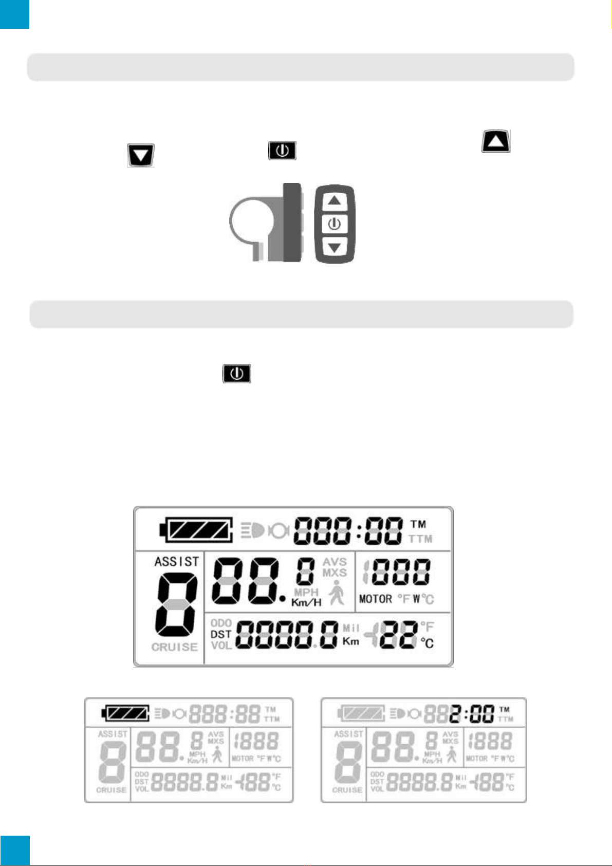
EBO KT-LCD3 User manual

KT-LCD3 User Manual

Contents
Preface...........................................................................................................................................
4
Outlook and Size...……………………………………………………………………………………….
4
Installation Instruction...………………………………………………………………………………...
6
Function Overview...…………………………………………………………………………………......
7
Display Content...………………………………………………………………………………………...
7
Button Definition...……………………………………………………………………………………….
8
Basic Operation...………………………………………………………………………………………...
8
On/Off...………………………………………………………………………………………...
8
Display Interface...………………………………………………………………….…………
8
Battery Capacity Indicator...………………………………………………………………...
12
Pedal Assist Level………......……….………..………….................................................
12
Power Walk Function...……………………………………………………………………...
13
Cruise Function...…………………………………………………………………………….
13
Backlight…………………...………………………………………………………………….
13
Motor Operating Power and Temperature.……………………………….……………….
14
Ambient Temperature.……………………………………………………….………………
14
Single Data Clearing.………………………………………………………….……….…….
14
Automatically Prompt Interface.………………………………………………….…………
15
User Setting..………..…………………………………………………………………………………...
16
General Setting.………………………………………………………………………………………….
16
Maximum Speed.……………………….……………………………………………………
16
Wheel Diameter.....…………………………………….…………………………………….
17
Units.………………………………………………………………………………….……….
17
P Parameter Setting..…………………………………………………………………………………...
18
P1 Motor Characteristic Parameter Setting.……………………………………….……...
18
P2 Wheel Speed Pulse Signal Setting.……………………………………………………
18
P3 Throttle Assist Level Control Setting.………………………………………………….
19
2

P4 Throttle Activation Setting.……………….……………………………………………..
19
P5 Battery Monitoring Setting.………………………………………………………...……
20
C Parameter Setting.…………………………………………………………………………………...
20
C1
Pedal Assist Sensor Setting.…………..……………………………………………….
21
C2
Motor Phase Classification Coding Mode.……………………………………………
22
C3
Pedal Assist Ratio Level Initialization.……………….…………………….………….
22
C4
Throttle Function Setting.………………………………….……………………………
23
C5
Controller Maximum Current Setting.……………………….…………………………
23
C6
Backlight Brightness Setting…….…………….……….…………………….…………
24
C7
Cruise Control Function Setting.……………….………………………………………
25
C8
Motor Operating Temperature Display Setting.………………………………………
25
C9
Startup Password Setting……………………………………………………………….
26
C10
Restore Default Setting………………………………………………………...……...
27
C11
LCD System Version Setting………………………………………………………….
27
C12
Controller Minimal Voltage Setting……………………………………………...……
28
C13
ABS Brakes and Anti-Charge Control Setting……………………………...……….
29
C14
Pedal Assist Tuning Setting……………………………….……………………….….
30
Parameter Copy………………………………………………………………………………………….
30
Version Information…………………………………………………………………………………….
31
Contact Us…….……………………………………………………………………………...………….
32
Default Settings………………………………………………………………………………...……….
33
3

PREFACE
This manual aims to help the user understand and familiarize themselves with the KT-LCD3
functions, operation, setting the e-bike Parameters, how to achieve the best match of the e-
bike components to improve performance of the electric bike system. The manual covers
installation, operation, parameter setting of the LCD and how to use it properly, which help
user setup the functionality of the electric bike system.
OUTLOOK AND SIZE
LCD Dimension (mm)
Dual Bracket Mounting Dimension (mm)
4
86
58
30
65
96
20
14
12

Button Control Box Dimensions (mm)
Main Material and Color
The KT-LCD3 and button control box are primarily constructed of polycarbonates (PC)
and are of a dark gray or black color.
Wiring Schematic
5
LCD
JULET Connectors
36V
Control
Ground
Data 1
Data 2
Red
Blue
Black
Green
Yellow
16.3
11
23
45
Ø 22.2
JULET KT-LCD3 Connector
Ground
36V
Data 2
Data 1
Control

INSTALLATION INSTRUCTION
Using the appropriate methods and fixtures, mount the LCD screen and button box onto
the handle bar to the rider’s desires. Refer to the following images below for installation on
specific handle bar diameters. While the e-bike is off, connect the necessary wiring and
check to make sure all connections are firmly attached. Finally, remove the protection film
from the display.
Ø 31.8 Handlebar Diameter Install
Ø 22.2 Handlebar Diameter Install
Installed KT-LCD3
6
LCD and Bracket Side View
LCD and Bracket View
LCD and Bracket Side View
Optional Encircled Rubber LCD
Bracket Mounts Ø22.2 or Ø25.4
Optional Encircled Rubber LCD
Bracket Mounts Ø22.2 or Ø25.4
Optional Encircled Rubber LCD
Bracket Mounts Ø22.2 or Ø25.4
LCD and Bracket View

FUNCTION OVERVIEW
KT-LCD3 provides a variety of functions such as electric bike controls and electric bike
status digitally displayed to meet the trip demands.
Trip time display (with displays of a single trip time (TM) and total trip time (TTM));
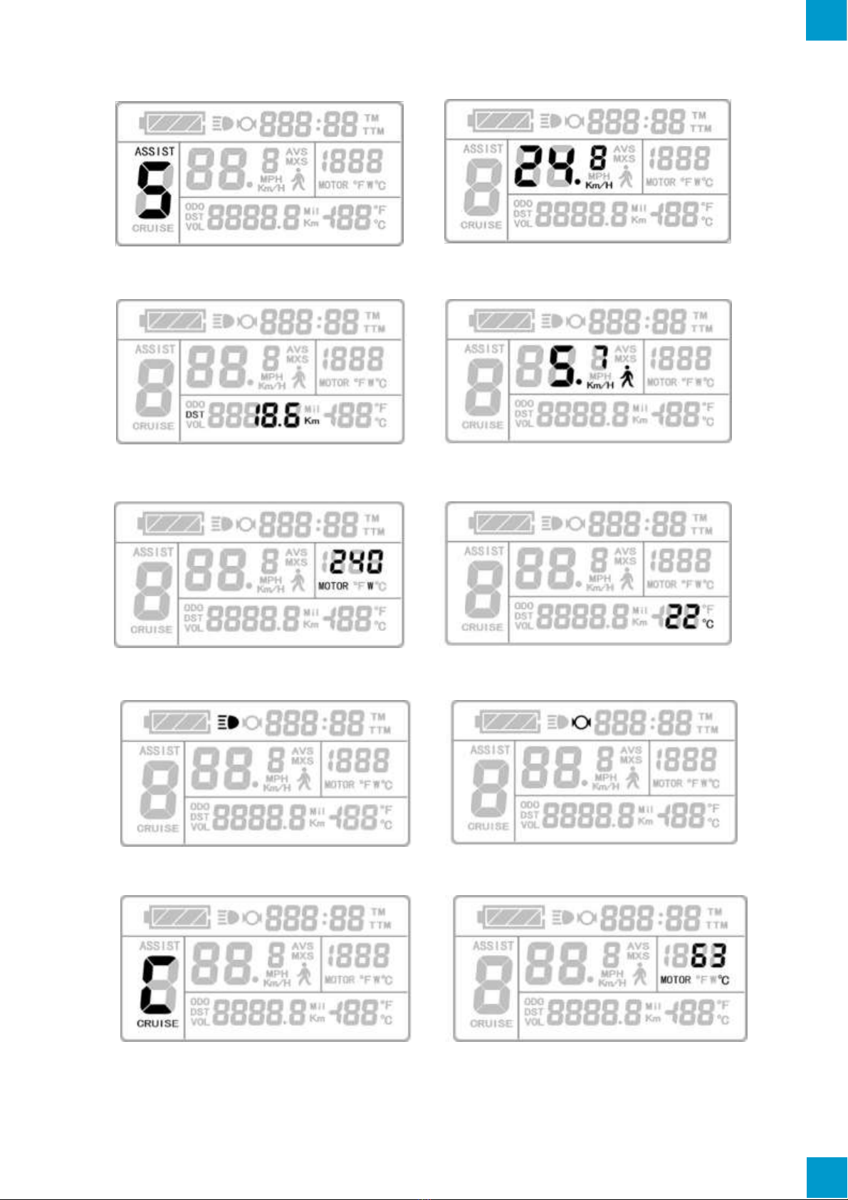
Trip speed display (with displays of real-time speed (Km/H or MPH) and a single
maximum speed (MXS) and a single average speed (AVS));
Trip distance display (with displays of a single trip distance (DST) and total trip distance
(ODO));
Functions of throttle;
Functions of pedal assist system;
Pedal Assist Level (ASSIST);
6Km/H power walk ( ) function;
Cruise function (CRUISE);
Battery capacity indicator ( );
Real-time battery voltage (VOL) display;
Motor power and temperature (MOTOR) display;
Brake display ( );
Turn on backlighting and lights ( );
Environment temperature (°C or °F) display;
Data clearing;
Fault code display;
User Parameter setting
24V, 36V, 48V supply voltage can automatic identification and be compatible
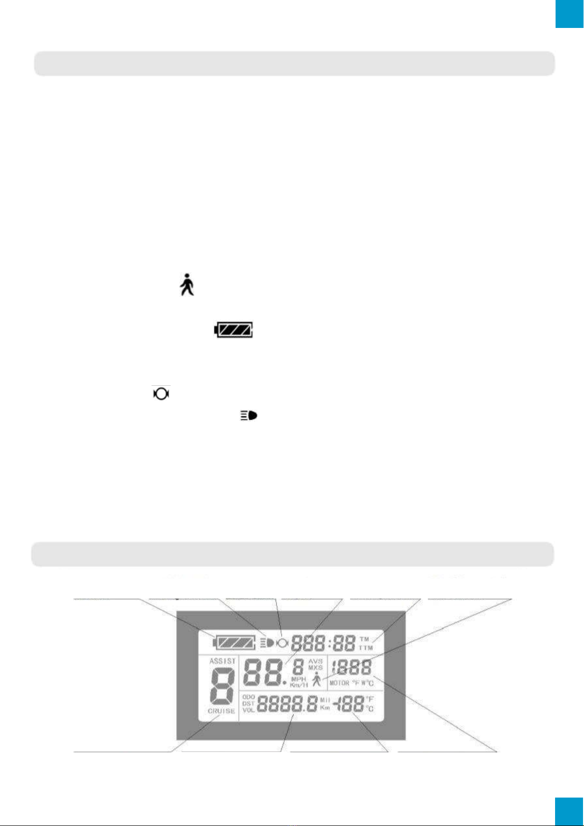
DISPLAY CONTENT
7
Pedal Assist Level and
Cruise Function
Battery Capacity
Indicator
Backlight Status
Brake Status
E-Bike Speed
Trip Time and
Total Trip Time
Power Walk Function
Trip Distance or Real-time
Battery Voltage
Environment Temperature
Motor Operation Power (Watts)
or Motor Run Temperature

BUTTON DEFINITION
KT-LCD3 is designed with the display in the center of the handlebars and electric bike
control buttons next to the left-hand grip of the handlebars for ease and safety.
There are three buttons on the operating panel of the box, which are icons of
button (UP), button (DOWN) and button (POWER).
Button Control Box and Operating Panel
BASIC OPERATION
On/Off
To turn on or off, hold down button for 2 seconds. System will automatically shut
down when stationary and not in use for five minutes. Note: System requires PAS or
throttle in use for a constant of 20 –25 seconds to activate. When powered off, the power
consumption of the LCD and controller is zero.
Display Interface
Display 1: The LCD is configured to enter this display on start-up.
The following are shown on display 1.
Battery Capacity Indicator Single Trip Time (TM)
8

Pedal Assist Levels Real-Time Trip Speed (Km/H)
Single Trip Distance (DST) 6Km/H Walk Function
Motor Operation Power Environment Temperature
Backlight Brake Status
Cruise Function (CRUISE) Motor Running Temperature
9

Display 2: To enter display 2, press the button while in display 1. The interface will
display as shown below.
Display 2
Total Trip Time (TTM) Total Trip Distance (ODO)
Single Average Speed (AVS) Motor Operating Temperature
Once the e-bike is in riding mode, after five seconds display 2 automatically reverts to
display 1. The original motor power is replaced by the motor running temperature as
shown below. To return to motor output, cycle through the displays back to display 1.
10

Display 3: To enter display 3, press the button while in display 2. The interface will
display as shown below.
Display 3
Single Maximum Speed (MXS) Real-Time Voltage (VOL)
Once the e-bike is in riding mode, after twenty seconds the single maximum speed will
return to real-time speed (Km/H) as shown below.
To return to display 1, press button.
Display of Powered Motor: When motor is powered, the LCD will display and animate the
following interface to indicate the motor is drawing power. This will only last a duration of 5
- 20 seconds before reverting to display 1. The interface will appear as follows.
11

Display of Powered Motor
Display of Power-Assist: When motor is operating under power-assistance, the display
interface flashes the “ASSIST” sign. The indicator will cease after 5 - 20 seconds.
Display of Power-Assist
Battery Capacity Indicator
The KT-LCD3 can identify 24V, 36V, 48V battery capacities when used with supporting
controllers. When the battery capacity is over 70%, four bars from the battery indicator will
be displayed. As the battery capacities drop, the bars will change accordingly. Once the
power capacity is less than 15%, the battery indicator will be empty and show zero bars. If
the power display frame flashes, it is due to voltage shortage where the controller will
power off.
Pedal Assist System (PAS)
Press button or button to adjust the pedal assist level (ratio), changing the
motor power output. Range of pedal assist is between 1 and 5 (this can also be configured
according to the rider’s requirements), where one provides the lowest power and five
provides the highest. When the PAS level is set to zero, the pedal assist function is off.
12

Power Walk Function
Users can use power walk function for assistances while walking alongside the e-bike or
riding in crowds. Hold button and the motor will provide power until e-bike reaches 6
Km/H. The LCD assists
function icon will flash indicating the function is active. By releasing the button,
the function will be deactivated.
Cruise Function
When the e-bike is traveling above 7Km/H, hold button for 3 seconds to set the
cruise function. The LCD will display "CRUISE" and "C" to indicate that the cruise function
has been activated (as seen in the figure below). Brake or hold any button to deactivate
cruise. Note: This feature only works if it has been activated through the Parameter
settings (check C7 in Parameter setting).
Backlight
To turn on or off LCD backlight and e-bike, hold button for 3 seconds.
When this function is activated, the display will show sign to indicate it is on.
13
Cruise Function
Backlight Status

Motor Operating Power and Temperature
While e-bike motor is in use, real time output power from the motor is displayed on the LCD.
The operating temperature of the motor can be displayed with supporting sensors installed in
the motor to output the temperature. When the motor operating temperature exceeds the
warning value, temperature display flashes to alarm the rider. In this circumstance, the motor
controller will offer the appropriate protection to motor and auto shutoff.
Ambient Temperature
Upon start-up the environment temperature is displayed on the bottom right hand
corner. The displayed figure may not accurately indicate the environment temperature
immediately after start up, however will adjust within 10 minutes.
Single Data Clearing
After five seconds after turning on LCD, while on display 1 hold both the button and the
button simultaneously for 3 seconds. The single trip time (TM) and single trip
distance (DST) will flicker. Press button and the record contents of both will be cleared. If
there are no operations within five seconds of (TM) and (DST) flashing, the
LCD will return to display 1, and the original record content will be saved.
14

Automatically Prompt Interface
Error Code Display: When there are issues with the electronic control system of the e-
bike, the LCD will automatically display (flicker) a fault code. This cannot be removed until
fault is fixed. Refer to Error Code & Definition Table for reference.
Motor operating temperature alarm: When the motor operating temperature exceeds the
warning value, the motor operating temperature display flashes to alarm the rider, while the
controller will provide the appropriate protection to the motor.
Error Code Display
Error Code & Definition Table:
Error Code
Definition
01_info
Throttle Abnormality
03_info
Motor Hall Signal Abnormality
04_info
Torque Sensor Signal Abnormality
05_info
Axis Speed Sensor Abnormality
06_info
Motor or Controller Short Circuited
15

USER SETTING
The KT-LCD3 LCD provides users with 3 depths of settings:
General Setting
P Parameter Setting
C Parameter Setting
To enter the general project setting, simultaneously hold button and button for
3 seconds within 5 seconds of turning the LCD on. The current setting will be
indicated by a flashing sign. To scroll through the menu, press the button.
Once the general project menu has been cycled through, the display will cease
flashing. Now enter the P Parameter settings by simultaneously holding button
and button for 3 seconds. The same method to scroll through the menu can be
applied and the LCD will flash specific icons indicating the setting currently open.
Once the flashing has stopped, hold down both the and button again to
progress to the C Parameter settings. To exit these settings at any stage, simply hold
down the button where the LCD will return to display 1. If no button operation occurs
for 60 seconds while in a settings menu, the KT-LCD3 will discard changes and
return to display 1. To exit at any moment, hold and the LCD will discard any
unsaved changes and revert to display 1.
GENERAL SETTING
Maximum Trip Speed
Turn on LCD, and within 5 seconds of start-up simultaneously hold button
and button for 3 seconds to enter general project settings. “MXS” and the speed
will be displayed, indicating the maximum riding speed (Refer to image below for
illustration). To adjust, press the button to increase or button to decrease
the speed. Once desired speed has been selected, press the button to confirm
changes and move onto wheel diameter.
16

Wheel Diameter
While in the general setting, cycle through the menu using the button
until the values of wheel diameter are flashing. Use the button and button to
scroll through the selection of the following wheel diameters: 6, 8, 10, 12, 14, 16, 18, 20,
22, 24, 26, 700C and 28 inches. Confirm selection by pressing the button.
Units
While in the general setting, cycle through the menu using the button until
the values of units are flashing (as shown below). Use the button and button
to scroll through the selection of units. Confirm selection by pressing the button.
Definition Table of Metric/Imperial Units:
Unit
Metric
Imperial
Speed
Km/H
MPH
Distance
Km
Mil
Temperature
°C
°F
17

PARAMETER SETTING
Enter the P Parameter settings by cycling through the General Project Settings to the
end (when display ceases flashing) and simultaneously holding button and
button for 3 seconds. If required to exit at any Parameter, hold button for 2
seconds. Use the button and button to select the value and confirm selection
by pressing the button. The Parameter will be saved and the LCD will enter the next P
Parameter settings.
P1 Motor Characteristic Parameter Setting
P1 Display
The P1 settings are a motor characteristic Parameter where:
P1 = Motor Gear Reduction Ratio × Number of Rotor Magnets
Rounding to a full number is necessary. The P1 setting ranges between 1 and 255.
P2 Wheel Speed Pulse Signal Setting
The P2 Parameter setting will display on the LCD after the P1 Parameter setting has been
selected and confirmed. The KT-LCD3 will display as follows:
P2 Display
18

The P2 Parameter is a setting mode for wheel speed pulse signal. If wheel generated 1
pulse signal by a revolution, the P2 value should be set to 1. If the wheel generated 6 pulse
signals by a revolution, P2 should be set as 6. If users did not configure the Parameter then
P2 can be set to 0. The selection of P2 values ranges from 0 to 6.
P3 Throttle Assist Level Control Setting
The P3 Parameter setting will display on the LCD after the P2 Parameter setting has been
selected and confirmed. The KT-LCD3 will display as follows:
P3 Display
P3 Parameters affect the pedal assist system (PAS) control setting. When the value is set
to 0, the throttle is dependent on the PAS level ratio. This means when the PAS level ratio
is 1, the throttle will provide the least amount of power, whereas when it is 5, the throttle will
provide the most power. If the P3 Parameter is set to 1, the throttle independent from assist
levels and will provide maximum power regardless of the PAS level chosen.
P4 Throttle Activation Setting
The P4 Parameter setting will display on the LCD after the P3 Parameter setting has been
selected and confirmed. The KT-LCD3 will display as follows:
P4 Display
19

The P4 settings is for controlling the throttle activation. When the P4 Parameter is 1, the
throttle is under "delayed startup” where the throttle will only activate the motor after the
motor has been activated via Pedal Assist System. Setting the P4 to 0 will set the throttle
to activate the motor when triggered.
P5 Power Monitoring Setting
The P5 Parameter setting will display on the LCD after the P4 Parameter setting has been
selected and confirmed. The KT-LCD3 will display as follows:
P5 Display
The P5 Parameter is power monitoring mode. When the value is set to 0, the power
monitoring is in "real-time voltage" mode where the method to determine the battery
capacity is based on real-time voltage. Once the P5 Parameter is set to a specified value,
the power monitoring is in "smart power" mode where the value set is determined by the
battery characteristics. Such that, 24V lithium batteries are typically set between 4-11, 36V
lithium batteries set between 5-15 and 48V lithium batteries set between 12-20. The P5
Parameter setting ranges from 0-40.
C PARAMETER SETTING
Enter the C Parameter settings by cycling through the P Parameter Settings to the end
(when display ceases flashing) and simultaneously holding button and button
for 3 seconds. If required to exit at any Parameter, hold button for 2 seconds. Use
the button and button to select the value and confirm selection by pressing
the button. The Parameter will be confirmed and the LCD will enter the following C
Parameter settings.
20
Table of contents
Other EBO Bicycle Accessories manuals