Ebyte E18-DTU Series User manual


Chengdu Ebyte Electronic Technology Co., Ltd. E18-DTU Series User Manual
Copyright © 2012–20 23 , Chengdu Ebyte Electronic Technology Co., Ltd.
1
Table of contents
Chapter 1 Product Introduction ......................................................................................................................................3
1.1 Product Introduction .........................................................................................................................................3
1.2 Function Features ............................................................................................................................................. 3
1.3 Product Features ...............................................................................................................................................3
1.4 Device Type Introduction .................................................................................................................................5
1.4.1 Coordinator ............................................................................................................................................5
1.4.2 Router .................................................................................................................................................... 5
1.4.3 Terminal .................................................................................................................................................5
1.5 Supported product series .................................................................................................................................. 5
1. 6 Application Scenario ....................................................................................................................................... 5
Chapter 2 Mechanical Dimensions ................................................................................................................................ 6
2.1 Interface description .........................................................................................................................................6
2.2 Product size ...................................................................................................................................................... 8
2.3 Specifications ................................................................................................................................................. 10
2.3.1 Working parameters ............................................................................................................................ 10
2.3.2 Electrical parameters ...........................................................................................................................10
2.3.3 Hardware parameters .......................................................................................................................... 10
Chapter 3 Interface Definition ......................................................................................................................................11
Chapter 4 Working Mode ............................................................................................................................................. 11
4.1 Transmission mode .........................................................................................................................................11
4.2 HEX command mode (configuration mode) ..................................................................................................12
4. 3 Mode switching ............................................................................................................................................. 12
4. 4 Related parameters in transmission mode .....................................................................................................12
5 Quick Start .................................................................................................................................................................13
5.1 Quickly build a ZigBee network .................................................................................................................... 13
5.2 Quickly join a ZigBee network ......................................................................................................................15
5.3 Data transmission ........................................................................................................................................... 17
5.4 Data transmission between network nodes ....................................................................................................20
Chapter 6 Sending and receiving methods ...................................................................................................................24
6.1 The way of sending data in transparent transmission mode .......................................................................... 24
6.1.1 broadcast mode ....................................................................................................................................24
6.1.2 Unicast mode .......................................................................................................................................24
6.1.3 Multicast mode ....................................................................................................................................25
6.2 The way of sending data in HEX command mode ........................................................................................ 25
Chapter 7 Application Function ................................................................................................................................... 25
7.1 Function ..........................................................................................................................................................25
7.1.1 Detailed explanation of LINK light .................................................................................................... 25
7.1.2 Detailed Explanation of RUN Light ................................................................................................... 25
7.1. 3 Detailed explanation of SMART key .................................................................................................26
7.1.4 Automatic Pairing and Mark Adaptation (Identify) Mode ................................................................. 26
7.1.4.1 Mark Adaptation (Identify) mode .................................................................................................... 26
7.1.4.2 Automatic pairing .............................................................................................................................26
7.2 Wireless remote configuration function .........................................................................................................27
Chengdu Ebyte Electronic Technology Co., Ltd. E18-DTU Series User Manual
Copyright © 2012–20 23 , Chengdu Ebyte Electronic Technology Co., Ltd.
2
Chapter 8 User Notice .................................................................................................................................................. 28
8.1 Network structure ...........................................................................................................................................28
Chapter 9 Practical Application Fields .........................................................................................................................29
Chapter 10 Precautions for Use ....................................................................................................................................30
Chapter 11 Important Statement ...................................................................................................................................30
Revise history ............................................................................................................................................................... 31

Chengdu Ebyte Electronic Technology Co., Ltd. E18-DTU Series User Manual
Copyright © 2012–20 23 , Chengdu Ebyte Electronic Technology Co., Ltd.
3
Chapter 1 Product Introduction
1.1 Product Introduction
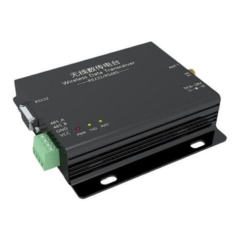
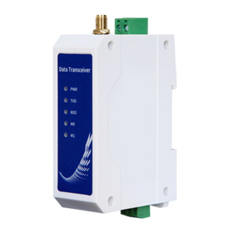
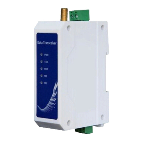
E18-DTU(Z20-485), E18-DTU(Z27-485) is a wireless data transceiver based on ZigBee3.0
technology, with transparent transmission, protocol transmission, and other functions. As a
communication medium, wireless data transceiver has a certain scope of application like optical fiber,
microwave, and wire; It provides real-time and reliable data transmission of monitoring signals in
private networks under certain special conditions, and has the advantages of low cost, easy installation
and maintenance, strong diffraction ability, flexible network structure, and long coverage. It is suitable
for occasions with many scattered points and complex geographical environments. It can also be
connected with data terminals such as PLC, RTU, rain gauge, and liquid level gauge.
1.2 Function Features
★All core components are imported with original packaging. Compared with the current similar imported digital radios, it has the
most advanced functions, the smallest volume and the best price.
★Multi-level transmitting power is available .
★Working temperature: -40℃~+85℃, suitable for various harsh working environments, it is a real industrial grade product.
★All aluminum alloy shell, compact size, easy installation, good heat dissipation; perfect shielding design, good electromagnetic
compatibility, and strong anti-interference ability.
★Power supply reverse connection protection, over-connection protection, antenna surge protection and other multiple protection
functions greatly increase the reliability of the radio.
★Powerful software function, all parameters can be set by programming: such as power, frequency, address ID, etc.
★Built-in watchdog, with precise time layout, once an abnormality occurs, the module will automatically restart, and can continue
to work according to the previous parameter settings.
1.3 Product Features
Centralized network management: ZIGBEE 3.0 security standard centralized network access mechanism, with data
security and reliability;
Interoperability: Comply with zigbee 3.0 standard network mechanism, compatible with ZCL network protocol;
Role switching: the user can switch the device arbitrarily among the three types of coordinator, router and terminal
through serial port commands ;
Support multiple network topologies: point-to-point, star network, MESH network;
Network self-healing: If the middle node of the network is lost, a new Mesh topology is automatically formed, and the
lost node is automatically retrieved after restarting;

Chengdu Ebyte Electronic Technology Co., Ltd. E18-DTU Series User Manual
Copyright © 2012–20 23 , Chengdu Ebyte Electronic Technology Co., Ltd.
4
Automatic resend: In the on-demand (unicast) mode, the device will automatically resend when it fails to send to the
next node, and the number of re-sends for each message is 2 times.
Automatic routing: the module supports the network routing function; the router and the coordinator carry the network
data routing function, and the user can carry out multi-hop networking .
Open and close network networking: The coordinator controls the opening or closing of the network. During the period
of time when the network is open, devices that comply with the ZigBee3.0 standard can join the network. After the
network is closed, no device can join. After the coordinator opens the network, if there is no operation to close it, it will
automatically close after 180 seconds.
One-click network addition: nodes do not need to set PANID and channel, but only need to trigger network addition
within the window time when the coordinator opens the network.
Automatic channel and PANID: The coordinator automatically creates a network on the optimal channel, and
automatically assigns a PANID to avoid duplication with other coordinators.
Automatically obtain the MAC address: the coordinator can obtain the MAC address and short address of the node when
the node is connected to the network, without further processing on the device side.
Multi-type data communication: support network-wide broadcast, multicast and on-demand (unicast) functions; also
support several transmission modes in broadcast and on-demand (unicast) modes.
Address search: users can find the corresponding short address according to the MAC address (unique, fixed) of the node
that has joined the network, and can also find the corresponding long address of each node in the network according to
the short address of the node;
Data security: Integrating ZIGBEE 3.0 security communication standard, the network contains multi-level security keys;
Channel change: support 16 channels such as 11~26 (2405~2480MHZ), different channels correspond to different
frequency bands.
Network PAN_ID change: Any switching of network PAN_ID, user can customize PAN_ID to join the corresponding
network or automatically select PAN_ID to join the network.
Serial port configuration: The module has built-in serial port commands, and users can configure (view) the parameters
and functions of the module through serial port commands;
One-key recovery of baud rate: When the current baud rate of the radio is forgotten, the baud rate of the radio can be
restored to 115200bps through the SMART key.
Serial port baud rate change: users can set the baud rate by themselves, up to 115200 bps , the default number of bits is 8
bits, stop bit is 1 bit, and there is no parity bit.
Module reset: The user can reset the module through the serial port command.
restore the factory settings of the module through serial port commands or the "SMART" key.
Over-the-Air Configuration: Users can remotely configure other devices in the network using air configuration
commands.
Multiple command formats: users can use hexadecimal format commands and AT commands to configure and control the
module, realize networking, set transparent transmission, control lights and other operations.
Possess a national invention patent certificate, invention name: a ZigBee3.0-based wireless transparent transmission
module interconnection method, patent number: ZL 2019 1 1122430.X

Chengdu Ebyte Electronic Technology Co., Ltd. E18-DTU Series User Manual
Copyright © 2012–20 23 , Chengdu Ebyte Electronic Technology Co., Ltd.
5
1.4 Device Type Introduction
There are three logical device types in the ZigBee network: Coordinator (coordinator), Router (router), and End-Device (terminal).
ZigBee network consists of a Coordinator, multiple Routers and multiple Terminals.
1.4.1 Coordinator
It has the function of establishing and managing the network, controls whether other nodes are allowed to join the network, stores
network information, and has all the functions of routing equipment. Its main task is to manage the network, record child node
information, and forward messages. At the same time, the coordinator needs to identify the authority of the terminal requesting
network access. After the coordinator is powered off, the network will not crash , and routers and terminals will work normally in the
current network.
1.4.2 Router
It allows other nodes to connect with routing devices to expand the coverage of the network. Its main task is to forward messages,
play the role of relay routing, and have all the functions of terminal devices. If there are multiple paths from one node to another node,
when one of the paths fails, the network will automatically adjust to other optimal paths for transmission to ensure data arrival. A
router can set up its own network, or join someone else's, and the router is always active, so it must be powered by mains power.
1.4.3 Terminal
The main task of the terminal device is to send and receive messages, and other terminal nodes are not allowed to connect to the
terminal device. The terminal is always in working condition and can receive and send data at any time.
1.5 Supported product series
Product number
RF chip
Frequency (Hz)
Airspeed (bps)
Power (dBm)
Antenna interface
E18-DTU(Z20-485)
CC2530
2.4G
250K
20
SMA-K
E18-DTU(Z27-485 )
CC2530
2.4G
250K
27
SMA-K
★E18 series wireless modules can communicate with the above radios★
1. 6 Application Scenario
Smart home and industrial sensors, etc.;
Security system;
Wireless remote control for games;
Healthcare products;

Chengdu Ebyte Electronic Technology Co., Ltd. E18-DTU Series User Manual
Copyright © 2012–20 23 , Chengdu Ebyte Electronic Technology Co., Ltd.
6
Advanced Meter Reading Infrastructure (AMI);
Automotive industry applications;
Building automation solutions;
Agricultural greenhouse automation application.
Chapter 2 Mechanical Dimensions
2.1 Interface description
Interface Description:
serial
number
name
Function
illustrate
1
VCC
Crimp type power interface,
positive pole
DC 8~28V, 12V or 24V is recommended
2
GND
Crimp type power interface,
negative pole
The negative pole of the power supply is connected to the
system ground and the shell
3
AGND
common ground interface
It can be connected to the ground terminal of external

Chengdu Ebyte Electronic Technology Co., Ltd. E18-DTU Series User Manual
Copyright © 2012–20 23 , Chengdu Ebyte Electronic Technology Co., Ltd.
7
equipment, or it can not be processed
4
RS485-B
serial terminal
Connect to the B terminal of other RS485 devices;
5
RS485-A
serial terminal
Connect to the A terminal of other RS485 devices;
12
Antenna interface
SMA-K interface
External thread and inner hole, length 8 mm,
characteristic impedance 50Ω
Indicator light description:
serial
number
name
Function
Instructions
6
PWR-LED
Power Indicator
Red, always on when the power is on
7
TXD-LED
Send Light
Yellow, blinking when sending data
8
RXD-LED
Receive indicator
Yellow, blinking when receiving data
Button function description:
serial
number
name
Radio status
LED status
Remark
9
LINK-LED
Not networked
turn off
Network provisioning - the
coordinator or router opens the
network
1Hz flickering
Network provisioning - a router
or terminal that is not
connected to the network joins
the network
10Hz flashing
The router or terminal network
joins successfully
2Hz flashes for 3 seconds
and then stays on
The network connection is
normal
always on
Network establishment/join
failure
turn off
Terminal goes offline
5Hz flashing, 3 times per
second
serial
number
name
Function
LED status
Remark
10
RUN-LED
automatic pairing mode
1Hz flickering
reset
always on
"SMART" button long press
5S
Serial port baud rate recovery
Off → On → Off
For details, see the
description of SMART
function keys
Standby/normal work
turn off

Chengdu Ebyte Electronic Technology Co., Ltd. E18-DTU Series User Manual
Copyright © 2012–20 23 , Chengdu Ebyte Electronic Technology Co., Ltd.
8
2.2 Product size
serial
number
name
station status
Function
button action
LED status
11
SMART
The coordinator did not
create the network
The coordinator creates the
network
short press
LINK light flashes at 10Hz
The coordinator has
created the network
Coordinator Open Network
short press
LINK light flashes at 1Hz
The router/terminal is not
configured with a
network
Start to configure the
network
short press
LINK light flashes at 10Hz
The router/terminal has
been configured with a
network
enter auto pairing mode
short press
RUN light flashes at 1Hz
The router/terminal has
been configured with a
network
Clear the network (exit the
current network)
Long press for 5
seconds
The RUN light is always on
The router/terminal is not
configured with a
network
Restore Factory
Long press for 5
seconds
The RUN light is always on
any state
Serial port baud rate
recovery (115200bps)
Press button “SMART”
while the radio is
powered on , wait for 5
seconds, and release the
SMART button after the
RUN light is on.
RUN light: off→on→off
serial number
name
describe

Chengdu Ebyte Electronic Technology Co., Ltd. E18-DTU Series User Manual
Copyright © 2012–20 23 , Chengdu Ebyte Electronic Technology Co., Ltd.
9
1
size
68*66*21mm
2
weight
64g±5g

Chengdu Ebyte Electronic Technology Co., Ltd. E18-DTU Series User Manual
Copyright © 2012–20 23 , Chengdu Ebyte Electronic Technology Co., Ltd.
10
2.3 Specifications
2.3.1 Working parameters
2.3.2 Electrical parameters
Electrical
parameters
unit
model
Remark
E18-DTU(Z20-485)
E18-DTU(Z27-485)
Operating
Voltage
V
+8 ~ +28V DC
12V or 24V power supply is
recommended
emission
current
mA
78 @20dBm
281.3 @27dBm
Operating
temperature
℃
-40 ~ +85
industrial grade
storage
temperature
℃
-40 ~ +125
2.3.3 Hardware parameters
The main
parameters
parameter value
Remark
main
parameters
unit
model
Remark
E18-DTU(Z20-485)
E18-DTU(Z2 7-485 )
Working
frequency
GHz
2.405 ~ 2.480
Support ISM frequency band
transmit power
dBm
20
27
blocking power
dBm
0 ~ 10.0
Less chance of burning when used at
close range
Receiver
sensitivity
dBm
-98.0±1.0
-99.0±1.0
The air rate is 250kbps
Serial baud
rate
bps
9600, 19200, 38400, 57600, 115200
Default 115200bps
Matching
impedance
Ω
50
Equivalent impedance
Minimum
sending packet
length
byte
1
Measured
distance
Km
1.2
2.5
It is clear and open air, the antenna
gain is 5dBi , the height is 2.5 meters,
and the air rate is 250kBps .

Chengdu Ebyte Electronic Technology Co., Ltd. E18-DTU Series User Manual
Copyright © 2012–20 23 , Chengdu Ebyte Electronic Technology Co., Ltd.
11
RF chip
CC2530
original imported TI chip
Product
Size
68*66*21mm
Antenna not included
FLASH
256KB
RAM
8KB
supporting
agreement
ZigBee 3.0
Communica
tion
Interface
RS485
3.81mm terminal block
Antenna
interface
SMA-K
External thread inner hole
Chapter 3 Interface Definition
Users need to use the VCC terminal and GND terminal in ①to supply power. E180-DTU can use 8~28V DC power supply, and
12V or 24V DC power supply is recommended.
★Note: When the radio is connected to multiple devices, the communication is not smooth, but there is no such phenomenon with a
single device, please try to connect a 120Ω resistor in parallel between the 485_A terminal and the 485_B terminal.
Chapter 4 Working Mode
4.1 Transmission mode
When the module enters the transmission mode, any data received by the serial port will be sent out wirelessly. The transmission
mode is wireless communication between network nodes. The communication methods include unicast, broadcast, multicast, etc.
There are 4 transmission modes:
The first is normal transmission. In this mode, "OK" will be returned if the transmission is successful, and errors such as "ERRO"
or "FAIL" or "BUSY" will be returned if the transmission is lost or data error occurs. There is a system logo output when the module
is disconnected or abnormal;
The second is no response transmission, in which there is no message returned when the transmission is successful, but when
there is failure or error in the transmission, or the module is offline, an error reminder will be printed;
The third is no Printing mode, the module will send any data received by the serial port to the designated target when the
connection is normal, and the module will not return any message when the transmission fails or the module is abnormal;

Chengdu Ebyte Electronic Technology Co., Ltd. E18-DTU Series User Manual
Copyright © 2012–20 23 , Chengdu Ebyte Electronic Technology Co., Ltd.
12
The fourth is the Modbus host mode, in which the first byte of the data frame received by the module serial port is ModbusID,
and there will be no normal or abnormal print messages during transmission. In this mode, the ModbusID of the slave needs to be set,
and the slave needs to be bound to the master. This mode is recommended used on coordinator or router only.
4.2 HEX command mode (configuration mode)
When the module enters the HEX command mode, the data received by the serial port defaults to the HEX command. If the serial
port data sent does not conform to the HEX command format, it will be automatically filtered out by the device as a HEX command in
the wrong format. In the HEX command mode, the data received by the module serial port is considered as HEX command. For details
of the specific HEX command, you can download the "Ebyte ZigBee 3.0 Module HEX Command Standard Specification" from the
official website.
4. 3 Mode switching
The power-on initialization of the module defaults to the HEX command mode.
Switch from HEX command mode (configuration mode) to transmission mode:
When the module serial port receives the HEX format command “ 55 07 00 11 00 03 00 01 13 ”, the module enters the normal
transmission mode, and returns the HEX format command “ 55 04 00 11 00 11 ” after entering the transmission mode successfully. If
you need to enter the no-response transmission mode, enter the HEX format command “ 55 07 00 11 00 03 00 02 10 ”; For no printing
mode, enter the HEX format command “ 55 07 00 11 00 03 00 03 11 ” . For the Modbus host mode, enter the HEX format command "
55 07 00 11 00 03 00 04 16 ".
Switch the transmission mode to HEX command mode (configuration mode):
In the transmission mode, when the serial port of the module receives the " +++ " character, it enters the configuration mode, and
returns he system notification command "device start" after successfully entering the configuration mode.
4. 4 Related parameters in transmission mode
The below parameters can be read and set through the HEX commands "read local attribute" and "set local attribute". The below
parameters of the module can be read and modified remotely through the HEX command "ZCL command - read device attribute" and
"ZCL command - modify device attribute". Note that remote modification is limited to items with "W" in "Operation".
AttrID
Descriptor
name
type of
data
operation
initial value
0x0000
Baud
baud rate
uint32
R
115200 (decimal)
0x0001
Target Addr
Transparent
transmission target
short address
uint16
RW
0xFFFF
0x0002
Target EP
Transparent
transmission target
port
uint8
RW
0xFF or 255

Chengdu Ebyte Electronic Technology Co., Ltd. E18-DTU Series User Manual
Copyright © 2012–20 23 , Chengdu Ebyte Electronic Technology Co., Ltd.
13
Baud: Modify this parameter to set or query the current baud rate of the module.
targetAddr: The target address in the transmission mode, 0xFFFF is broadcast transmission, and 0xFFFE is sent to the binding
target MAC.
targetEP: The target port in the transmission mode, set the value to 0xFF for broadcast sending or binding sending, set it to 0x01
for sending to the specified target short address, and set it to 0x00 for multicast sending.
send Mode: transmission mode setting, 0 - HEX command mode, 1 - normal transmission mode, 2 - no response mode, 3 - no
printing mode, 4 - Modbus host mode.
target IEEE: bind the target MAC, this item is only for viewing. The module can bind multiple target MACs, and the heartbeat
packet will be sent to all bound MACs in turn, but in the transmission mode, only the data is sent to the last binding target in the
binding table.
Modbus ID: The module will send this parameter to the coordinator and the bound target MAC in the form of a heartbeat packet
(once every 300 seconds). If the target device is a Modbus master, the Modbus master can find the zigbee network address of the slave
according to the Modbus ID of the slave.
User-defined variables: There are one 32bit, one 16bit, and two 8bit, total 4 user-defined variables. These values can be set and
queried through "Read Local Attributes" and "Set Local Attributes", remote setting and query are also supported to facilitate the status
management of the module.
5 Quick Start
In order to allow users to quickly familiarize themselves with the radio, this section will guide users to build a ZigBee network
through simple configuration with the host computer, including node type configuration, PANID setting, channel setting, and transmit
power setting.
5.1 Quickly build a ZigBee network
Combined with the host computer software to quickly and easily establish a ZigBee network, the specific steps are as follows:
(1) Connect the radio to the computer, open the host computer software "Ebyte ZigBee3.0 Setting", select the device type, select the
0x0003
Send Mode
Transparent mode
bool
RWP
0
0x0004
LP Level
low power mode
enum8
RP
0
0x0006
Modbus ID
Modbus number
uint8
RWP
0xFF
0x0010
User Attr 0
user-defined variable
0
uint32
RW
0x00000000
0x0011
User Attr 1
User-defined variable
1
uint16
RW
0x0000
0x0012
User Attr 2
User-defined variable
2
uint8
RW
0x00
0x0013
User Attr 3
User-defined variable
3
uint8
RW
0x00

Chengdu Ebyte Electronic Technology Co., Ltd. E18-DTU Series User Manual
Copyright © 2012–20 23 , Chengdu Ebyte Electronic Technology Co., Ltd.
14
serial port number, select the serial port baud rate (default 115200), and click to “Open Uart”.
(2) The module leaves the factory in HEX command configuration mode, click "Read Param", the message box prompts "Read
succeed", the main network parameters include: long address, the default radio type is coordinator (if not, please set it to Coordinator),
the network status is "not have" (if it is not, pls exit the network or restore the factory) . If failing to read parameters, it is possible that
the module is currently in transmission mode, and you need to click "Setting mode", and a message box will prompt "Enter
Configuration Status Successfully".
(3)Click "Start Net" to coordinate and establish an open network. After the coordinator creates a new network, it will continue to

Chengdu Ebyte Electronic Technology Co., Ltd. E18-DTU Series User Manual
Copyright © 2012–20 23 , Chengdu Ebyte Electronic Technology Co., Ltd.
15
open the network for 180 seconds. The LINK light flashes at 1Hz. Routers and terminals can join the network within this time.
5.2 Quickly join a ZigBee network
(1) Open the host computer software "Ebyte ZigBee3.0 Setting", select the device type, select the serial port number, select the serial
port baud rate (default 115200), click to "Open Uart". Then set the module type to "Router" or "Node", then click "Write Param", and
then click "RST", at this time the role of the device is switched successfully.
(2) Click "Start Net", and the LINK light of the DTU device flashes rapidly at 10Hz. At this time, it is necessary to ensure that the

Chengdu Ebyte Electronic Technology Co., Ltd. E18-DTU Series User Manual
Copyright © 2012–20 23 , Chengdu Ebyte Electronic Technology Co., Ltd.
16
coordinator device is also in the “Start Net” state (see section 5.1). Wait for a while, the LINK light of the DTU becomes solid or
flashes at 1Hz (router mode), click "Read Param", you can view the network access information of the device, and the “Net state” is
"connect". If the LINK light turns off and the network status is "not have", the module fails to add the network, please check whether
the coordinator device is in the “Start Net” state , and whether the distance between the coordinator device and the router/node is
within a reasonable range .
(3) Through the host computer interface of the coordinator device, you can view the information of other routers/nodes that have
joined the coordinator device network, including MAC addresses and short addresses. Click the "device join list" on the host computer
interface of the coordinator device to view the 9-byte SN number of the network-connected device (Note: a module may have multiple
SN numbers, and each SN number represents a peripheral or function. The more functions module has, the more SN numbers are
displayed), and the SN number can be used for device control and device binding transparent transmission targets.

Chengdu Ebyte Electronic Technology Co., Ltd. E18-DTU Series User Manual
Copyright © 2012–20 23 , Chengdu Ebyte Electronic Technology Co., Ltd.
17
(4) On the host computer interface of the coordinator device, click "Device Cmd", click "Refresh", and you can see the MAC address
and short address of the network-connected device.
According to this method, several routers and end nodes can be added to a coordinator network.
Precautions:
For routers or terminal nodes that have joined the network, if they need to switch to the network established by other coordinators,
they need to operate "Exit Net" or "Restore", and then follow the process of 5.2 to set up again. Similarly, if a router that has joined the
network needs to be changed to an end node, or an end node that has joined the network needs to be changed to a router, the operation
of "Exit Net" or "Restore" is also required.
5.3 Data transmission
(1) Open the host computer software of the coordinator device and the network-connected device, click "Read
Param", and confirm that the current "Net State" of the device is "connect", indicating that the device has been

Chengdu Ebyte Electronic Technology Co., Ltd. E18-DTU Series User Manual
Copyright © 2012–20 23 , Chengdu Ebyte Electronic Technology Co., Ltd.
18
networked.
Coordinator device Router device
(2) Click "read" to query the serial port configuration parameters of the device. The default serial port baud rate of
the device is 115200, the short address of the transparent transmission target is 0xFFFF, and the target port is 0xFF
(ie 255), that is, the device defaults to broadcasting in the transparent transmission mode.
(3) Then set the router device to transparently transmit data to the coordinator device in the form of on-demand,
and the coordinator device uses broadcast mode to transparently transmit data. In the host computer interface of the
router device, set the target short address to 00 00 (that is, 0x0000), set the target port to 01 (that is, 0x01 or 1), and

Chengdu Ebyte Electronic Technology Co., Ltd. E18-DTU Series User Manual
Copyright © 2012–20 23 , Chengdu Ebyte Electronic Technology Co., Ltd.
19
then click "set". After setting, you can click "read" again to confirm whether the setting is successful.
(4) Enter the transparent transmission mode. After clicking "Trans mode" on the host computer interface of the
coordinator device and the router device, both can enter the transparent transmission mode. One serial port inputs
any data, and the other serial port can completely output the same data.
Coordinator device Router device
After entering the transparent transmission mode, close the host computer configuration software and open the
serial port assistant. Input any data on either side, the other side will output the same data. The party that sends data
will return "OK" after sending data each time , indicating that the sending is successful, while return "FAIL" or
"ERRO" is to indicate failing to send.
This manual suits for next models
4
Table of contents
Other Ebyte Modem manuals

Ebyte
Ebyte E800-DTU User manual

Ebyte
Ebyte E95-DTU User manual

Ebyte
Ebyte EBT3002 T6 User manual

Ebyte
Ebyte E62-DTU (433D30) User manual

Ebyte
Ebyte E810 Series User manual

Ebyte
Ebyte NB183 User manual

Ebyte
Ebyte E32-DTU User manual

Ebyte
Ebyte E800-DTU V8 Series User manual

Ebyte
Ebyte E870-W1 User manual

Ebyte
Ebyte E78-DTU(470LN22) User manual

Ebyte
Ebyte E95-DTU User manual

Ebyte
Ebyte E90-DTU User manual

Ebyte
Ebyte E820-AIO User manual

Ebyte
Ebyte E880-IR01 User manual

Ebyte
Ebyte E840-TTL-4G02E User manual

Ebyte
Ebyte E890-915LG12 User manual

Ebyte
Ebyte E90-DTU User manual

Ebyte
Ebyte E92-DTU User manual

Ebyte
Ebyte E831-RTU Series User manual

Ebyte
Ebyte M31 Series User manual