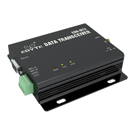
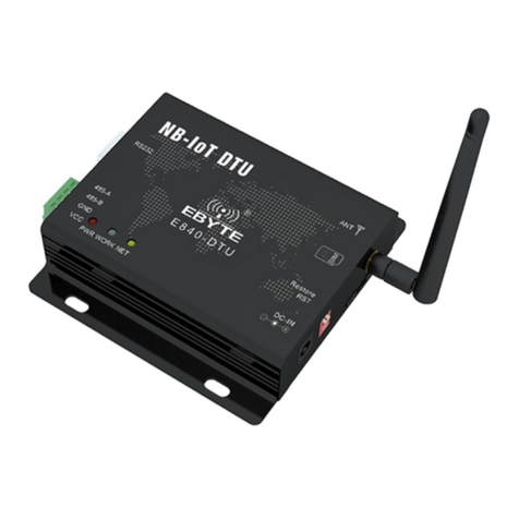
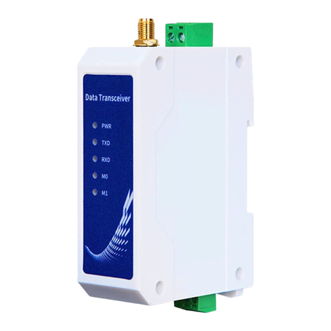
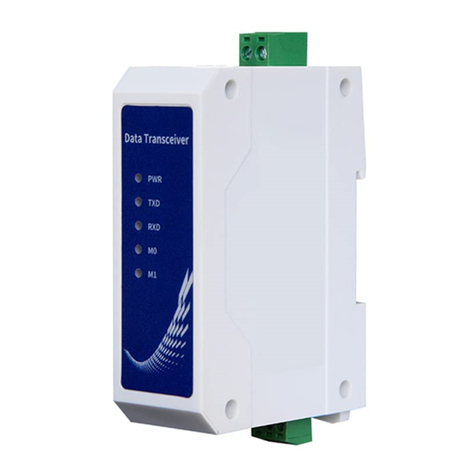
Ebyte E90-DTU User manual

SX1280 2.4GHz SPI 贴片
E90-DTU(2G4HD12)

Chengdu Ebyte Electronic Technology Co.,Ltd. E90-DTU(2G4HD12) User Manual
Copyright ©2012–2020,Chengdu Ebyte Electronic Technology Co.,Ltd.
1
Contents
1. Overview.....................................................................................................................................................................3
1.1 Introduction.......................................................................................................................................................3
1.2 Certificates (consistent with E90-DTU series).................................................................................................3
1.3 Features.............................................................................................................................................................4
2. Quick Start.................................................................................................................................................................. 5
2.1 Configuration Software Guide..........................................................................................................................5
2.2 Setting Steps..................................................................................................................................................... 6
3. Housing and Ports.......................................................................................................................................................9
4. Definitions.................................................................................................................................................................11
4.1 Power Connection Ports................................................................................................................................. 11
4.2 RS232 Interface.............................................................................................................................................. 11
4.3 RS485Interface............................................................................................................................................... 11
5. Parameters.................................................................................................................................................................12
5.1 Model details...................................................................................................................................................12
5.2 Other parameters.............................................................................................................................................12
5.3 Frequency range and Channels.......................................................................................................................12
5.4 Electronic Parameters..................................................................................................................................... 13
6. Working Mode.......................................................................................................................................................... 14
6.1 Modes..............................................................................................................................................................14
6.1.1 Transparent transceiving mode............................................................................................................14
6.1.2 Configuration Mode............................................................................................................................ 14
6.1.3 Mode Switching...................................................................................................................................14
6.1.4 DTU Reset........................................................................................................................................... 14
6.2 DATA LED Indicator...................................................................................................................................14
6.3 Point-to-point communication mechanism.................................................................................................... 15
6.4 Hardware baud rate control............................................................................................................................ 15
6.5 Full duplex/high-speed continuous transmission........................................................................................... 15
7. AT command............................................................................................................................................................. 16
7.1 Default Parameter for AT command...............................................................................................................16
7.2 AT Command Description.............................................................................................................................. 16
7.3 AT Command Error Code............................................................................................................................... 16
7.4 AT Command List...........................................................................................................................................16
7.4.1 AT Test................................................................................................................................................. 16
7.4.2 AT+RESET: Restart.............................................................................................................................17
7.4.3 AT+RESTORE: Restore to Default Setting........................................................................................ 17
7.4.4 AT+BAUD: Setting baud rate..............................................................................................................17
7.4.5 AT+PARITY, Parity Setting.................................................................................................................18
7.4.6 AT+HWFC , Serial flow control..........................................................................................................18
7.4.7 AT+LINK , Communication link setting.............................................................................................18
8. Devices Connection Reference.................................................................................................................................19
9.0 Similar products......................................................................................................................................................20
10. Appications:............................................................................................................................................................ 21


Chengdu Ebyte Electronic Technology Co.,Ltd. E90-DTU(2G4HD12) User Manual
Copyright ©2012–2020,Chengdu Ebyte Electronic Technology Co.,Ltd.
2
11. User Notes and Safety Notice.................................................................................................................................22
12. Copyrights Notice...................................................................................................................................................23
Revision History........................................................................................................................................................... 23
About us........................................................................................................................................................................ 23

Chengdu Ebyte Electronic Technology Co.,Ltd. E90-DTU(2G4HD12) User Manual
Copyright ©2012–2020,Chengdu Ebyte Electronic Technology Co.,Ltd.
3
1. Overview
1.1 Introduction
E90-DTU (2G4HD12) is a high-quality industrial-grade wireless data transmission radio station. Its high-level port
protection capability can be used in industrial situations with complex electromagnetic environments. Compared with
ordinary digital transmission radio: this radio has the characteristics of low delay, full duplex, automatic frequency
hopping, high-speed continuous transmission, etc., combined with its strong anti-interference ability, makes wireless
communication more stable and reliable in the industrial field.
E90-DTU (2G4HD12) is a point-to-point, frequency hopping, continuous transmission, duplex wireless data
transmission radio station, working in the free 2.4G frequency band around the world. The radio transmission power is
+12dBm, supports transparent transmission, provides RS232/RS485 interface, and supports 8~28 V voltage input.
Wireless transceiver has CRC check, FEC forward error correction, packet loss retransmission and other technologies,
plus automatic frequency hopping technology, so even in the case of sudden interference, it is almost unaffected, greatly
improving the reliability of wireless transmission And transmission distance. The radio has a two-way continuous
transmission function, so you don't need to pay too much attention to the length of the sub-packet, and you can send data
through the interface at any time without caring about the status of the receiving station.
As a communication medium, wireless data transmission station has a certain scope of application like optical fiber,
microwave and open wire: it provides real-time and reliable data transmission of monitoring signals in private networks
under certain special conditions, with low cost, installation and maintenance Convenience, strong diffraction ability,
flexible network structure, and long coverage, suitable for many and scattered locations, complex geographical
environment and other occasions. It can be connected with PLC, RTU, rain gauge, level gauge and other data terminals.
1.2 Certificates (consistent with E90-DTU series)
E90-DTU has obtained the "Radio Transmission Equipment Type Approval Certificate", code: CMIIT ID:
2017FP5780.
E90-DTU has obtained the "Explosion-proof Certificate", and its number is: Test No. 201711000975.
E90-DTU has obtained the "Static Surge Test Report" issued by the China Testing Institute, and its number is:
CNEx18.1461.
E90-DTU has obtained the "Appearance Design Patent Certificate", and its patent number is: ZL 2016 3 0501980.3.
E90-DTU has obtained the "utility model patent certificate", and its patent number is: ZL 2016 2 1410691.3.
E90-DTU has obtained the "CE certificate" (EU mandatory certification), and its verification number is:
CCISE180514601V.
E90-DTU has obtained "FCC certificate" (Federal Communications Commission certification), and its ID is:
2ALPH-E90-DTU.
E90-DTU has obtained the "RoHS Certificate" (EU Environmental Compulsory Certification), and its report
number is: DTI201807025245.

Chengdu Ebyte Electronic Technology Co.,Ltd. E90-DTU(2G4HD12) User Manual
Copyright ©2012–2020,Chengdu Ebyte Electronic Technology Co.,Ltd.
4
1.3 Features
Using automatic frequency hopping technology, it has strong anti-interference ability and stable communication;
Support two-way continuous data transmission function;
The product supports AT commands and host computer configuration;
4-level port protection capability;
Simple high-efficiency power supply design, support power supply configuration or pressure line mode, support 8 ~
28V power supply;
The transmit power can reach up to 12dbm, and all technical indicators meet European industrial standards;
Working temperature range: -40℃~+85℃, suitable for various harsh working environments, real industrial grade
products;
All aluminum alloy shell, compact size, easy installation, good heat dissipation; perfect shielding design, good
electromagnetic compatibility, strong anti-interference ability;
Multiple protection functions such as power reverse connection protection, over-connection protection, and antenna
surge protection greatly increase the reliability of the radio;
Simple and easy to use, wireless communication can be carried out after the factory power-on connection is
successful;
Built-in hardware watchdog, and accurate time layout, once an exception occurs, the module will automatically
restart, and can continue to work according to the previous parameter settings.

Chengdu Ebyte Electronic Technology Co.,Ltd. E90-DTU(2G4HD12) User Manual
Copyright ©2012–2020,Chengdu Ebyte Electronic Technology Co.,Ltd.
5
2. Quick Start
User needs to prepare below parts:
2.1 Configuration Software Guide
First install the antenna to the DTU, and then use USB to RS-232 or USB to RS-485 to connect the computer to the
DTU, M1 pulled up, M0 in any position to enter the configuration mode.
The software is used to query and set the module parameters, and the radio station needs to work in configuration mode.
The software interface is shown in the figure below:
Picture 2-1 PC software interface
Software Description
No
Description
1
Serial port parameter area
2
Command execution area
3
Parameter area
4
Special command area

Chengdu Ebyte Electronic Technology Co.,Ltd. E90-DTU(2G4HD12) User Manual
Copyright ©2012–2020,Chengdu Ebyte Electronic Technology Co.,Ltd.
6
1: Select the current baud rate and parity bit of the module, select the corresponding port number, and open the serial port.
You must make the module work in configuration mode and select the correct serial port parameters, otherwise the
operation instructions will fail.
2: Read parameters and write parameters Click to read parameters, it prompts that the read parameters are successful, and
the current parameters of the module are displayed in the parameter area. Click to write parameters, and it prompts that
the write parameters are successful. The parameters selected/filled in the parameter area have been written into the
module
3: The parameter area is used with the "Read Parameters" button to display the current module parameters, or to modify
the parameters with the "Write Parameters" button to set the module parameters.
4: Restart and restore factory settings special instructions, which are used to reset the module and restore the module
parameters to the factory state.
2.2 Setting Steps
1.First, install the antenna to the DTU, and then install the power supply, M1 pulled down, M0 in any position and enters
the transparent transmission mode. The user can power the DTU either by RS485 or power adaptor.
2.Use USB to RS-232 or USB to RS-485 to connect the computer to the DTU. Then connect the DTU power supply. The
DTU will automatically establish a connection with another DTU. After the connection is established, the LINK LED
will always be on for communication.

Chengdu Ebyte Electronic Technology Co.,Ltd. E90-DTU(2G4HD12) User Manual
Copyright ©2012–2020,Chengdu Ebyte Electronic Technology Co.,Ltd.
7
3.Open two serial port debugging assistants on the computer, select the default serial port baud rate 115200bps, parity is
8N1, you can realize serial port transparent transmission.
4. If the user needs to modify the parameters, please pull down M0 and M1, connect to computer, open
E65_E90-DTU(HD)DTU setting software to modify the parameters. After completing the configuration, the user must
restore M0 and M1 to transceiving mode.

Chengdu Ebyte Electronic Technology Co.,Ltd. E90-DTU(2G4HD12) User Manual
Copyright ©2012–2020,Chengdu Ebyte Electronic Technology Co.,Ltd.
8
Transceiving Mode
Configuration Mode

Chengdu Ebyte Electronic Technology Co.,Ltd. E90-DTU(2G4HD12) User Manual
Copyright ©2012–2020,Chengdu Ebyte Electronic Technology Co.,Ltd.
9
3. Housing and Ports
NO.
Name
Function
Notes
1
DB-9 female socket
RS-232 interface
Standard RS-232 interface
2
3.81 terminal block
RS-485, power interface
Standard RS-485 interface and pressure line power interface
3
PWR-LED
Power Indicator
Red, lights up when the power is on
4
LINK-LED
Data transceiver indicator
Yellow, the connection is successful
5
DATA-LED
Serial data indicator
Yellow, flashing during data transmission
6
DC power interface
Power connector
Push-in round hole, outer diameter 5.5mm, inner diameter 2.5mm
7
DIP switch
Mode selection
Configuration mode: M1=UP, M0=any;
Transparent transmission mode: M1=Down, M0=Any
8
Antenna interface
SMA-K interface
External thread inner hole, length 10mm, characteristic impedance
50Ω

Chengdu Ebyte Electronic Technology Co.,Ltd. E90-DTU(2G4HD12) User Manual
Copyright ©2012–2020,Chengdu Ebyte Electronic Technology Co.,Ltd.
10
Unit: mm

Chengdu Ebyte Electronic Technology Co.,Ltd. E90-DTU(2G4HD12) User Manual
Copyright ©2012–2020,Chengdu Ebyte Electronic Technology Co.,Ltd.
11
4. Definitions
4.1 Power Connection Ports
User can choose either:
Port ⑥to connect to the DC power port whose interface is 5.5mm in outer diameter and 2.5mm in inner diameter
Or Port②RS485 by VCC and GND.
The DTU can be powered by 8~28V DC power supply, and 12V or 24V DC power supply is recommended.
4.2 RS232 Interface
E90-DTU can use standard DB-9 interface to connect to devices through RS-232.
4.3 RS485Interface
E90-DTU can use the 485_A terminal and 485_B terminal in ②to connect to the RS-485 A terminal and B terminal of
the device respectively.
NO.
Name
Function
Notes
1
VCC
Screw type power connector, positive
DC 8~28V, 12V or 24V is recommended
2
GND
Screw type power connector, negative
The negative pole of the power supply is connected to the ground and
the shell
3
485_B
RS-485 B interface
RS-485 interface B interface is connected to device B interface
4
485_A
RS-485 A interface
RS-485 interface A interface is connected to device A interface
★Note: If the DTU is connected to multiple devices, communication may not be smooth. Please try to connect a 120Ω
resistor in parallel between the 485_A terminal and the 485_B terminal. There is no such phenomenon when
connecting a single device.

Chengdu Ebyte Electronic Technology Co.,Ltd. E90-DTU(2G4HD12) User Manual
Copyright ©2012–2020,Chengdu Ebyte Electronic Technology Co.,Ltd.
12
5. Parameters
5.1 Model details
Model
Freq.
TX Power
Test range
feature
Application feature
Hz
dbm
m
E90-DTU(2G4HD12)
2.4G
12
800
Point-to-point frequency
hopping, bidirectional
continuous transmission
Suitable for applications
with long communication
distance and radio
interference
★Test range conditions: sunny and clear sky, test environment is open and unobstructed, 12V/1A power supply, 5dBi
antenna, the antenna is 2 meters above the ground, and the default parameters are used.
5.2 Other parameters
No
Name
Value
Description
1
Product Size
82*62*25 mm
See installation dimensions for details
2
product weight
130g
Weight tolerance 4.5g
3
Operating
temperature
-40℃~+85℃
Meet the needs of industrial use
4
Antenna
impedance
50Ω
Standard 50Ω characteristic impedance
5
voltage range
8~28V DC
Recommend to use 12V or 24V
6
Communication
Interface
RS232/RS485
Standard DB9 hole/3.81 terminal block
7
Baud rate
Default 115200
Baud rate range 1200~3M
5.3 Frequency range and Channels
Mode
Main Freq.
Range
Channel Width
Channels
Hz
Hz
Hz
E90-DTU(2G4HD12)
2.4G
2.4~2.48G
1M
80(full duplex)

Chengdu Ebyte Electronic Technology Co.,Ltd. E90-DTU(2G4HD12) User Manual
Copyright ©2012–2020,Chengdu Ebyte Electronic Technology Co.,Ltd.
13
5.4 Electronic Parameters
Mode
Ave. Tx Current mA
Ave. Standby Current mA
12V
24V
12V
24V
E90-DTU(2G4HD12)
35
18
35
18
★Note: 12V transient transmission MAX current: 66mA, 24V transient transmission MAX current: 33mA, it is
recommended to reserve ≥50% MAX current margin when selecting the power supply, which is beneficial to the
long-term stable operation of DTU.

Chengdu Ebyte Electronic Technology Co.,Ltd. E90-DTU(2G4HD12) User Manual
Copyright ©2012–2020,Chengdu Ebyte Electronic Technology Co.,Ltd.
14
6. Working Mode
6.1 Modes
Two working modes are controlled by M1 buttons.
Mode
Position
Description
Transparent
transceiving mode
0 (low level)
The serial port is open. DTU is in the state of receiving and sending,
transparent transmission (valid when LINK is low level)
Configuration Mode
1 (high level)
Users can query/set module parameters through the serial port, and DTU
stops sending and receiving.
Note: The transparent transmission mode will take effect only when the LINK-LED light is always on.
6.1.1 Transparent transceiving mode
When M1 is set to transparent transmission mode, data can be sent and received only when the LINK-LED is always on.
When the LINK-LED is off, it means that the module is searching for a device with the same communication link, and
communication is not possible at this time. After the device with the same communication link is searched and connected
successfully, the LINK-LED is always on. Communication.
6.1.2 Configuration Mode
In configuration mode, DTU cannot transmit or receive data via radio frequency. Users can send AT commands to DTU.
6.1.3 Mode Switching
The M1 button of DTU is used to switch the working mode. Mode will be switched in100ms after M1 button change.
6.1.4 DTU Reset
After DTU hardware reset or software restart, LINK-LED goes out, LINK-LED is always on after the connection is
completed, and starts to work normally according to the working mode specified by M1. Therefore, user data needs to be
transmitted wirelessly when the LINK-LED is always on.
6.2 DATA LED Indicator
DATA LED displays the state of transparent transmission, it indicates whether there is data receiving or sending on the
DTU communication interface, and it flashes when data is being sent or received.

Chengdu Ebyte Electronic Technology Co.,Ltd. E90-DTU(2G4HD12) User Manual
Copyright ©2012–2020,Chengdu Ebyte Electronic Technology Co.,Ltd.
15
6.3 Point-to-point communication mechanism
The valid range of the value of the communication link is 1 to 9999, which can be set using AT commands or upper
computer. The factory default setting of the communication link value is "1";
If the connection is disconnected due to power failure, excessive distance or strong interference, it is recommended
to adjust the distance or avoid obstacles. DTU enters the search state again until it finds the device with the same
link and establishes the connection.
If there are two or more E90-DTU (2G4HD12) DTUs with the same communication link, and they are powered on
at the same time, a connection will be established randomly. If multiple DTU applications are involved, it is
recommended to configure the link value of each pair of DTUs in advance to distinguish them.
6.4 Hardware baud rate control
User can use Chapter 7 commands or the host computer to set the flow control function on or off, and the hardware
flow control is turned off by default;
Only the RS232 port of DTU supports the hardware flow control function, and the two-way transmission of big data
can be carried out under flow control. The RS232 port supports a maximum of 115200bps;
The DTURS485 interface can support 1.2K~3Mbps baud rate without flow control.
6.5 Full duplex/high-speed continuous transmission
In two-way communication, especially when transferring files, the channel resources occupied by the two ends are
different, which will cause the transmission rate of one end to be slower than the other end, which is normal;
During continuous data transmission, such as sending large files, to make full use of the transmission rate, please
ensure that the data stream is continuous. Frequent small data frame breaks may reduce wireless transmission
efficiency.

Chengdu Ebyte Electronic Technology Co.,Ltd. E90-DTU(2G4HD12) User Manual
Copyright ©2012–2020,Chengdu Ebyte Electronic Technology Co.,Ltd.
16
7. AT command
7.1 Default Parameter for AT command
Baud rate
115200 bps
Parity
0(parity disabled)
Flow Control
0(off)
Communication link
1
7.2 AT Command Description
1. The AT command is character content;
2. The AT command ends with "\r\n" (the description of \r\n will not be repeated later).
3. The AT command does not distinguish between upper and lower case.
4. The numeric type of the unspecified type parameter in the AT command is a decimal string.
7.3 AT Command Error Code
Error Code
Description
Possible reason for the error
-1
The parameter length is wrong or
empty
Compare the instruction parameter range described in the
instruction table, the instruction does not carry
parameters
-2
Parameter data error
Compare the instruction parameter range described in the
instruction table
-3
Instruction does not exist
Compare the instruction format described in the
instruction table
-4
No terminator (\r\n)
Serial port tool not selected: send a new line
7.4 AT Command List
7.4.1 AT Test
Command
Reply
AT
+OK
Note: +Ok means the DTU has enter AT mode

Chengdu Ebyte Electronic Technology Co.,Ltd. E90-DTU(2G4HD12) User Manual
Copyright ©2012–2020,Chengdu Ebyte Electronic Technology Co.,Ltd.
17
7.4.2 AT+RESET: Restart
Command
Reply
AT+RESET
+OK
Note: effective at once
7.4.3 AT+RESTORE: Restore to Default Setting
Command
Reply
AT+RESTORE
OK
Note:
After resetting, it will restart automatically;
In the process of restoring factory settings, any form of reset is prohibited, and power off before the operation is
completed is prohibited;
7.4.4 AT+BAUD: Setting baud rate
Command
Reply
Query
AT+BAUD?
+OK=[baud]
Setting
AT+BAUD=[baud]
+OK:Success
+ERR=[NUM]:Fail
NO
BAUD
Value(bps)
0
1200
1
2400
2
4800
3
9600
4
19200
5
38400
6
57600
7
115200(factory default)
8
230400
9
256000
10
460800
11
921600
12
1000000
13
1500000
14
2000000
15
3M
Note
Effective after reboot, still effective when next power on
Example
AT+BAUD=0: to set baud rate to 115200

Chengdu Ebyte Electronic Technology Co.,Ltd. E90-DTU(2G4HD12) User Manual
Copyright ©2012–2020,Chengdu Ebyte Electronic Technology Co.,Ltd.
18
7.4.5 AT+PARITY, Parity Setting
Command
Reply
Query
AT+PARITY?
+OK=[ parity]
Format
AT+PARITY=[parity]
+OK:Success
+ERR=[NUM]:error
data
Parity
Description
0
No Parity (default)
1
Even parity
2
Odd parity
note
Reboot to take effect, save when power off
example
AT+PARITY=0, no parity
7.4.6 AT+HWFC , Serial flow control
Command
Reply
Query
AT+HWFC?
+OK=[para]
Format
AT+ HWFC =[para]
+OK:success
+ERR=[NUM]:error
data
Para
Description
0
Flow control off (default)
1
Flow control on
note
Reboot to take effect, save when power off
example
AT+HWFC=0
7.4.7 AT+LINK , Communication link setting
Command
Reply
Query
AT+LINK?
+OK=[para]
Format
AT+ LINK =[para]
+OK:success
+ERR=[NUM]:error
data
Para: Communication link. The value range is 1 to 9999, and the default value is 1
note
Take effect immediately (and automatically restart), save when power off;
example

Chengdu Ebyte Electronic Technology Co.,Ltd. E90-DTU(2G4HD12) User Manual
Copyright ©2012–2020,Chengdu Ebyte Electronic Technology Co.,Ltd.
19
8. Devices Connection Reference.
USB to RS485/232
50 om antenna or resistor
Power adaptor(not included)
10-28VDC 1A power(not inclueded)
PC/PLC/RTU
Two power method s optional
DTU
Other manuals for E90-DTU
25
This manual suits for next models
1
Table of contents
Other Ebyte Modem manuals

Ebyte
Ebyte E830 Series User manual

Ebyte
Ebyte ECAN-W01S User manual

Ebyte
Ebyte E840-DTU User manual

Ebyte
Ebyte E96-DTU User manual

Ebyte
Ebyte NB144ES User manual

Ebyte
Ebyte 400SL22-GPRS User manual

Ebyte
Ebyte ECAN-E01 User manual

Ebyte
Ebyte E800-DTU User manual

Ebyte
Ebyte E62-DTU (433D30) User manual

Ebyte
Ebyte ECAN-E01S User manual

Ebyte
Ebyte E90-DTU User manual

Ebyte
Ebyte E95M-DTU User manual

Ebyte
Ebyte NB124ES User manual

Ebyte
Ebyte E831-RTU Series User manual

Ebyte
Ebyte EBT3001 User manual

Ebyte
Ebyte E880-IR01 User manual

Ebyte
Ebyte E810 Series User manual

Ebyte
Ebyte NA111-A User manual

Ebyte
Ebyte E840-DTU User manual

Ebyte
Ebyte E842-DTU User manual