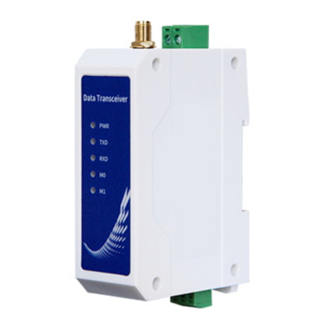
Ebyte E95M-DTU User manual

1
E95M-DTU(400SLxx-xxx)

Chengdu Ebyte Electronic Technology Co.,Ltd. E95M-DTU(400SLxx-xxx) User Manual
Copyright ©2012–2023, Chengdu Ebyte Electronic Technology Co.,Ltd.
2
Contents
Disclaimer .......................................................................................................................................................................3
1 Introduction................................................................................................................................................................. 4
1.1 Brief Introduction ............................................................................................................................................. 4
1.2 Features.............................................................................................................................................................4
1.3 Quick start........................................................................................................................................................ 5
1.4 Description of each department....................................................................................................................... 7
1.5 Installation dimensions...................................................................................................................................10
2. Qualification ............................................................................................................................................................. 11
2.1 Model and specification................................................................................................................................. 11
2.2 General specifications and parameters...........................................................................................................12
2.3 Frequency range and channel number ........................................................................................................... 12
2.4 Transmitting power level ................................................................................................................................12
2.5 Air rate rating..................................................................................................................................................13
2.6 Current parameters ....................................................................................................................................... 13
2.7 Length of receiving and receiving and the subcontracting method.............................................................13
3. Functional detailed explanation............................................................................................................................... 14
3.1 Fixed point launch (162 m) ............................................................................................................................ 14
3.2 Broadcast transmission (16 approx.)..............................................................................................................14
3.3 Broadcast address........................................................................................................................................... 14
3.4 Listen address ................................................................................................................................................. 14
4. work pattern..............................................................................................................................................................15
4.1 Transmission mode (mode 0) ......................................................................................................................... 15
4.2 WOR Mode (Mode 1).................................................................................................................................... 15
4.3 Configuration Mode (Mode 2)....................................................................................................................... 16
5. Register read and write control................................................................................................................................ 16
5.1 Instruction format ........................................................................................................................................... 16
5.2 Register description........................................................................................................................................17
5.3 Factory default parameters ............................................................................................................................. 20
6. AT Directive..............................................................................................................................................................20
6.1 The AT instruction sheet.................................................................................................................................20
6.2 AT parameter resolution ................................................................................................................................. 22
6.3 Notes for serial port upgrade firmware.......................................................................................................... 23
7. Use of the relay network mode................................................................................................................................ 23
8. Description of the upper computer machine configuration ..................................................................................... 24
9. Program the radio stations........................................................................................................................................25
10. The connection diagram in the test and practical application ................................................................................26
11. Related products..................................................................................................................................................... 26
12. Practical applications..............................................................................................................................................27
13. Notes for use...........................................................................................................................................................28
14. Important statement ................................................................................................................................................ 29
Revise the history ......................................................................................................................................................... 29
About us........................................................................................................................................................................29
Chengdu Ebyte Electronic Technology Co.,Ltd. E95M-DTU(400SLxx-xxx) User Manual
Copyright ©2012–2023, Chengdu Ebyte Electronic Technology Co.,Ltd.
3
Disclaimer
EBYTE reserves all rights to this document and the information contained herein.
Products, names, logos and designs described herein may in whole or in part be
subject to intellectual property rights. Reproduction, use, modification or disclosure to
third parties of this document or any part thereof without the express permission of
EBYTE is strictly prohibited.
The information contained herein is provided “as is” and EBYTE assumes no
liability for the use of the information. No warranty, either express or implied, is given,
including but not limited, with respect to the accuracy, correctness, reliability and
fitness for a particular purpose of the information. This document may be revised by
EBYTE at any time. For most recent documents, visit www.cdebyte.com.

Chengdu Ebyte Electronic Technology Co.,Ltd. E95M-DTU(400SLxx-xxx) User Manual
Copyright ©2012–2023, Chengdu Ebyte Electronic Technology Co.,Ltd.
4
1 Introduction
1.1 Brief Introduction
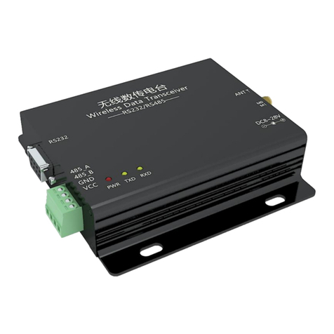
E95M-DTU (400 SLxx-xxx) is a wireless digital radio station using military grade LoRa modulation technology,
with multiple transmission modes, working in (410.125MHz~493.125MHz) band (default 433.125MHz), the station
provides transparent RS485 / RS232 / TTL interface, plastic case, rail installation structure, support 8~28V (DC) wide
voltage, voltage input. LoRa spread frequency technology will bring further communication distance, and have the
advantage of strong anti-interference ability.
Wireless digital radio as a kind of communication media, and optical fiber, microwave, open line, have certain scope
of application: it provides some special conditions of private network monitoring signal of real-time and reliable data
transmission, with low cost, convenient installation and maintenance, shooting ability, flexible network structure, far
coverage characteristics, suitable for point and scattered, complex geographical environment, and PLC, RTU, rainfall
gauge, liquid level meter data terminal.
1.2 Features
★Using the latest LoRa technology, than the traditional LoRa digital radio distance is farther, more powerful
performance;
★Support serial port upgrade firmware, update firmware is more convenient;
★Support AT instruction, it is more convenient to use;
★Ultra-small volume, size of 80 * 28 * 27mm, easy and quick installation;
★E95M-DTU (400SL22-xxx) is up to 5 Km under ideal conditions;
★E95M-DTU (400SL30-xxx) is up to 10 Km under ideal conditions;
★With data encryption, the subcontract length can be set;
★Using flame retardant plastic shell, guide rail type installation structure, convenient and efficient installation;
★Using hidden button to switch the working mode, to avoid false triggering, the equipment operation is more reliable;
★Simple and efficient power supply design, support the power supply distribution device or voltage line mode,
support 8~28V (DC) power supply;
★The transmitting power is 22 / 30 dBm, and supports multi-stage adjustable, all technical indicators meet the
industrial standards;
★Support for 2.4K~62.5Kbps of data transmission rate;
★Support for Modbus protocol transmission;
★Support RSSI signal strength indication function for assessing signal quality, improving communication network and
ranging;
★Support LBT function, the station automatically sends according to the current ambient noise intensity. Greatly
improve the communication success rate of radio stations in the harsh environment;
★Support for wireless transmission of command data packet, remote configuration or reading of radio station
parameters;
★Support the communication key function, and effectively prevent the data from being intercepted;
★It can realize the multi-stage relay networking, effectively expand the communication distance, and realize the

Chengdu Ebyte Electronic Technology Co.,Ltd. E95M-DTU(400SLxx-xxx) User Manual
Copyright ©2012–2023, Chengdu Ebyte Electronic Technology Co.,Ltd.
5
ultra-long distance communication;
★Working temperature range: -40℃ ~ + 85℃, adapt to a variety of harsh working environment, real industrial-grade
products;
★Power reverse connection protection, adoptive protection, antenna surge protection and other multiple protection
functions, greatly increase the reliability of the station;
★Communication ports and power supply interfaces shall be isolated with high protection;
★Powerful software functions, all parameters can be programmed by setting: such as power, frequency, air rate,
address ID, etc.;
★Built-in watchdog, and precise time layout, in the event of abnormalities, the station will automatically restart, and
can continue to work according to the previous parameter settings.
1.3 Quick start
1You need to prepare two E95M-DTU (400 SLxx-xxx)
2First, install the antenna to the digital radio station, and then install the power supply. The user selects the
power adapter according to the need.

Chengdu Ebyte Electronic Technology Co.,Ltd. E95M-DTU(400SLxx-xxx) User Manual
Copyright ©2012–2023, Chengdu Ebyte Electronic Technology Co.,Ltd.
6
3Using USB to RS 235 or other means;
4Start two serial port debugging assistant, select serial port port rate of 9600bps (default), check mode of 8N1,
can achieve serial port transmission;
5If the customer needs to switch the working mode, it can switch the different working modes (M0 indicator
light, M1 indicator light) through the Mode button control. Press the Mode button once for about 1ms to
switch the mode once. Details of the mode switching are shown in the following table:
No.
Class
M1
M0
Note
pattern 0
Through
transmission
mode
light
goes out
light
goes out
Serial port open, wireless open, transparent transmission
(factory default mode), support special command air
configuration.
pattern 1
WOR pattern
light
goes out
light on
Can be defined as WOR sender and WOR receiver, support
aerial wake up
pattern 2
Configuration
mode
light on
light
goes out
The user accthe register through the serial port to control the
working status of the station. The user can configure the station

Chengdu Ebyte Electronic Technology Co.,Ltd. E95M-DTU(400SLxx-xxx) User Manual
Copyright ©2012–2023, Chengdu Ebyte Electronic Technology Co.,Ltd.
7
through the upper computer configuration software.
Note: The radio station has the function of power loss saving mode (the default setting is to transmission mode).
The user needs to switch the corresponding mode according to M1 and M0 indicators (effective immediately).
1.4 Description of each department
1.4.1 RS485 interface
No.
Name
Function
Description
1
PWR
power light
Light ates when power is on.
2
T/R
Send / receive the
indicator light
Flash light is red when sending data and green when
receiving data.
3
MO
Mode indicator light
Operating mode indicator light.
4
M1
Mode indicator light
Operating mode indicator light.
5
Mode
Mode switch button
Working mode switching control.
6
G
GND
Ground.
7
A
The RS485 signal A
Standard RS485 interface.
8
B
The RS485 signal B
Standard RS485 interface.
9
+
VCC
DC power input port, voltage line port.
10
-
GND
DC power input port, voltage line port.
11
ANT
radio frequency
interface
SMA-K,External thread inner hole.
★Note: When the radio station is connected to multiple devices, but not with a single device, try to parallel 120 Ω
resistance between terminal 485_A and 485_B terminals.
★E95M-DTU (400 SLxx-xxx) can be powered by 8~28V (DC) power supply, and the wiring port is connected by a
terminal (2 Pin).

Chengdu Ebyte Electronic Technology Co.,Ltd. E95M-DTU(400SLxx-xxx) User Manual
Copyright ©2012–2023, Chengdu Ebyte Electronic Technology Co.,Ltd.
8
1.4.2 RS232 interface
No.
Name
Function
Description
1
PWR
Power light
Light ates when power is on.
2
T/R
Send / receive the
indicator light
Flash light is red when sending data and green when
receiving data.
3
MO
Mode indicator light
Operating mode indicator light.
4
M1
Mode indicator light
Operating mode indicator light.
5
Mode
Mode switch button
Working mode switching control.
6
G
Signal ground
Anti-interference, grounding.
7
T
The RS232 bus TX
interface
RS232 interface The TX interface is connected to the
device RX interface.
8
R
The RS232 bus RX
interface
RS232 interface The RX interface is connected to the
device TX interface.
9
+
VCC
DC power input port, voltage line port.
10
-
GND
DC power input port, voltage line port.
11
ANT
Radio frequency
interface
SMA-K,External thread inner hole.
★E95M-DTU (400 SLxx-xxx) can be powered by 8~28V (DC) power supply, and the wiring port is connected by a
terminal (2 Pin).

Chengdu Ebyte Electronic Technology Co.,Ltd. E95M-DTU(400SLxx-xxx) User Manual
Copyright ©2012–2023, Chengdu Ebyte Electronic Technology Co.,Ltd.
9
1.4.3 TTL interface
No.
Name
Function
Description
1
PWR
Power light
Light ates when power is on.
2
T/R
Send / receive the
indicator light
Flash light is red when sending data and green when
receiving data.
3
MO
Mode indicator light
Operating mode indicator light.
4
M1
Mode indicator light
Operating mode indicator light.
5
Mode
Mode switch button
Working mode switching control.
6
G
Signal ground
Anti-interference, grounding.
7
T
The TTL bus TX
interface
RS232 interface The TX interface is connected to the
device RX interface.
8
R
The TTL bus RX
interface
RS232 interface The RX interface is connected to the
device TX interface.
9
+
VCC
DC power input port, voltage line port.
10
-
GND
DC power input port, voltage line port.
11
ANT
Radio frequency
interface
SMA-K,External thread inner hole.
★E95M-DTU (400 SLxx-xxx) can be powered by 8~28V (DC) power supply, and the wiring port is connected by a
terminal (2 Pin).

Chengdu Ebyte Electronic Technology Co.,Ltd. E95M-DTU(400SLxx-xxx) User Manual
Copyright ©2012–2023, Chengdu Ebyte Electronic Technology Co.,Ltd.
10
1.5 Installation dimensions

Chengdu Ebyte Electronic Technology Co.,Ltd. E95M-DTU(400SLxx-xxx) User Manual
Copyright ©2012–2023, Chengdu Ebyte Electronic Technology Co.,Ltd.
11
2. Qualification
2.1 Model and specification
Model
Frequency
Transmitting
power
Reference
distance
Specification
Application
MHz
dBm
km
E95M
-DTU(400SL22-485)
410.125 ~
493.125
22
5
New generation of
LoRa frequency
expansion, DC power
supply
Suitable for distant,
vulnerable environments.
E95M -DTU(400SL
22-232)
410.125 ~
493.125
22
5
New generation of
LoRa frequency
expansion, DC power
supply
Suitable for distant,
vulnerable environments.
E95M -DTU(400SL
30-485)
410.125 ~
493.125
30
10
New generation of
LoRa frequency
expansion, DC power
supply
Suitable for distant,
vulnerable environments.
E95M -DTU(400SL
30-232)
410.125 ~
493.125
30
10
New generation of
LoRa frequency
expansion, DC power
supply
Suitable for distant,
vulnerable environments.
E95-DTU(400SL22-TTL )
410.125 ~
493.125
22
5
The new generation of
LoRa frequency
expansion, DC power
supply, isolated
version
Suitable for long
distance, vulnerable to
interference
environment, high
protection
E95-DTU(400SL
30-TTL )
410.125 ~
493.125
30
10
The new generation of
LoRa frequency
expansion, DC power
supply, isolated
version
Suitable for long
distance, vulnerable to
interference
environment, high
protection
★Note: In sunny weather, no shelter, 12V / 1A power supply, 5 dBi suction cup antenna, the antenna is 2 meters away
from the ground height, using the factory default parameters.

Chengdu Ebyte Electronic Technology Co.,Ltd. E95M-DTU(400SLxx-xxx) User Manual
Copyright ©2012–2023, Chengdu Ebyte Electronic Technology Co.,Ltd.
12
2.2 General specifications and parameters
No.
Item
Specifications
Description
1
product size
80*28*27 mm
See installation size for details
2
Product weight
32 g
Weight tolerance of 2g
3
working
temperature
-40℃~+85℃
technical grade
4
voltage range
8~28V (DC )
12V or 24V
5
communication
interface
RS485/RS232/TTL
RS485, RS232, TTL three choose one, subject to the physical
identification of the product
6
Baud rate
Factory default: 9600
The Baud rate range is from 1200 to 115200
7
address code
Factory default 0
A total of 65,536 address codes can be set
2.3 Frequency range and channel number
Model
Frequency
Transmitting power
Reference
distance
Specification
MHz
dBm
km
E95M -DTU(400SLxx
-xxx )
433.125M
410.125~493.125M
1M
84, Half duplex
★Note: In the same area, use multiple sets of transmission stations to communicate one to one at the same time. It is
suggested that the channel interval be set above 2 MHz.
2.4 Transmitting power level
Model
22dBm / 30dBm
17dBm / 27dBm
13dBm / 24dBm
10dBm / 21dBm
E95M -DTU(400SLxx
-xxx )
Factory default
√
√
√
★Note: The lower the transmission power is, the closer the transmission distance is, but the working current will not
decrease in the same proportion, so it is recommended to use the maximum transmission power.

Chengdu Ebyte Electronic Technology Co.,Ltd. E95M-DTU(400SLxx-xxx) User Manual
Copyright ©2012–2023, Chengdu Ebyte Electronic Technology Co.,Ltd.
13
2.5 Air rate rating
Model
Default air rate
Equal series
Air rate grade
bps
k bps
E95M -DTU(400SLxx-xxx )
2.4k
6
2.4、4.8、9.6、19.2、38.4、62.5
★Note: The higher the air speed setting, the faster the transmission rate, and the closer the transmission distance; so if
the rate meets the usage requirements, the lower the air speed, the better.
2.6 Current parameters
Model
Emission current mA
Waiting current mA
12V
24V
12V
24V
E95M -DTU(400SL
22-xxx )
45
26
10
7
E95M -DTU(400SL
30-xxx )
250
125
9
5
★Note: It is recommended to retain more than 50% of the current margin when selecting the power supply, which is
conducive to the long-term and stable operation of the radio station.
2.7 Length of receiving and receiving and the subcontracting method
ts
Cache size
Subcontracting method
E95M -DTU(400SLxx
-xxx )
1000 Bytes
Can be sent by instruction subcontracting 32 / 64 / 128 /
240 bytes
★pay attention to:
1. If the single received data of the radio station is greater than the single package capacity, the excess data will be automatically
allocated to the second transmission until the transmission is completed;
2. Single single received data cannot be greater than the cache capacity.

Chengdu Ebyte Electronic Technology Co.,Ltd. E95M-DTU(400SLxx-xxx) User Manual
Copyright ©2012–2023, Chengdu Ebyte Electronic Technology Co.,Ltd.
14
3. Functional detailed explanation
3.1 Fixed point launch (162 m)
3.2 Broadcast transmission (16 approx.)
3.3 Broadcast address
Example: Set the station A address to 0xFFFF and the channel to 0x04.
When station A is used as transmission (the same mode, transparent transmission mode), all receiving stations under the 0x04
channel can receive data to achieve the purpose of broadcasting.
3.4 Listen address
Example: Set the station A address to 0xFFFF and the channel to 0x04.

Chengdu Ebyte Electronic Technology Co.,Ltd. E95M-DTU(400SLxx-xxx) User Manual
Copyright ©2012–2023, Chengdu Ebyte Electronic Technology Co.,Ltd.
15
When station A is received, it can receive all the data under the 0x04 channel to achieve the purpose of listening.
4. work pattern
E95-DTU has three working modes. When there is no harsh low power consumption demand, it is recommended to configure
the radio station as the transparent transmission mode (mode 0);
The default setting of the station is transmission mode (mode 0).
order
number
class
M1
M0
explanatory note
pattern 0
Through
transmission
mode
light
goes out
light
goes out
Serial port open, wireless open, transparent transmission
(factory default mode), support special command air
configuration.
pattern 1
WOR pattern
light
goes out
light on
Can be defined as WOR sender and WOR receiver, support
aerial wake up
pattern 2
Configuration
mode
light on
light
goes out
The user accthe register through the serial port to control the
working status of the station. The user can configure the station
through the upper computer configuration software.
Note: If no low power requirements, no concern about WOR mode (mode 1).
4.1 Transmission mode (mode 0)
type
When the M0 indicator is out, the M1 indicator is out and the station works in mode 0
launch
Users can enter the data through the serial port, and the radio station will start the wireless transmission.
receive
The radio wireless reception function is turned on, and it will be output through the serial port TXD pin
after receiving the wireless data.
4.2 WOR Mode (Mode 1)
type
When the M0 indicator is on, the M1 indicator is off and the station works in mode 1
launch
When defined as the transmitting side, the wake-up code is automatically added for a certain time before
launch
receive
Data can be received normally, and the receiving function is equivalent to mode 0

Chengdu Ebyte Electronic Technology Co.,Ltd. E95M-DTU(400SLxx-xxx) User Manual
Copyright ©2012–2023, Chengdu Ebyte Electronic Technology Co.,Ltd.
16
4.3 Configuration Mode (Mode 2)
type
When the M0 indicator is off, the M1 indicator lights on and the station works in mode 2
launch
Wireless configuration is available
receive
Wireless configuration is available
configure
The user can access the register to configure the radio operating status
5. Register read and write control
5.1 Instruction format
Under the configuration mode (mode 2: M 1 = OFF, M 0 = ON), the supported instruction list is as follows (when setting, only
9600,8N1 format is supported):
orde
r
num
ber
instruction format
define
1
Set the register
Instructions: C0 + starting address + length + parameter
Response: C1 + starting address + length + parameter
Example 1: The configuration channel is 0x09
Command start address length parameter
Send to: C0 05 01 09
Return: C1 05 01 09
Example 2: simultaneously configure the module address (0x1234), network address (0x00), serial
port (9600 8N1), empty speed (2.4K)
Send to: C0 00 04 12 34 00 60
Return: C1 00 04 12 34 00 60
2
Read the register
Instructions: C1 + starting address + length
Response: C1 + starting address + length + parameter
Example 1: Read the access channel
Command start address length parameter
Send to: C1 05 01
Return: C1 05 01 09
Example 2: Read the module address, network address, serial port, and empty speed
simultaneously
Send to: C1 00 04
Return: C1 00 04 12 34 00 60
3
Set up the temporary
register
Instructions: C2 + starting address + length + parameter
Response: C1 + starting address + length + parameter
Example 1: The configuration channel is 0x09
Command start address length parameter
Send to: C2 05 01 09
Return: C1 05 01 09

Chengdu Ebyte Electronic Technology Co.,Ltd. E95M-DTU(400SLxx-xxx) User Manual
Copyright ©2012–2023, Chengdu Ebyte Electronic Technology Co.,Ltd.
17
Example 2: simultaneously configure the module address (0x1234), network address (0x00), serial
port (9600 8N1), empty speed (2.4K)
Send to: C2 00 04 12 34 00 60
Return: C1 00 04 12 34 00 60
4
Wireless
configuration
Instruction: CF CF + General instruction
Response: CF CF + conventional response
Example 1: The wireless configuration channel is 0x09
Wireless command header command starting address length parameter
Send to: CF CF C0 05 01 09
Return: CF CF C1 05 01 09
Example 2: wireless simultaneous configuration module address (0x1234), network address
(0x00), serial port (9600 8N1), and airspeed (2.4K)
Send to: CF CF C0 00 04 12 34 00 60
Return: CF CF C1 00 04 12 34 00 60
5
format error
Format error response
FF FF FF / “=ERR ”
5.2 Register description
order
number
read-w
rite
name
description
remarks
00H
Read /
write
ADDH
ADDH (default 0)
Module address of high and low bytes;
Note: When the module address is equal to FFFF,
it can be used as a broadcast and listening address,
that is, the module will not filter the address
01H
Read /
write
ADDL
ADDL (default 0)
02H
Read /
write
NETID
NETID (default 0)
Network address, used to distinguish networks;
When communicating with each other, set it as the
same.
03H
Read /
write
REG0
7
6
5
UART Serial Rate (bps)
The two modules of mutual communication, the
serial port port rate can be different, the
calibration mode can also be different;
When large data packets are launched
continuously, users need to consider the data
blocking caused by the same port rate, or may
even be lost;
It is generally recommended that the same have
the same the same.
0
0
0
The serial port port rate is 1200
0
0
1
The serial port port rate is 2400
0
1
0
The serial port port rate is 4800
0
1
1
Serial port port rate of 9600
(default)
1
0
0
The serial port port rate is
19200
1
0
1
The serial port port rate is
38400
1
1
0
The serial port port rate is
57600
1
1
1
The serial port port rate is
115200
4
3
Serial check bit
The communication two sides serial port mode
can be different;
0
0
8N1 (by default)
0
1
8O1
1
0
8E1
1
1
8N1 (equivalent to 00)

Chengdu Ebyte Electronic Technology Co.,Ltd. E95M-DTU(400SLxx-xxx) User Manual
Copyright ©2012–2023, Chengdu Ebyte Electronic Technology Co.,Ltd.
18
2
1
0
Wireless aerial rate (bps)
Both parties to communicate, the air rate, must
be the same;
The higher the air rate, the smaller the delay, and a
shorter the transmission distance.
0
0
0
Aerial rate of 2.4k (default)
0
0
1
The air rate is 4.8k
0
1
0
The air rate is 9.6k
0
1
1
Aerial rate 19.2k
1
0
0
Aerial rate 38.4k
1
0
1
Aerial rate 62.5k
04H
Read /
write
REG1
7
6
Subcontract setting
The data sent by the user is less than the
subcontract length, and the serial port output of
the receiving end is presented as uninterrupted
continuous output;
If the data sent by the user is greater than the
subcontract length, the serial port of the receiving
end will subcontract the output.
0
0
240 bytes (by default)
0
1
128 Bytes
1
0
64 Bytes
1
1
32 Bytes
5
The RSSI ambient noise is enabled
When enabled, instruction C0 C1 C2 C3 can read
register in transmission mode or WOR
transmission mode;
Register 0x00: current ambient noise RSSI;
Register 0X01: RSSI last received
(The current channel noise is: dBm = -
(256-RSSI));
Instruction format: C0 C1 C2 C3 + starting
address + read length;
Return: C1 + address + read length + read valid
value; like send C0 C1 C2 C3 00 01
Return to C1 00 01 RSSI (address only starts from
00)
0
Disable (default)
1
start using
4
Software mode switching
If we use our upper position computer
configuration parameters, we will actively close
the bit. If you do not want to use M0 M1 pins to
switch working mode, you can enable this
function, use specific serial instructions to switch
mode.
Format: C0 C1 C2 C3 02 + working mode
Send C0 C1 C2 C3 02 00 to transmission mode
Send the C0 C1 C2 C3 02 01 to switch to the
WOR mode
Send the C0 C1 C2 C3 02 02 to switch to the
configuration mode
Send the C0 C1 C2 C3 02 03 to switch to the
sleep mode
Return: C1 C2 C3 02 + working mode
Note: When this function is enabled, only 9600
baud rate is supported in WOR mode and sleep
mode.
0
Disable (default)
1
start using
3
2
continue to have
1
0
transmitting power
Power and current are nonlinear relationship,
when the maximum power, the power supply
efficiency is the highest;
0
0
22 / 30 dBm (by default)
0
1
17/27dBm

Chengdu Ebyte Electronic Technology Co.,Ltd. E95M-DTU(400SLxx-xxx) User Manual
Copyright ©2012–2023, Chengdu Ebyte Electronic Technology Co.,Ltd.
19
The current will not decrease in equal proportion
with the power decrease.
1
0
13/24dBm
1
1
10/21dBm
05H
Read /
write
REG2
Channel Control (CH)
0-83 each represent a total of 84 channels (900 band
applicable)
Actual frequency = 410.125 + CH * 1M
06H
Read /
write
REG3
7
Enable the RSSI bytes
When enabled, the module receives wireless data
and the output through the serial port TXD will
follow an RSSI strength byte.
0
Disable (default)
1
start using
6
transmission mode
During the fixed-point transmission, the module
will identify the first three bytes of the serial port
data as: address high + address low + channel, and
take it as the wireless transmission target.
0
Transparent transfer (by default)
1
Fixed-point transmission
5
Relay function
After the relay function is enabled, if the target
address is not the module itself, the module will
start a forward;
To prevent data return, it is recommended to work
with fixed point mode; namely, target address and
source address are different.
0
Disable Relay function (default)
1
Enable relay function
4
LBT enable
After enabling, the wireless data will be
monitored before transmission, which can avoid
interference to a certain extent, but may bring data
delay;
The maximum residence time of LBT is 2
seconds, reaching two seconds.
0
Disable (default)
1
start using
3
The WOR mode transceiver control
Only valid for mode 1;
1. In the receiving mode of word, the module can
modify the delay time after wake up, and the
default time is 0;
2. The receiving terminal needs to send instruction
C0 09 02 03 E8 in configuration mode (C0 is a
write command, 09 is the register initiator
address, 02 is the length, 03 E8 is the set delay,
the maximum FFFF is 65535ms, and set to 0, the
wake up delay is closed.)
3. Data can be sent within the delay
0
WOR recipient (default)
Working in WOR listening mode, the listening
cycle see below (WOR cycle), can save a lot of
power consumption.
1
The WOR transmitter party
The module sends and receives open, and adds
a certain time wake code when transmitting
data.
2
1
0
WOR period
Only valid for mode 1;
Cycle T= (1 + WOR) * 500ms, maximum
4000ms, minimum 500ms;
The longer the WOR monitoring interval period,
the lower the average power consumption, but the
greater the data delay;
It must be consistent (very important)
0
0
0
500ms
0
0
1
1000ms
0
1
0
1500ms
0
1
1
2000ms (by default)
1
0
0
2500ms
1
0
1
3000ms
1
1
0
3500ms
1
1
1
4000ms
07H
write
CRYPT
_H
Key High Bytes (default 0)
Write only, read back to 0;
For encryption, to avoid the aerial wireless data
intercepted by similar modules;
These two bytes will be used as the calculation
factor to encrypt the wireless signal in the air.
08H
write
CRYPT
_L
Key Low Bytes (default 0)
80H ~
86H
a slight
pause
PID
Product information is 7 bytes
Use has been suspended for reserved only. Please
refer to the AT + DEVTYPE and AT + FWCODE

Chengdu Ebyte Electronic Technology Co.,Ltd. E95M-DTU(400SLxx-xxx) User Manual
Copyright ©2012–2023, Chengdu Ebyte Electronic Technology Co.,Ltd.
20
in
reading
instructions in Section 9.1.
5.3 Factory default parameters
Factory default
parameter value
C0 00 09 00 00 00 60 00 23 03 00 00
Module model
frequency
address
channel
Air rate
Baud rate
Serial port
format
transmittin
g power
E95M -DTU
(400SL 20-485)
433.125MHz
0x0000
0x 23
2.4kbps
9600
8N1
20dBm
E95M -DTU
(400SL 30-485)
433.125MHz
0x0000
0x 23
2.4kbps
9600
8N1
30dBm
6. AT Directive
AT instructions are used in configuration mode. AT instructions are divided into three categories: command
instruction, setting instruction and query instruction;
Users can go through the words " AT + HELP =?"Query to the AT instruction set supported by the module,
the AT instruction adopts the port rate of 9600 8N0;
When the input parameter exceeds the range, it will be limited. Please do not let the parameter exceed the
range to avoid the unknown situation.
6.1 The AT instruction sheet
command instruction
description
instance
Example description
AT + IAP (Use carefully, see
article 6.3 serial port upgrade
firmware considerations)
Enter the IAP upgrade
mode
AT+IAP
Enter the IAP upgrade
mode
AT+RESET
Equipment restart
AT+RESET
Equipment restart
AT+DEFAULT
Configure the
parameters to restore
the default
And the device
restarted
AT+DEFAULT
Configure the parameters
to restore the default
And the device restarted
Set instructions
description
instance
Example description
AT+UART=baud,parity
Set the port rate and check
AT+UART=3,0
Set the port rate to
9600,8N0
AT+RATE=rate
Set air rate
AT+RATE=7
Set the air rate to 62.5K
This manual suits for next models
1
Table of contents
Other Ebyte Modem manuals

Ebyte
Ebyte NA111 User manual

Ebyte
Ebyte ECAN-W01S User manual

Ebyte
Ebyte E90-DTU User manual

Ebyte
Ebyte E95-DTU User manual

Ebyte
Ebyte 400SL22-GPRS User manual

Ebyte
Ebyte E18-DTU Series User manual

Ebyte
Ebyte E890-470LG12 User manual

Ebyte
Ebyte E90-DTU User manual

Ebyte
Ebyte E840-DTU User manual

Ebyte
Ebyte E800-DTU User manual

Ebyte
Ebyte E180-DTU(Z20-ETH) User manual

Ebyte
Ebyte E840-DTU User manual

Ebyte
Ebyte M31 Series User manual

Ebyte
Ebyte E90-DTU User manual

Ebyte
Ebyte E96-DTU User manual

Ebyte
Ebyte E90-DTU User manual

Ebyte
Ebyte E831-RTU Series User manual

Ebyte
Ebyte E90-DTU User manual

Ebyte
Ebyte E90-DTU User manual

Ebyte
Ebyte ECAN-401S User manual