EC POWER XRGI 15 User manual

INSTALLATION GUIDE
01DOC1043 VERSION 1.0 2018
FOR PROFESSIONALS

XRGI®
- INSTALLATION GUIDE VERSION 1.0 2018
2
1. DOCUMENTATION INFORMATION 4
1.1 ORIGINAL OPERATING INSTRUCTION 4
1.2 APPLICABLE DOCUMENTS 4
1.3 KEEP THE DOCUMENTS 4
1.4 SYMBOLS USED 4
1.5 RATING PLATE 4
1.6 VALIDITY OF THE GUIDE 5
1.7 CE MARKING 5
2. SYSTEM COMPONENTS 6
2.1 MAIN XRGI® SYSTEM COMPONENTS 6
2.1.1 POWER UNIT 7
2.1.2 iQ-CONTROL PANEL 9
2.1.3 Q-HEAT DISTRIBUTOR 10
2.2 XRGI® SYSTEM ACCESSORIES 11
2.2.1 Q-NETWORK 11
2.2.1.1 STORAGE CONTROL 12
2.2.1.2 FLOW MASTER CONTROL 13
2.2.1.3 FLOW MASTER 14
2.2.1.4 BOILER CONTROL 15
2.2.1.5 VPP GATEWAY 16
2.2.1.6 ELECTRIC HEATER CONTROL 17
2.2.1.7 MODBUS GATEWAY 18
2.2.1.8 STORAGE TANK 19
2.2.1.9 LOAD SHARER S 21
3. SAFETY INSTRUCTION 22
3.1 SAFETY AND WARNING INSTRUCTIONS 22
3.1.1 SAFETY AND WARNING SYMBOLS USED 22
3.2 INTENDED USE 22
3.3 GENERAL SAFETY INSTRUCTIONS 24
3.3.1 HANDLING ENGINE OIL 24
3.3.2 ACTIONS WITH SMELL OF GAS IN BUILDINGS 25
3.3.3 ACTIONS WITH FIRE OR IGRESS OF WATER 25
3.3.4 ACTIONS WITH SMELL OF EXHAUST GAS IN BUILDINGS 25
3.3.5 FROST PROTECTION 26
3.3.6 CONTACT HAZARD 26
3.3.7 EXPLOSIVE AND EASILY FLAMMABLE MATERIALS 26
3.3.8 COMBUSTION AIR SUPPLY 26
3.3.9 MODIFICATIONS TO THE XRGI® SYSTEM COMPOUNDS 27
3.3.10 FILLING AND TOP-UP LIQUID 27
3.3.11 PROPERTY DAMAGE CAUSED BY IMPROPER USE OF AND/OR UNSUITABLE TOOLS 27
3.3.12 MODIFICATIONS IN THE VICINITY OF THE XRGI® SYSTEM 28
3.3.13 OPERATION WITH LIQUID GAS 28
3.3.14 WORKING ON THE ELECTRICAL SYSTEM 28
3.3.15 SAFETY EQUIPMENT ON THE XRGI® SYSTEM 29
3.3.16 SAFETY AND WARNING LABELS ON THE XRGI® SYSTEM 29
3.4 REGULATIONS, STANDARDS AND LAWS 30
3.5 WARRANTY INFORMATION 30
3.5.1 RETURN OBLIGATIONS 30
TABLE OF CONTENTS

XRGI®
- INSTALLATION GUIDE VERSION 1.0 2018
3
4. ASSEMBLY 32
4.1 SCOPE OF DELIVERY CHECK – XRGI® SYSTEM 32
4.1.1 XRGI® ORIGINAL ACCESSORIES 32
4.2 TRANSPORT AND HANDLING 32
4.3 INSTALLATION ROOM 33
4.3.1 FOUNDATION 33
4.3.2 ROOM TEMPERATURE/DUST 33
4.3.3 NOISE AND VIBRATION 33
4.3.4 CORROSIVE AMBIENT CONDITIONS 34
4.3.5 REQUIRED AIR INLETS 34
4.3.6 REMOTE DATA MONITORING 34
4.4 DIMENSIONS AND CONNECTIONS 35
4.4.1 XRGI® 6/9-SYSTEM 35
4.4.2 XRGI® 15/20-SYSTEM 38
4.5 REQUIRED MINIMUM CLEARANCES – ASSEMBLY & MAINTENANCE CLEARANCES 41
4.5.1 XRGI® 6/9-SYSTEM 41
4.5.2 XRGI® 15/20-SYSTEM 42
4.6 INSTALLATION OF THE XRGI® SYSTEM 44
4.6.1 SOUND INSULATION 44
5. INSTALLATION 45
5.1 HYDRAULIC INSTALLATION 45
5.1.1 EC POWER STANDARD HYDRAULIC SYSTEM 45
5.1.2 INSTALLATION Q-HEAT DISTRIBUTOR – POWER UNIT 49
5.1.2.1 PRIMARY CIRCUIT – FLOW AND RETURN CONNECTION 49
5.1.3 INSTALLATION Q-HEAT DISTRIBUTOR – STORAGE TANK/CONSUMER NETWORK 50
5.1.3.1 SECONDARY CIRCUIT – FLOW AND RETURN CONNECTION 50
5.1.3.2 EC POWER STORAGE TANK 51
5.2 EXHAUST GAS SIDE INSTALLATION 52
5.2.1 EXTERNAL EXHAUST HEAT EXCHANGER 52
5.3 GAS SIDE INSTALLATION 53
5.3.1 GAS HOSE CONNECTION 53
5.4 ELECTRICAL INSTALLATION 54
5.4.1 POWER UNIT 54
5.4.2 Q-HEAT DISTRIBUTOR 54
5.4.3 iQ-CONTROL PANEL 54
5.4.4 POWER FACTOR CORRECTION 56
5.5 NETWORK INSTALLATION 56
5.5.1 STORAGE CONTROL 56
5.5.2 FLOW MASTER CONTROL 57
5.5.3 FLOW MASTER 57
5.5.4 BOILER CONTROL 58
5.5.5 VPP GATEWAY / ELECTRIC HEATER CONTROL 59
5.5.6 MODBUS GATEWAY 59
5.5.7 LOAD SHARER S 60
TABLE OF CONTENTS

XRGI®
- INSTALLATION GUIDE VERSION 1.0 2018
4
1. DOCUMENTATION INFORMATION
This XRGI® installation guide provides detailed information about the individual XRGI® system components, their functions, assembling
and installation.
It provides important safety instructions that must be complied with when operating the XRGI® system and describes the interplay of
the Power Unit, the Q-Heat Distributor and the iQ-Control Panel as included in the standard scope of delivery. It also describes certain
accessories, the Q-Network modules and the storage tank, which may be required depending in the individual installation.
Please read this XRGI® installation guide carefully before installation and commission.
Only a correct assembling, installation and operation of the XRGI® system according to the specifications from EC POWER ensures proper
functioning and a valid warranty. Please keep this XRGI® installation guide for later reference. EC POWER continuously improves its pro-
ducts and reserves the right to make technical changes and to implement these changes if considered necessary. This means that the
company is not bound to make retrospective changes to already delivered XRGI® systems.
The following information’s are a guide through the entire documentation. In connection with this XRGI® installation guide. In connec-
tion with this XRGI® installation guide, other accompanying documents must be followed. EC POWER cannot take responsibility for any
damages caused by non-compliance with the instructions for the XRGI® system.
1.1 ORIGINAL OPERATING INSTRUCTION
1.2 APPLICABLE DOCUMENTS
1.3 KEEP THE DOCUMENTS
1.4 SYMBOLS USED
1.5 RATING PLATE
This XRGI® installation guide contains original operating instructions in accordance with the Machinery Directive.
When installing the XRGI® system, all installation instructions for additional components and components of the XRGI® system must
be complied with. These installation instructions are attached to the respective components of the XRGI® system and additional
components.
Please note all operating instructions that come with the components of the XRGI® system.
These documents are subject to technical modifications!
Due to the continuous development of the XRGI® systems, illustrations, functional steps and technical data may differ slightly.
Pass on this XRGI® installation guide and all applicable documents to the system operator.
The system operator keeps the XRGI® installation guide and other instructions for future reference so that they are available when
needed.
The following explains the symbols used in the text.
INFO!
Symbol for important and useful information about the issue.
POWER UNIT
The rating plate is located on the back of the Power Unit.
Legend
1Power Unit serial no.
2Type description of the XRGI® system
3Description of the type approval
4Technical data of the Power Unit
5CE marking
1
3
4
2 5
Fig. 1.01 – Power Unit rating plate

XRGI®
- INSTALLATION GUIDE VERSION 1.0 2018
5
1
3
2 4
1
2
3
4
1
With the CE marking, products comply with the essential requirements of the relevant directives in accordance with the rating plate.
Q-HEAT DISTRIBUTOR
The rating plate is located on the inside of the Q-Heat Distributor
below the electronics box.
Legend
1Q-Heat Distributor serial no.
2Type description of the Q-Heat Distributor
3Technical data of the Q-Heat Distributor
4 CE marking
iQ-CONTROL PANEL
The iQ-Control Panel has two rating plates. These are located on the inside
of the iQ-Control Panel door and on the left side of the iQ-Control Panel,
below the main switch disconnector.
Legend
1iQ-Control Panel serial no.
2 Technical data of the iQ-Control Panel
3Type description of the iQ-Control Panel
4XRGI®-ID of the XRGI® system
1.7 CE MARKING
1.6 VALIDITY OF THE GUIDE
This XRGI® installation guide only applies to XRGI® systems with the following article numbers:
■Without additional accessories
■With additional storage tank
Type Article number
XRGI® 6 X060001 / X060002
XRGI® 9 X090001 / X090002
XRGI® 15 X150001 / X150002
XRGI® 20 X200001 / X200002
Fig. 1.02 – Q--Heat Distributor rating plate
Fig. 1.04 – Rating plate iQ-Control Panel
Fig. 1.03 – iQ-Control Panel rating plate

XRGI®
- INSTALLATION GUIDE VERSION 1.0 2018
6
An XRGI® system consists of the following three main components:
POWER UNIT
■Heat production
■Power production
■Safety functions
■Power control
IQCONTROL PANEL
■Connection to the grid
■Electrical safety features
■Control of the XRGI® system
■Status and production display
■Remote data transmission
QHEAT DISTRIBUTOR
■Regulation of the temperature of the engine water
■Connection of the XRGI® system to the storage tank and the central
heating system
■Output of high-efficiency pumps regulated according to current demand
■Creation of storage strategies according to current demand
■Service and error messages in the heating system
2. SYSTEM COMPONENTS
2.1 MAIN XRGI® SYSTEM COMPONENTS
An XRGI® system consists of three main components: the Power Unit, the Q-Heat Distributor and the iQ-Control Panel.
The XRGI® system can be expanded with additional XRGI® accessories: Storage Control, Boiler Control, Flow Master Control, Flow
Master, Electric Heater Control, VPP Gateway, Modbus Gateway, storage tank and Load Sharer S.
Construction of the standard XRGI® systems:
XRGI®6 Power Unit XRGI® 6 – Q20-Heat Distributor – iQ10-Control Panel
XRGI®9 Power Unit XRGI® 9 – Q20-Heat Distributor – iQ10-Control Panel
XRGI®15 Power Unit XRGI® 15 – Q80-Heat Distributor – iQ15-Control Panel
XRGI®20 Power Unit XRGI® 20 – Q80-Heat Distributor – iQ20-Control Panel
Fig. 2.01
Fig. 2.02
Fig. 2.03
Fig. 2.04

XRGI®
- INSTALLATION GUIDE VERSION 1.0 2018
7
A B
C
1 4 52 6
3 7
8/9
10
12
14
13
15
16
18
17
11
Fig. 2.05 - XRGI® 6/9
Fig. 2.06 - XRGI® 6/9
Fig. 2.07 - XRGI® 6/9
2.1.1 POWER UNIT
CONSTRUCTION
Legend:
A Electrical components and safety circuit
B Air filter and mixture control
C Sound- and heat-insulated engine compartment
1 Silencer (integrated)
2 Water-cooled generator
3 Exhaust gas cooler (not visible)
4 Oil sump
5 EC POWER gas engine
6 Oil separator
7 Catalyst (not visible (patented))
8 Primary circuit flow (1“ G)
9 Primary circuit return (1“ G)
10 Electrical connection
11 Exhaust gas connection (twin tube, di = 60 mm, da = 100 mm)
12 Gas connection (½“ G)
13 Air filter
14 Gas safety circuit
15 Cover with gas pressure springs
16 Spark plugs
17 Upright pipe for oil change
18 Oil filter (upright, water-cooled)

XRGI®
- INSTALLATION GUIDE VERSION 1.0 2018
8
C
A B
15
16
17
18
9
8
10
12
13
14
11
C
A B
15
16
17
18
9
8
10
12
13
14
11
1 2 5 4
3 7
61 2 5 4
3 7
6
CONSTRUCTION
Legend:
A Electrical components and safety circuit
B Air filter and mixture control
C Sound- and heat-insulated engine compartment
1 Silencer (integrated)
2 Water-cooled generator
3 Exhaust gas cooler (not visible)
4 Oil sump
5 EC POWER gas engine
6 Oil separator
7 Catalyst (not visible (patented))
8 Primary circuit flow (1¼“ G)
9 Primary circuit return (1¼“ G)
10 Electrical connection
11 Exhaust gas connection (twin tube, di = 60 mm, da = 100 mm)
12 Gas connection: XRGI® 15: ¾“ G – XRGI® 20: ¾“ G
13 Air filter
14 Gas safety circuit
15 Cover with gas pressure springs
16 Spark plugs
17 Upright pipe for oil change
18 Oil filter (upright, water-cooled)
FUNCTION
CONFIGURATION
The Power Unit contains the following main components:
■Engine control
■Cooling circuit
■Mixture control
■Engine electronics
■Gas safety circuit
■Temperature monitoring relay
Here, gas converts into electricity and heat.
The gas setting must only be carried out by authorised persons. This is described in the commissioning instruction. No further adjust-
ments are needed on the engine.
Fig. 2.08 - XRGI®15
Fig. 2.09 - XRGI®15
Fig. 2.10 - XRGI®15
Fig. 2.12 - XRGI®20
Fig. 2.13 - XRGI®20
Fig. 2.11 - XRGI® 20

XRGI®
- INSTALLATION GUIDE VERSION 1.0 2018
9
1 9 3 102
84
5
12
7
11 13
6
1 2 3 4
89
5
13
6
12
7
11
10
14
14
Legend:
1 Contactor
2 Residual current breaker (4P 40A 30mA)
3 Miniature circuit breaker
4 Fan
5 Central Control PCB with integrated modem (not visible)
6 Residual current breaker (1P+N 1A C)
7 Motherboard (not visible)
8 RJ45 connector
9 Transient protection
10 Direct power meter
11 Soft starter
12 Main switch disconnector
13 Network monitoring relay
14 Antenna
2.1.2 IQCONTROL PANEL
CONSTRUCTION
CONFIGURATION
FUNCTION
The iQ-Control Panel is used to operate the XRGI® system.
■Main switch disconnector: Main switch connector masters
on/off switch for the iQ-Control Panel and the Power Unit
INFO: The Q-Heat Distributor is powered separately!
■Soft starter: Starts the generator as an engine
■Auxiliary relay: Extra relay for the soft starter
■RCD type A: Fault protection
■Fuses: Overvoltage protection
■Output meter. measures the electricity produced by the
generator
■ENS relay: N/A protection device
■Motherboard power supply: Supplies 12V to the mainboard
■Motherboard: Communication interface with the Power
Unit and the Q-Heat Distributor
■Central Control PCB with integrated modem system
processor: Sends data to the EC POWER service database
via mobile network
The iQ-Control Panel is mainly responsible for the following:
■System control
■Power regulation
■Power meter (production)
■Hardware and software for the operating strategy
■Data collection and analysis
■Communication with the service database
■Interfaces for external connections
The iQ-Control Panel is operated using its front panel and turned on and off using the main switch disconnector on the left side.
Fig. 2.14 - iQ 10
Fig. 2.15 - iQ 15/20

XRGI®
- INSTALLATION GUIDE VERSION 1.0 2018
10
2
6
5
1
3 4
1
6
5
2
3 4
FUNCTION
CONFIGURATION
The Q-Heat Distributor plays the following role in the XRGI® system:
■Separation of the engine circuit (primary) from the heating
network
■Protection of the primary circuit
■Control of the engine temperature
■Control of the system temperature
■Management of the storage load
■Management of the energy flows
The Q-Heat Distributor separates the engine circuit (Power Unit
cooling water circuit) from the heating system by means of a plate
heat exchanger. In this way, the expansion vessel protects the engine
circuit. The circulation pump for the engine circuit is mounted on the
left of the primary circuit of the Q-Heat Distributor. When the Q-Heat
Distributor is connected to power, the circulation pumps run for 5–10
seconds to check that they are working properly.
The pumps cannot be configured. They start together with the Power
Unit and stop approx. 10–20 minutes after the Power Unit has shut
down. Their power is controlled by the Q-Heat Distributor according
to demand. The storage charge group (on the right of the Q-Heat
Distributor) controls the engine temperature via the mixer and the
speed-controlled circulation pump. The system is designed to maximi-
se the storage charge temperatures (80–85 °C).
The Q-Heat Distributor does not need to be adjusted after assembly.
2.1.3 QHEAT DISTRIBUTOR
Legend:
1Expansion vessel
2RJ45 connector
3Flow and return connection to the Power Unit
4Flow and return connection to the storage tank/consumer network
5Mixer for engine temperature control
6Plate heat exchanger (not visible)
CONSTRUCTION
Fig. 2.16 - Q20
Fig. 2.17 - Q80

XRGI®
- INSTALLATION GUIDE VERSION 1.0 2018
11
2.2 XRGI® SYSTEM ACCESSORIES
2.2.1 QNETWORK
The XRGI® control system is based on two logical networks:
■Q-net Control (control network)
■Q-net Heat (heat network)
Both systems use the conventional hierarchical master/slave strategy, with the master controller alone being able to access the shared
resources unsolicited. The slave controller cannot access the shared resources of its own accord; it has to wait until it is asked by the
master controller.
All network modules have two RJ45 ports per board. The iQ-Control Panel is the master for the control network and hence for the
Power Unit and the Q-Heat Distributor. The Q-Heat Distributor is the master for the heat network and thus the interface between the
two logical networks. The Q-Heat Distributor therefore has two boards and four ports.
Each RJ45 port has two LEDs (e.g., the Storage Control is shown below):
The LED on the left (orange) indicates the connection status:
■LED off = System off
■LED Continuously on = Connected
■LED Flashing = Communication
The LED on the right (green) indicates the operating status:
■LED green = Everything OK
■LED red = Unit is connected to the wrong network or there is no space for more units
■LED flashing red = Error (refer to relevant product specifications)
The control network consists of the iQ-Control Panel (master), the Q-Heat Distributor and the gas safety circuit (both slaves).
The heat network consists of the Q-Heat Distributor (master) and the downstream members: Storage Control, Flow Master Control
and Boiler Control (all slaves). The members belonging to the network are looped via the Q-Network cable in series (not star-cabled).
Each Q-Heat Distributor can control up to 20 slaves, although there can only be one Flow Master Control in the network, but multiple
Storage Controls. Installations with multiple Power Units have their Q-Network modules linked by a Q-Network cable.
The iQ-Control Panel and Q-Heat Distributor continuously request data from network members every few seconds and update their
functionality. This means that a Storage Control can be added to the network during operation, for example.
Available Q-Network modules:
■Q-Network Storage Control (storage control)
■Q-Network Flow Master Control (discharge control)
■Q-Network Boiler Control (boiler activation)
■Q-Network VPP Control (virtual power plant control)
■Q-Network Electric Heater Control
■Q-Network Modbus Gateway
■Q-Network storage tank with external Storage Control
Fig. 2.18

XRGI®
- INSTALLATION GUIDE VERSION 1.0 2018
12
2.2.1.1 S T O R A G E C O N T R O L
The Storage Control organises the management of the storage tank (filling and emptying). Each XRGI® system needs at least one
Storage Control.
Temperature sensors determine the separation layer between the cold return and warm flow and from this calculate the required
storage level and/or the required residual heat volume for the selected operating strategy from this.
A clear separation between the cold return and warm flow by the separation layer is crucial for a high capacity in the storage tank and
an optimum operation. This separation is ensured by the EC POWER storage tank.
The storage tank management is based on the following sequence and criteria:
1. Ensure that the XRGI® system runs for a minimum amount of time
Only start up the XRGI® system when the storage tank can accommodate a minimum heat production.
2. Use the XRGI® system to meet the peak heating loads in the building
Start up the XRGI® system when the storage tank is not completely empty. The XRGI® system‘s heat production and the
volume of residual heat from the storage tank reduce the heat production in the boiler and extend the runtime of the XRGI®
system.
3. Enabling a power-controlled operation (either based on electricity need and/or electricity price)
By storing the heat in the storage tank for later consumption, electricity production is ensured, even when no heat is needed
but electricity is.
The reserve capacities determined by the Storage Control vary according to the season
and the extent of the heat demand. In the colder months and/or at times of high demand
for heat, a higher volume of residual heat is retained in the storage tank (to allow for cover-
age of peaks of heat load). A smaller volume of residual heat is maintained in the warmer
months (minimum runtime of XRGI® system, power-controlled operation). The Storage
Control continuously determines the optimum residual heat volume based on demand
and consumer behaviour.
The Storage Control is a self-configuring sensor system. The sequence of the storage tanks
is automatically detected when they are charged for the first time. The sequence of the
sensors within the storage tank is very important: It has to start at the top with sensor 1
and run down to sensor 4.
A Storage Control is needed if no EC POWER storage tank is used.
When using an EC POWER storage tank, the required storage controls are included.
Use a minimum of one Storage Control with four temperature sensors per cubic meter of storage tank volume.
SCOPE OF DELIVERY Modules Storage Control unit, four PT100 sensors, one Q-Network cable
CABLE DIMENSIONS PT100 sensor cable m 3
Q-Network cable m 5
DIMENSIONS
AND WEIGHT
Dimensions, W x H x D mm 130 x 35 x 80
Weight kg 0.165
Fig. 2.19 - Storage Control
Fig. 2.20

XRGI®
- INSTALLATION GUIDE VERSION 1.0 2018
13
2.2.1.2 F L O W M A S T E R C O N T R O L
The Flow Master Control regulates the heat output from the XRGI® system and the storage tank (temperature level VL between 80
and 85 °C) into the heating system by means of the controllable pump and the valve of the Flow Master so that the required flow
temperature Tf (= setpoint) is reached. The setpoint for Tf is set on the iQ-Control Panel.
Please note:
Once the actual temperature Tf falls below the setpoint, the controllable pump in the Flow Master will start and the control valve will
open. 85 °C hot water from the XRGI® system and/or storage tank will be mixed into in the heating network until the setpoint Tf is
reached.The discharge from the storage tank will be maximised with the power that is possible according to the installed Flow Master.
The temperature sensor Tb ensures that not too much 85 °C warm water is injected into the heating network by the adjustable pump
(to prevent backflow). The temperature sensor Tr detects the temperature of the return water in the system. If the temperature of the
system‘s return water is too high for engine cooling, the Flow Master will stop the injection and the return heating water will bypass
the XRGI® system.
When the storage tank is empty (because of continuously higher heat demand to the heating network than the heat production in
the XRGI® system), the discharge from the storage tank will sometimes stop in order to fill the storage tank. In this case, the heat supply
is automatically supplied by the boiler (the boiler will be activated if the temperature falls below the flow temperature at setpoint
VL in the boiler). While the storage tank is being refilled, the boiler as the sole source of heat in the system prevents the boiler from
constantly switching on and off and, in this way, saves energy.
When the storage tank is sufficiently refilled, it automatically begins to discharge heat into the system again and boiler operation
stops, but only if the heat in the XRGI® system and the storage tank with the installed Flow Master is sufficient to meet demand.
Tf is set to a maximum of 79.9 °C and should always be higher than the maximum boiler temperature so that the
XRGI® system can deliver the base heat load (∆ 5 K is sufficient).
SCOPE OF DELIVERY Modules Flow Master Control unit, four PT100 sensors, one Q-Network cable
CABLE DIMENSIONS PT100 sensor cable m 3
Q-Network cable m 5
DIMENSIONS
AND WEIGHT
Dimensions, W x H x D mm 180 x 60 x 130
Weight kg 0.5
Fig. 2.21 - Flow Master Control

XRGI®
- INSTALLATION GUIDE VERSION 1.0 2018
14
The Flow Master feeds the heat from the XRGI® system and from the storage tank into the consumer circuit. In the short term, this
allows significantly higher heating capacity on the consumer side than with the installed XRGI® heating line. With this, heat demand
peaks can be handled by the XRGI® system, thus extending its production time and increasing heating capacity.
Four models are currently available that can operate at a ∆T of 20 K with a heat output of 50, 150, 250 or 350 kW. The desired flow
temperatures (up to a maximum of 79.9 °C) are constantly available. The injectable heat output is adjusted automatically depending
on the return temperature from the property‘s network. The decision about which Flow Master to be used with Flow Master Control
is determined according to the building conditions and the consumption habits.
When using a Flow Master with a Flow Master Control, the instructions on the temperature sensors, the injection line and the sizing
of the heating pipes are to be complied with to ensure correct operation.
SCOPE OF DELIVERY FM type (temperature controller, class II = 2 %) FM 50 FM 150 FM 250 FM 350
Modules Flow Master, Flow Master Control Unit, four PT100 sensors, one Q-Network cable,
one valve control cable, one pump control cable and one power cable
DATA Pump UPM3
15-75 130
UPMXL GEO
25-125 180
Magna3
50-60 F 220
Magna3
50-60 F 240
Flow connection G¾" 1 ¼" 1 ½" 2"
Temperature sensor PT100 (5 x 40 mm) PT100 (5 x 40 mm) PT100 (5 x 40 mm) PT100 (5 x 40 mm)
Maximum flow volume m3/h 2.2 6.5 10.8 15.1
Thermal capacity kW 50 150 250 350
∆T (with a return of 60–65 °C) °C 20 20 20 20
CABLE DIMENSIONS PT100 sensor cable m 3
Valve control cable m 1.8
Pump control cable m 1.8
Power cable m1.8
Q-Network cable m 5
DIMENSIONS
AND WEIGHT
Dimensions, W x H x D mm 157 x 120 x 323 181 x 196 x 411 297 x 221 x 483 407 x 273 x 512
Weight kg 2.9 5.4 17.2 27.1
2.2.1.3 F L O W M A S T E R
Fig. 2.22 - Flow Master

XRGI®
- INSTALLATION GUIDE VERSION 1.0 2018
15
2.2.1.4 B O I L E R C O N T R O L
The Boiler Control ensures the optimum operation of the XRGI® system and the peak load boiler when the XRGI® system is operated
hydraulically via the storage tank parallel to the boiler.
The boiler control activates the boiler to produce heat via a potential free contact if the consumption is larger than the heat producti-
on of the XRGI® system and the storage tank is almost empty.The boiler is disabled as soon as the heat production in the XRGI® system
exceeds the consumption.
If the heat consumption is higher than the heat generation in the XRGI® system in the long term, the top storage sensor S1 will
become cold. Then the boiler control enables the boiler to produce heat until the storage sensor second from the top S2 registers a
sufficient temperature. When this happens, the Boiler Control disables the boiler again.
The additional installation of the Boiler Control ensures that the boiler will only be switched on when needed and, in this way, the
operating time of the XRGI® system will not be reduced. This is particularly important with parallel circuits and warm water provision
so that the boiler does not start up unnecessarily, although the heat production of the XRGI® system and the storage volume are
sufficient to deliver heat.
After the assembling of the Boiler Control, it does not require further adjustments.
The Boiler Control is controlled according to the top two Storage Control temperature sensors in the storage tank
and the predetermined flow temperature Tf.
SCOPE OF DELIVERY Modules Boiler Control unit, one green system plug, one Q-Network cable
CABLE DIMENSIONS Q-Network cable m10
DIMENSIONS
AND WEIGHT
Dimensions, W x H x D mm 130 x 35 x 80
Weight kg 0.165
Fig. 2.23 - Boiler Control
Fig. 2.24

XRGI®
- INSTALLATION GUIDE VERSION 1.0 2018
16
T1
T2
T3
T4
The control centre (central control of the virtual power plant) communicates the required operating strategy for the XRGI® system.
The XRGI® controller guarantees the operating mode (on, off or modulating mode) on the XRGI® system. Here, the storage tank plays
a key role and enables the management of the storage tank to be separated from the heat and the power production. The EC POWER
control individually defines the optimum mode of operation for each property based on:
■level of the storage tank
■actual heat demand
If no operating strategy is communicated by the control centre, the XRGI® system operates heat-controlled.
The EC POWER solution works on the basis of the operating status of the decentralised installed system and thus guarantees:
■Simple and stable supply (without safety reserves for emergency heat demand)
■Completion of the operating strategy by individual and selective emptying of the storage tank
■No incorrect forecasts of the heat demand and the required expertise for this
■Simple set-up of a virtual power plant at minimal cost
■Fast achievement of an efficient virtual power plant even with smaller systems
SCOPE OF DELIVERY Modules VPP Gateway unit, one green system plug
DIMENSIONS
AND WEIGHT
Dimensions, W x H x D mm 130 x 35 x 80
Weight kg 0.165
The VPP Control is activated by means of potential-free contacts.This external control is independent of the manufacturer. For in-stan-
ce, it can be provided by the building’s own BMS, a small controller or a remote data transmission. The control voltage from the VPP
Control must be 24V and the cable cross-section must be 6 × 0.8 mm2. The control cable is connected to the VPP Control by the
supplied system plug (green).
The VPP Control is integrated into the Q-Network by the supplied CAT6 quality
RJ45 patch cable. A longer cable of the same quality can be provided on-site if the
supplied cable of 3 metres is not long enough. The VPP Control must be integrated
on the control side (i.e., the VPP Control can be connected either to the Power Unit
or to the iQ-Control Panel). Connection to the iQ-Control Panel is preferable.
OPERATING MODES
All the required functions needed for the operation of a virtual power plant can be provided with only
five operating modes.
SIGNAL 1: XRGI® system runs at„maximum“
The XRGI® system starts up when sensor T2 signals„cold“. It works until no further system cooling is pos-
sible (i.e., the engine constantly exceeds the outlet temperature of 95 °C).
SIGNAL 2: XRGI® system runs at„minimum“
The XRGI® system starts up when sensor T1 is„cold“. The controller tries to keep sensor T1 warm by swit-
ching between small load or modulating operation and maximum power. Thus, the XRGI® system largely
ensures the provision of heat without filling up the storage tank. The XRGI® system stops at the latest
when T1 signals„warm“.
SIGNAL 3: No production by the XRGI® system
The XRGI® system and one available electric heater, if fitted, remain switched off. The heat generation
must be ensured by an additional heat generator, controlled by a controller independent of the VPP.
SIGNAL 4: Electric heater runs at„minimum“
The electric heater starts up when sensor T1 is cold. The controller tries to keep the sensor T1 warm. Thus,
the electric heater largely ensures the provision of heat without filling up the storage tank.
SIGNAL 5: Electric heater runs at„maximum“
The electric heater starts up when sensor T2 signals „cold“. It works until the storage tank has been fully
charged.
2.2.1.5 V P P G AT E W AY
Abb. 2.25 - VPP Gateway
Fig. 2.27 - Electrical connection
Fig. 2.26

XRGI®
- INSTALLATION GUIDE VERSION 1.0 2018
17
2.2.1.6 E L E C T R I C H E AT E R C O N T R O L
The Electric Heater Control must be integrated into the storage tank circuit together with a 30 kW-E heater with pump and three-way
mixing valve in order to charge the storage tank.
The Electric Heater Control relay responds when electrical heating is wanted. Thus, water can to be heated to 85 °C with power. The
Electric Heater Control relay is switched off as standard.
This functionality acts together with the VPP module.
SCOPE OF DELIVERY Modules Electric Heater Control unit, one control cable
CABLE DIMENSIONS Control cable m 3
Cable dimensions mm23 x 0.5
DIMENSIONS
AND WEIGHT
Dimensions, W x H x D mm 130 x 35 x 80
Weight kg 0.165
Fig. 2.28 - Electric Heater Control
Fig. 2.29

XRGI®
- INSTALLATION GUIDE VERSION 1.0 2018
18
2.2.1.7 M O D B U S G AT E W AY
The Modbus Gateway has two main functions:
READING INFORMATION
Information is immediately available after connection to the network (without further equipment).
EXTERNAL CONTROL OF THE XRGI® SYSTEM
After the initialisation of the XRGI® control software, the operation of the XRGI® system can be controlled by an external control. After
the initialisation of the external control, the current software version of the XRGI® system is operated in heat-controlled mode without
external control (the other operating modes will be available in the future).
The description of the interfaces includes details on the main functions.
REQUIREMENTS FOR USE
The Modbus Gateway can only be used if the Central Control PCB with integrated modem is fitted in the iQ-Control Panel (the modem
is separate with the old Central Control PCB). XRGI® systems with older Central Control PCB’s can be upgraded. EC POWER provides
an upgrade kit.
The control must have the software version 1.11.5 or higher. A software update is needed if an older software version is fitted in an
XRGI® system.
CONNECTION TO EXTERNAL SYSTEMS
External systems can be connected to the RS485 bus via the Modbus RTU.
The data registers within the Modbus protocol are kept up to date by the EC POWER control software and/or read by the external
control.
The description of the interfaces includes details about programming the external connection.
SCOPE OF DELIVERY Module Modbus Gateway unit, one green system plug, one Q-Network cable
CABLE DIMENSIONS Q-Network cable m 5
DIMENSIONS
AND WEIGHT
Dimensions, W x H x D mm 130 x 35 x 80
Weight kg 0.165
Fig. 2.30 - Modbus Gateway

XRGI®
- INSTALLATION GUIDE VERSION 1.0 2018
19
2.2.1.8 S T O R A G E T A N K
SCOPE OF
DELIVERY
Modules Storage Tank 500 l
including one
storage control
Storage Tank 800 l
including one
storage control
Storage Tank 1,000 l
including two
storage control
OUTPUT Heat capacity (at 40 °C temperature difference) kWh 22 35.2 44
Heat loss W 100 116 136
Qst kWh/24h 2.408 2.772 3.271
OPERATING
PARAMETERS
Max. operating pressure bar 6 6 6
Max. operating temperature ºC 95 95 95
CONNECTIONS Flow G2“ 2“ 3"
Return G 2“ 2“ 3“
Drain G 1“ 1“ 1“
Air vent G ½“ ½“ ½“
INSULATION Jacket (PU hard) mm 70 95 95
Lid (PU hard) mm 70 95 95
Base (PU hard) mm 50 50 50
DIMENSIONS
AND WEIGHT
Dimensions, Ø x H (with insulation) mm 810 x 1,850 990 x 1,910 990 x 2,240
Dimensions, Ø x H (without insulation and
deaerator)
mm 650 x 1,750 790 x 1,825 790 x 2,155
Tilted height Ltr 1,815 1,875 2,195
Nominal volume Ltr 500 800 1,000
Actual volume Ltr 525 796 957
Empty weight (with insulation and panel) kg 112 147.5 187.5
Immersion sleeve (inside diameter) mm 8 8 8
The storage volume of 500 litres per XRGI® system should not be undercut.
The EC POWER storage tank with external Storage Control ensures that heat produced in the XRGI® system is stored when the consumer
uses less heat than expected or no heat. This prevents the XRGI® system from cutting in and out, and the operation of the XRGI® system
becomes more efficient after start-up with longer production times. The installation of a storage tank is mandatory for the correct and
proper operation of the XRGI® system. The heating water in the storage tank is heated by the heat exchanger in the Q-Heat Distributor
and stored in the storage tank from above.
The connecting method of the storage tank determines its efficiency and the effective available storage capacity. The storage tank must
be integrated hydraulically with only two connections – independent of the selected hydraulic system. The installation of a storage
tank with four connections (as with hydraulic header) leads to the cold return water mixing with the warm flow water. This reduces the
storage capacity and as a result can cause malfunctions of the control, which leads to the XRGI® system cutting in and out and shortens
its technical product life.
Connect the storage tanks in series if several are used. Experience has shown that parallel circuits produce unsatisfactory results and
should not be used. Use a minimum of one Storage Control with four temperature sensors for a storage volume of 1 m³. Improved
operating results can be achieved when at least two Storage Controls with a total eight temperature sensors are installed.
The EC POWER storage tank with external Storage Control guarantees the proper operation of the system.
Fig. 2.31 - Storage Tank
Fig. 2.32 Fig. 2.33 Fig. 2.34

XRGI®
- INSTALLATION GUIDE VERSION 1.0 2018
20
810
1850
1460
70
340
520
700
880
1060
1240
1420
1600
60
H
3 nuts
M12x45
Tubes
Ø10x1
180
285
1555
1400 150 1570 150
1"
2"
Aerator ECP
2"
1/2"
810
1850
1460
70
340
520
700
880
1060
1240
1420
1600
60
H
3 nuts
M12x45
Tubes
Ø10x1
180
285
1555
1400 150 1570 150
1"
2"
Aerator ECP
2"
1/2"
1910
990
1480
70
410
580
750
920
1090
1260
1430
1600
60
G
3 nuts
M12x45
Tubes
Ø10x1
180
285
1575
1420 170 1550 170
1"
2"
Aerator ECP
2"
1/2"
1910
990
1480
70
410
580
750
920
1090
1260
1430
1600
60
G
3 nuts
M12x45
Tubes
Ø10x1
180
285
1575
1420 170 1550 170
1"
2"
Aerator ECP
2"
1/2"
2240
990
1810
380
600
820
1040
1260
1480
1700
1920
70
60
H
3 nuts
M12x45
Tubes
Ø10x1
180
285
1905
1750 170 1550 170
1"
3"
Aerator ECP
3"
1/2"
2240
990
1810
380
600
820
1040
1260
1480
1700
1920
70
60
H
3 nuts
M12x45
Tubes
Ø10x1
180
285
1905
1750 170 1550 170
1"
3"
Aerator ECP
3"
1/2"
E
E
DIMENSIONS AND CONNECTIONS
Fig. 2.36 – Storage tank 500 litres.
Fig. 2.37 – Storage tank 800 litres
Fig. 2.38 – Storage tank 1,000 litres
This manual suits for next models
3
Table of contents
Other EC POWER Heating System manuals
Popular Heating System manuals by other brands

SAMITECH
SAMITECH Heat Wrap Smart instruction manual

Vent-Axia
Vent-Axia Sentinel Kinetic CWHL SELV User, installation, commissioning & servicing instructions

Seisco
Seisco SH-05 owner's manual

Heatpol
Heatpol Home Plus Economy installation manual
Carrier
Carrier 48DD Product data

Mitsubishi Electric
Mitsubishi Electric PZ-61DR-E manual

Dometic
Dometic Kohler 7APU Operation and installation
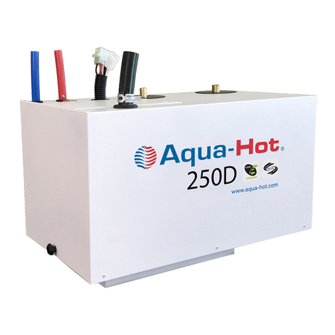
Airxcel
Airxcel Aqua-Hot 200 Series installation manual

Chromalox
Chromalox HSK-PC installation instructions
Swep
Swep Minex M10 installation manual
aldes
aldes VEX400 Installation and maintenance manual

Daikin
Daikin VRV IV+ Installer and user reference guide
