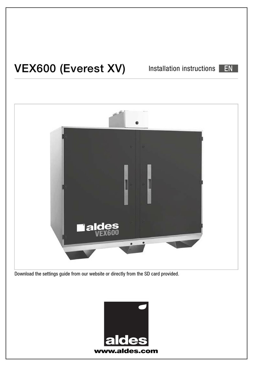
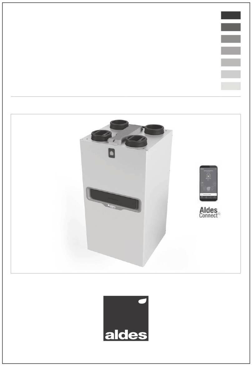
aldes VEX400 Manual

www.aldes.com
VEX400
Installation and
maintenance manual
EN

2
CONTENTS
1. RECOMMENDATIONS AND SAFETY INSTRUCTIONS ..........................................................................................4
1.1. Personal safety...................................................................................................................................................4
1.2. Precautions for installation and maintenance ................................................................................................4
2. INSTALLATION ..........................................................................................................................................................5
2.1. General information ...........................................................................................................................................5
2.2. Transport on site ................................................................................................................................................5
2.3. Parts supplied with the unit ..............................................................................................................................6
2.3.1. Water coil option.................................................................................................................................................... 6
2.4. Installation of the unit........................................................................................................................................6
2.4.1. General information............................................................................................................................................... 6
2.4.2. Exterior version...................................................................................................................................................... 6
2.5. Airflow direction ................................................................................................................................................7
2.5.1. Right-hand version ................................................................................................................................................ 7
2.5.2. Left-hand version................................................................................................................................................... 7
2.6. Installation of the temperature probe (air supply sensor)..............................................................................7
2.7. Fitting of options/accessories..........................................................................................................................8
2.7.1. Installation of adapters.................................................................................................................................9
2.7.2. Installation of hoods .............................................................................................................................................. 9
2.7.3. Installation of air inlet/outlet damper................................................................................................................... 9
2.7.4. Connection of standard exible sleeves ...........................................................................................................11
2.7.5. Connection of the CO2 sensor ..........................................................................................................................11
2.7.6. Internal water coil option ....................................................................................................................................12
2.7.7. Constant pressure option ...................................................................................................................................13
2.8. Hydraulic connection.......................................................................................................................................14
2.8.1. Connecting condensates general ..............................................................................................................14
2.8.2. Connecting condensates heat exchanger .................................................................................................14
2.9. Connection to the electrical supply ...............................................................................................................15
2.9.1. Control - Power principle...........................................................................................................................15
2.9.2. Electrical cable connections - power or control .......................................................................................16
2.9.3. General power connection (single-phase) of the unit ................................................................................16
2.9.4. Defrosting coil or heating coil power connection (optional).......................................................................17
2.10. Servicing filters ..............................................................................................................................................17
2.10.1. Filter replacement following timer............................................................................................................17
2.10.2. Filter replacement following clogging indicator .......................................................................................17
2.11. Remote control communication...................................................................................................................18
2.11.1. Remote control use..................................................................................................................................18

3
3. DIMENSIONS...........................................................................................................................................................19
3.1. Unit dimensions ...............................................................................................................................................19
3.2. Outside accessory dimensions.......................................................................................................................19
3.2.1. Roof cowl ...................................................................................................................................................19
3.2.2. Rain hoods.................................................................................................................................................20
3.2.3. Shut-off dampers.......................................................................................................................................20
3.2.4. Adapter drawings.......................................................................................................................................20
3.2.5. Flexible sleeve drawings ............................................................................................................................21
4. CONTROL OPTIONS...............................................................................................................................................22

4
Read the manual carefully before starting to install the equipment and keep it in good condition near the equipment throughout its lifetime.
1.1. Personal safety
• This device may be used by children at least eight years old and by persons with impaired physical, sensory or mental capacities, or with no
experience or previous knowledge, on the condition that they are correctly supervised or that they have received instructions on the safe operation
of the device and if the potential risks have been understood.
• Children should not be permitted to play with the device. User cleaning and servicing tasks should not be done by children without suitable
supervision.
1.2. Precautions for installation and maintenance
• Installing a VEX unit can be risky due to live components or moving mechanical parts. This equipment must be installed, commissioned and repaired
by qualied, trained personnel, in compliance with the standards in force and best practices.
• Any servicing or maintenance operation that necessitates opening the access doors or removing components from the unit must be carried out by
a qualied professional without fail.
• Electrical connections must be made by a qualied professional according to the rules of French standard NF C 15-100.
• In particular, a circuit breaker device with an opening distance of at least 3 mm on each pole, as well as a protective relay with a suitable current rating,
must be installed in the xed ducts (circuit breaker). The copper conductor sections are dened in Sections 2.9.3 and 2.9.4 of the installation manual.
• The product's power supplies must be switched off before any maintenance or cleaning operation.
• Make sure that the unit cannot start running accidentally.
• If one of the power supply cords is damaged, it must be replaced by the professional who installed the product or similarly qualied persons to avoid
danger.
• Overheating of the motor will reduce its modulation in linear fashion. When it exceeds its maximum permitted inside temperature, the controller stops
the motor and restarts automatically after cooling. Should the motor fail (signal fault in the motor's built-in circuit, phase breakdown, motor blocked,
short circuit at the earth or internal short circuit, intermediate and network under-voltage or over-voltage, peak current fault), an alarm triggers the
stopping of the unit. Switch off the power supply (circuit breaker on electrical switchboard), check that nothing is hindering the operation of the unit
(for example, blocking, rubbing, fouling of the wheel, abnormal noise, etc.).
• If the problem persists, contact your installer or vendor.
• Only use genuine replacement parts supplied by the manufacturer.
• For units tted with an electrical heating coil: where there are multiple failures of the electrical coil control and if the air supply compartment overheats
(ambient temperature > 80°C), a thermostat with automatic reset will trigger the stopping of the electrical coil. The electrical coil is tted, moreover,
with a thermostat with manual reset activating at 120°C located in a thimble, between the resistors.
• The equipment must not be modied in any way to avoid invalidating the warranty.
• Service the equipment regularly to ensure its smooth operation.
1. RECOMMENDATIONS AND SAFETY
INSTRUCTIONS

5
2.1. General information
Caution: the purpose of this document is to guide the installation of the unit. For a fully-compliant installation, refer to the legislation in force in the
country of installation (e.g. NF DTU 68-3 part 1.1.4).
• Access
Connection box
Access electrical board recessed Torx screwdriver T30
Unit power supply: Single-phase 230 VAC + E
VEX410 coil power supply (as per options): Three-phase 400 VAC + N + E
VEX420 to VEX440 coil power supply (as per options):
Three-phase 400 VAC + N + E
Aeraulic
component
access with
Torx screws
M6
Aeraulic component
access with Torx T30
screws M6
The unit's rating plate is duplicated. One plate is located on the back of the quick access hatch and another on the side panel.
The unit is packed in plastic lm, protected with cardboard corners. All accessories ordered with the unit are supplied untted. See Section 0 for the
tting of accessories.
Caution: do not drill into the panel between the two access doors or the oors as they carry cable networks!
2.2. Transport on site
The unit is mounted on cross bars. When using a forklift truck for transport, make sure that the forks are long enough to support all the side rails. Make
sure you do not damage the cross bars when inserting the forks under the unit (plan for a gap of at least 200 mm).
Side rails
Cross bars
Fork spreading min. 350 mm
2. INSTALLATION

6
Handling with slings: use handling bars placed in the cross bars. The rigidity at the sag of bars must be adapted to the weight of the crate. Place the
sling buckles around the handling bars and place spreaders above the unit to avoid damaging the structure. See diagram below.
mounted. See Section 0 for the tting of accessories.
Caution: if a water coil is tted, condensates are discharged in the air intake leg! Make sure the hose is not damaged when inserting the bars.
Space required for servicing: it must be possible to open the two side doors at least 90° so that lters can be replaced.
Slings
Four spreaders
Handling bars
2.3. Parts supplied with the unit
A box is placed in the unit containing a water trap with diaphragm to evacuate condensates from the heat exchanger. Depending on the options
chosen, a 3-way valve and a servomotor and a water trap with diaphragm for condensate evacuation from cold coils are all supplied. Depending on the
options chosen, probes, transparent tubes and pressure taps are pre-connected, on stand-by in the side rail air supply side.
All the notices for the use of the unit are behind the new air lter access door. An SD board with USB adapter, containing the software setting and
conguration, is provided in one of the pockets.
A water trap with diaphragm is placed in the box and must be installed after the heat exchanger condensate evacuation hose. See Section 2.8.1.
An air intake probe is connected to the control board, placed on stand-by in the side rail air intake side. See Section 2.6 for the installation.
2.3.1. Water coil option
2.4. Installation of the unit
2.4.1. General information
Mount the unit's legs on a at, stable surface (at ground for condensates).
It is advisable to install an anti-vibration device between the unit's legs and the frame (e.g. studs or carpet) and between the connections and the
aeraulic ductwork (e.g. exible sleeve).
When installing the unit and connecting ducts and electric cables, make sure not to obstruct the access points so that the internal functional
components can be extracted easily and the unit can be connected electrically.
700 mm 700 mm

7
2.4.2. Exterior version
The VEX400 units are protected against spraying water IP24 excluding connections. Units intended for outside use are tted with a roof. To protect the
internal compartments of the unit from rain, a rain hood (sold as option) must be installed on the air inlets and outlets if they have no duct tted. We
also recommend installing, in outside version, shut-off dampers on the air inlet and outlet openings in order to isolate the unit.
Caution: A roof installation must comply with the DTU 43.1, Chap. 5.4. The unit is larger with the hood and the roof! See Section 2.7.2 for the hood
installation and Section 3 for the dimensions.
2.5. Airflow direction
There is a right-hand and a left-hand version
2.5.1. Right-hand version
Fresh air
Discharge
Extraction
Air supply
Fresh airow towards the right
2.5.2. Left-hand version
Fresh air
Discharge
Extraction
Air supply
Fresh airow towards the left
2.6. Installation of the temperature probe (air supply sensor)
The air supply temperature probe is supplied connected to the electronic board, in stand-by in the side rail air intake side. It must be positioned in the
air supply duct. The probe is held along a metal rod passing through a cable gland PG 9, which is itself xed to a metal bracket, ensuring that the duct
is leaktight. Two self-tapping screws are delivered with the unit to x this plate.
Sonde Temp. Soufflage /
Supply Temp. Sensor

8
See the diagram below for the position of the air supply probe in a right-hand machine version (fresh air ow directed towards the right):
Air supply probe position
Caution: When the system has a hot (water or electric), cold or changeover coil, the probe must be positioned at least 1.5 metres after these
heating components - to guarantee a uniform temperature in the section.
Drill a hole between Ø21 mm and Ø30 mm in the duct so that the probe and gland can be threaded through. Apply a bead of mastic to the metal plate
around the gland to make the duct leaktight. Insert the two self-tapping screws to x the plate to the duct.
2.7. Fitting of options/accessories
The two side panels are tted with M8 inserts at each corner of the opening frame to accommodate the external accessories (adapters - hoods).
Dampers Adapters
Rain hood
Damper

9
2.7.1. Installation of adapters
The adapters are supplied with four screws M8 to install them on the unit. Glue the seal 10x20, supplied with the unit, to the connection between the
inserts M8 and the opening to keep the unit leaktight (air and water) between the adapter and the unit. Then screw each adapter into the frame inserts.
Circular ducts must be tted with a seal to connect them. See the diameters per machine in Section 3.3.
Isolate the ducts and shape parts in accordance with the standards and regulations in force.
2.7.2. Installation of hoods
The hoods are supplied with screws M8 and a self-adhesive seal of section 10/20 mm in EPDM. Glue the seal to the hood ange to keep the structure
leaktight.
The hoods protect the unit from water ingress. They can be xed to the opening frame, a damper or a rectangular duct.
Caution: To avoid recirculation of discharged air towards fresh air, plan for at least 4 mm between the air inlet and outlet (see DTU 68-3 part 1-1-4
for residential buildings). For service buildings, the RSDT makes it mandatory for "the extract air from premises must be discharged at least eight
metres from any window or fresh air intake".
See Section 3.2.2 for hood dimensions.
2.7.3 Installation of air inlet/outlet damper
2.7.3.1. Fixing of dampers
The dampers are supplied with pre-cables, tted servomotors, an "RG" connecting cable (be there one or two dampers), a junction box, self-tapping
screws and screws M8. Make the structure leaktight and screw each damper into the inserts on the opening frame.
2.7.3.2. Electrical connection of air inlet-outlet dampers
Thread the "RG" cable into the side rail through the cable gland provided for this purpose and bring the cable out on the side panel on the side of the
shut-off dampers (fresh air/discharged air side). Fix the junction box to this side panel, between the two dampers, with self-tapping screws. Thread the
"RG" cable through one of the glands in the junction box.

10
The junction box is used to connect the damper's servomotor cable to the "RG" connecting cable. When there are two dampers (air inlet and outlet),
the two servomotor cables are connected in parallel. Wire the equipment (see diagram below) according to the conguration - one or two dampers.
1 fresh air or discharged
air damper only
Black strand
Red strand
Three-way connector
Three-way connector
Junction box
Towards terminal block
Towards damper
Two fresh air or discharged
air dampers in parallel
Black strand
Red strand
Three-way connector
Three-way connector
Junction box
Towards terminal block
Towards damper
Damper servomotor cable
RG cable
Damper servomotor cable
RG cable
Once this wiring has been completed, shut-off damper side, wire the equipment electronic board side.
To ensure that the junction box is leaktight, thread the "RG" cable through one of the right-hand cable glands PG9, located under the junction box.
Connect the two "red and black" strands in the "RG" cable to the two terminals of connector "1". See diagram below:
Caution: the strand must be connected to the +24V and the strand to the earth.
Pas de neutre
sur la VEX410
Pas de neutre
sur la VEX410
No neutral on VEX410
See Section 3.2.3 for shut-off damper dimensions.

11
2.7.4. Connection of standard flexible sleeves
The exible sleeve is a layer of glass bre, re class M0, supplied with four screws M8, eight washers and four nuts. This
sleeve can be xed to a damper or directly to the opening frames. See Section 3.4. for sleeve dimensions.
Screw each exible sleeve into the inserts on the opening frame or to the shut-off dampers, assembling washer, screw
and nut at each assembly corner. Isolate the ducts in accordance with the standards and regulations in force.
The kit includes two cables RJ12, a split RJ12 (two female inlets > one female outlet) and a module "OJ Air" LON". The
assembly is pre-wired and factory-tted at the connection terminal block.
Connect the cable RJ12 labelled "R11", on stand-by in the side rail, to one of the two female sockets RJ12 available on the LON module. The LonWorks
network cable must be connected to the module "OJ Air2 LON" via the two-point PTR connector on the module.
2.7.5. Connection of the CO2sensor
The "SENS" CO2 probe, ref. 11017090, is supplied as a an accessory. It must be connected to terminals 3 and 4 on the board as per the drawing below:
Pas de neutre
sur la VEX410
Pas de neutre
sur la VEX410
No neutral on VEX410
A
1
2
3
4
5
6
7
8
0/10V
Analog voltage imput
SENS CO2probe terminal board
-
+
BOOST
Hot/Cold
Fire
B
+ 24 V+
GND
GND
ϑ
T
CO2

12
2.7.6. Internal water coil option
The internal water coils are supplied with a motorised, pre-wired 3-way valve, a "Water Bat" control cable and a "TAG" temperature probe (to measure
the temperature of the uid circulating in the coil and prevent the water circuit from potentially icing up).
The "Water Bat"cable and the temperature probe are connected to one side on the electronic board. On the other side, they are on stand-by in the
side rail, air supply side, ready to be connected by the tter.
Connect the 3-way valve and the coil collectors hydraulically.
Connect the male connector of the "Water Bat" cable to the female connector on the servomotor.
Caution: the electrical connections on outside equipment or equipment located in a moist environment must be watertight. It is recommended to
protect the connections between the servomotor cable and the "Water Bat" cable by at least class IPX5 protection.
Position the temperature probe in the 3-way valve on the internal coil, reverse water ow side, with a plastic collar. To increase the accuracy of the uid
temperature measurement, isolate the probe and the 3-way valve (see wiring diagram below)
"Water Bat" cable
Male
four-point
connector
Female
four-point
connector
Servomotor cable
3-way valve
Towards CTA
connection box
Towards the 3-way valve
Servomotor
3-way valve
coil water reverse
3-way valve servomotor connection diagram
3-way valve
Probe T° on 3-way valve
Collar clips
T° probe
Insulation
TAG
Probe connection diagram on internal water
coil water reverse
Coil water return
Coil water inlet
AAB
B
WATER COIL

13
2.7.7. Constant pressure option
In constant pressure option, the unit is going to maintain a constant pressure in the network (at beginning of network - unit outlet air supply side
and at end of network - unit inlet extraction side). To achieve this, the unit must measure the differential static pressure between the network airow
and the ambient air in each ow. These two pressure sensors are located in the electrical box. On each sensor, one of the two pressure taps is free
(measurement of the static atmospheric pressure) and the other is connected to a transparent capillary tube, on stand-by in the side rail air supply side.
These two capillary tubes are equipped with pressure taps and identied by a "pression insufation/supply pressure" label to measure the air supply
pressure and "pression extraction/extract pressure" to measure the extraction pressure.
Please the pressure tap of the hose marked "supply pressure" on the air supply duct.
Pression Insufflation /
Supply Pressure
Please the pressure tap of the hose marked "extract pressure" on the extraction duct.
Pression Extraction /
Extract Pressure
Air supply pressure tap position
Extraction pressure tap position
Caution: to obtain more accurate measurements, the pressure must be measured where there is the least risk of turbulence, i.e. on a straight
section of the duct. The minimum distance to be respected from any disturbance is at least twice the diagonal of a rectangular section and at least
twice the diameter of a circular section.

14
2.8. Hydraulic connection
2.8.1. Connecting condensates general
All condensate evacuations must be connected without fail to a water trap (plate heat exchanger and cold coil optional). These water traps are delivered
with every unit, in a box placed in the unit. The water traps with diaphragm are used to combat the negative pressure prevailing in the equipment, so
that condensates can be evacuated or to prevent air leaking from the u
Water trap with diaphragm
Condensate
evacuation direction
nit.
Watch out for the risk of frost in winter, plan to insulate the water trap and the evacuation manifold if they are in an unheated atmosphere.
2.8.2. Connecting condensates heat exchanger
Our condensate trays are equipped with an evacuation pipe crossing the oor. This comprises a plughole and a PVC hose Ø32. The water trap with
diaphragm is delivered in the box of separate parts. Connect the water trap with diaphragm to the evacuation hose.
Caution: Respect the condensate evacuation direction indicated by an arrow on the connector.
Plughole
PVC hose Ø 32 mm
Water trap with diaphragm
Ø 32 mm female

15
2.9. Connection to the electrical supply
Caution: electrical connections must be made by a qualied electrician, wearing the appropriate Personal Protection Equipment. Never work on a
live unit. The electrical connection will be in compliance with NF-C 15-100. Each supply network must be protected by an omnipolar circuit breaker
with an opening distance of 3 mm per contact. For a single-phase supply, used a leak current differential circuit breaker type A. For a three-phase
supply use a leak current differential circuit breaker type B. We recommended a sensitivity of 300 mA for the differential for both these types of
supply. The amperage draw recommended for each circuit breaker, according to the sizes of units, is dened in Sections 2.9.3 and 2.9.4. Maximum
recommended ambient temperature < 45°C. Do not forget to connect the earth.
2.9.1. Control - Power principle
Every unit has an electrical connection box on the front panel. This box gives access to the electrical power and control components (disconnect
switches, cut-off supply, electronic control board, etc.). The unit has a general supply electrical circuit and, depending on the options, an electrical coil
circuit (defrosting and heating).
The electrical components are accessed via a hatch equipped with hexagonal recessed head screws M6.
Electrical connection box
4x Torx t30
screws M6
Unit power supply switch:
Single-phase 230 VAC + E
Heating coil power supply:
VEX410 : Three-phase VAC + E
VEX420 to 440: Three-phase VAC + N + E
Defrosting coil power supply: VEX410 :
Three-phase VAC + E
VEX420 to 440: Three-phase VAC + N + E
No. Description
APower supply 230 VAC> 24 Dc
BControl board
CPressure sensor:
constant airow or constant pressure option
DGeneral disconnect switch
EDefrosting coil disconnect switch
FPost-heating coil disconnect switch
A
B
C
D
E
HGF
A
B
CC
FED

16
2.9.2. Electrical cable connections - power or control
Loosen the four recessed head screws M6 Torx t30 on the connection box access hatch. Thread the power cables through the cable glands to make
the equipment leaktight.
The power cable conductors that are rigid or tted with end pieces are screwed in the xed body of each switch.
2.9.3. General power connection (single-phase) of the unit
Thread the power cable through the left-hand cable gland and connect the general power cable to the corresponding switch, according to the wiring
diagram below:
Pas de neutre
sur la VEX410
Pas de neutre
sur la VEX410
No neutral on VEX410

17
2.9.4. Defrosting coil or heating coil power connection (optional)
Thread the coil power cable through one of the cable glands in the middle and connect the coil power cable to the corresponding switch to the wiring
diagram below:
Pas de neutre
sur la VEX410
Pas de neutre
sur la VEX410
No neutral on VEX410
Caution: Each coil is run by a static relay, which is likely to generate interference. Using mains lters can prove necessary when the user must meet
the EMC requirements (EN/IEC standard).
2.10. Servicing filters
Caution: Filters must be serviced by a person with electrical accreditation, with the machine switched off (live LV conductor).
Filters can be replaced according to a basic available timer or a clogging indicator sold as an option (lter fouling).
2.10.1. Filter replacement following timer
This timer, according to the factory setting, will trigger after three months (the user can congure this value, see conguration guide).
We advise changing the lters according to the use and environmental conditions every:
- Filters G4: ISO coarse 60%): Three months
- Filters M5: ISO ePM10 50%): Three months
- Filters F7 Plan only (ISO ePM1 60%): Three months
- G4+ F7 lters: Three months for G4, six months for F7
2.10.2. Filter replacement following clogging indicator
This indicator is produced by a pressure sensor (sold as an option) which, depending on the factory setting, will trigger at the following recommended
nal head losses:
Filters G4 (ISO coarse 60%): 150 Pa ECO – 200 Pa MAX
Filters M5 (ISO ePM10 50%): 200 Pa ECO – 300 Pa MAX
Filters F7 Plan (ISO ePM1 60%): 200 Pa ECO – 300 Pa MAX
G4+ F7 combination: 350 Pa ECO – 500 Pa MAX

18
2.11. Remote control communication
2.11.1. Filter replacement following timer
The remote control is tted with a display, a conrm button, two navigation buttons (+ or -) and eight indication LED.
Please refer to the conguration guide to congure the machine when installing it or for any technical intervention.

19
3. DIMENSIONS
3.1. Unit dimensions
Model A (mm) B (mm) C (mm) H (mm)
"Connection
between centres
fixing
F x G (mm)"
Weight (kg)
VEX410 1505 578 628 904 440 x 240 160
VEX420 1822 578 628 1157 440 x 340 205
VEX430 1825 910 954 1157 740 x 340 291
VEX440 2166 910 954 1468 640 x 440 366
3.2. Outside accessory dimensions
3.2.1. Roof cowl
A
B
A
H
F
G
C
D
E
Fresh air Extraction
Discharge Air supply

20
3.2.2. Rain hoods
E
D
B
A
C
F
A (mm) B (mm) C (mm) D (mm) E (mm) F (°)
VEX 410 255 452 240 440 360 35
VEX 420 355 452 340 440 360 25
VEX 430 355 752 340 740 360 25
VEX 440 455 652 440 640 405 25
3.2.3. Shut-off dampers
F85 130
4x Ø 10
D
B
C
A
E
A (mm) B (mm) C (mm) D (mm) E (mm) F (mm)
VEX 410 270 470 240 440 210 410
VEX 420 370 470 340 440 310 410
VEX 430 370 770 340 740 310 710
VEX 440 470 670 440 640 410 610
3.2.4. Adapter drawings
D
B
C
A
Ø E
A (mm) B (mm) C (mm) D (mm) ØE (mm)
VEX 410 308 478 240 440 250
VEX 420 418 478 340 440 315
VEX 430 418 778 340 740 355
VEX 440 518 618 440 640 450
Table of contents
Other aldes Heating System manuals

aldes
aldes EXHAUSTO InspirAIR Top User manual

aldes
aldes InspirAIR Commercial Series User manual

aldes
aldes VEX600 User manual

aldes
aldes Dee Fly Cube 550+ User manual

aldes
aldes EVEREST XV User manual

aldes
aldes H650 User manual

aldes
aldes InspirAIR Top 300 Classic User manual

aldes
aldes VEX500 User manual
Popular Heating System manuals by other brands

HDG
HDG Compact 25 Operation manual

Lennox
Lennox Lennox CompleteHeatTM COMBINATION HEATING... User's information manual

Viessmann
Viessmann VITODENS operating instructions

Scholl
Scholl CP 330 Instructions for use

Schako
Schako DISA-W Installation, Mounting and Maintenance

Lava
Lava DESK 120 Installation and usage instructions