EC POWER XRGI 6 Installation and operation manual

VERSION 1.0 201901DOC1075-01
COMMISSIONING INSTRUCTION


XRGI® COMMISSIONING INSTRUCTION VERSION 1.0 2019
3
CONTENT
1. SYSTEM AND DOCUMENTATION INFORMATION 3
1.1 VALIDITY OF THE INSTRUCTION 3
1.2 RATING PLATE 3
2. SAFETY INSTRUCTIONS 4
2.1 INFORMATION, SAFETY AND WARNING SYMBOLS 4
2.2 INTENDED USE 4
2.3 GENERAL SAFETY INFORMATION 5
2.3.1 HANDLING COOLANT AND ENGINE OIL 6
2.3.2 ACTIONS WITH SMELL OF GAS IN BUILDINGS 6
2.3.3 ACTIONS WITH FIRE OR INGRESS OF WATER 7
2.3.4 ACTIONS WITH SMELL OF EXHAUST GAS IN BUILDINGS 7
2.3.5 FROST PROTECTION 7
2.3.6 CONTACT HAZARD 7
2.3.7 EXPLOSIVE AND EASILY FLAMMABLE MATERIALS 8
2.3.8 COMBUSTION AIR SUPPLY 8
2.3.9 MODIFICATIONS TO THE XRGI® SYSTEM COMPONENTS 8
2.3.10 FILLING AND TOPUP LIQUID 9
2.3.11 PROPERTY DAMAGE CAUSED BY IMPROPER USE OF AND/OR UNSUITABLE TOOLS 9
2.3.12 MODIFICATIONS IN THE VICINITY OF THE XRGI® SYSTEM 9
2.3.13 OPERATION WITH LIQUID GAS 9
2.3.14 WORKING ON THE ELECTRICAL SYSTEM 10
2.3.15 SAFETY EQUIPMENT ON THE XRGI® SYSTEM 10
2.3.16 SAFETY AND WARNING LABELS ON THE XRGI® SYSTEM 11
2.4 WARRANTY INFORMATION 11
2.5 REGULATIONS, STANDARDS AND LAWS 11
3. COMMISSIONING XRGI® 6 13
3.1 INSTALLATION CHECK 13
3.2 COMMISSIONING 13
3.2.1 BLEEDING 14
3.2.2 ELECTRONICS COMPARTMENT 15
3.2.3 PARAMETER SETTING 16
3.2.4 MAINTENANCE 18
3.2.5 IO STATUS 18
3.2.6 PRODUCTION 18
3.2.7 FLUE GAS MEASUREMENT 19
3.2.8 MODEM CALL 20
3.2.9 COMPLETION 20
4. COMMISSIONING XRGI® 9 21
4.1 INSTALLATION CHECK 21
4.2 COMMISSIONING 21
4.2.1 BLEEDING 22
4.2.2 ELECTRONICS COMPARTMENT 23
4.2.3 PARAMETER SETTING 24
4.2.4 MAINTENANCE 26
4.2.5 IO STATUS 26
4.2.6 PRODUCTION 26
4.2.7 FLUE GAS MEASUREMENT 27
4.2.8 MODEM CALL 28
4.2.9 COMPLETION 28

XRGI® COMMISSIONING INSTRUCTIONVERSION 1.0 2019
2
5. COMMISSIONING XRGI® 15 29
5.1 INSTALLATION CHECK 29
5.2 COMMISSIONING 29
5.2.1 BLEEDING 30
5.2.2 ELECTRONICS COMPARTMENT 31
5.2.3 PARAMETER SETTING 32
5.2.4 MAINTENANCE 34
5.2.5 IO STATUS 34
5.2.6 GAS QUALITY 34
5.2.7 PRODUCTION 35
5.2.8 GAS & AIR MIXTURE ADJUSTMENT 35
5.2.9 MODEM CALL 36
5.2.10 COMPLETION 36
6. COMMISSIONING XRGI® 20 37
6.1 INSTALLATION CHECK 37
6.2 COMMISSIONING 37
6.2.1 BLEEDING 38
6.2.2 ELECTRONICS COMPARTMENT 39
6.2.3 PARAMETER SETTING 40
6.2.4 MAINTENANCE 42
6.2.5 IO STATUS 42
6.2.6 PRODUCTION 42
6.2.7 FLUE GAS MEASUREMENT 43
6.2.8 MODEM CALL 44
6.2.9 COMPLETION 44
Subject to technical changes, design modications and errors. All pictures shown are for illustrative purposes only.
XRGI® COMMISSIONING INSTRUCTION VERSION 1.0 2019
3
1. SYSTEM AND DOCUMENTATION INFORMATION
This commissioning instruction provides important information on commissioning the XRGI® system. Before commissioning the
XRGI® system, please read this commissioning instructions carefully, especially the safety instructions. If you have any problems un-
derstanding, contact your EC POWER dealer before starting work.
1.1 VALIDITY OF THE INSTRUCTION
This commissioning instruction only applies to XRGI® systems with the following item numbers:
Type Item number
XRGI® 6 X060001
XRGI® 9 X090001
XRGI® 15 X150001
XRGI® 20 X200001
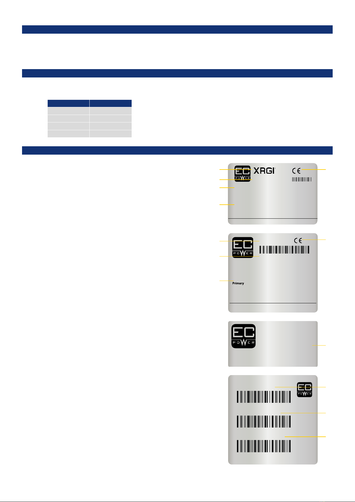
1.2 RATING PLATE
POWER UNIT
The rating plate is located on the back of the Power Unit.
LEGEND
1 Power Unit serial no.
2 Type description of the XRGI® system
3 Description of the type approval
4 Technical data of the Power Unit
5 CE marking
Q-HEAT DISTRIBUTOR
The rating plate is located on the inside of the Q-Heat Distributor below
the electronics box.
LEGEND
1 Q-Heat Distributor serial no.
2 Type description of the Q-Heat Distributor
3 Technical data of the Q-Heat Distributor
4 CE marking
iQ-CONTROL PANEL
The iQ-Control Panel has two rating plates. These are located on the inside
of the iQ-Control Panel door and on the left side of the iQ-Control Panel,
below the main switch disconnector.
LEGEND
1 iQ-Control Panel serial no.
2 Technical data of the iQ-Control Panel
3 Type description of the iQ-Control Panel
4 XRGI®-ID of the XRGI® system
0845-16
Serial No. 0414000371
Co-generation for domestic heating and electric power supply
Flue Code B23P CE 0845BS-0031
Category II2H3+ Qn =
3 x 400 V, 50Hz - 15 kW Fuse 50 A gL/gG
EC POWER A/S Samsøvej 25 DK-8382 Hinnerup +45 87 43 41 00 www.ecpower.eu
2H
3+
3+
G20 - 20
G30 - 28-30
G31 - 30
l/min
l/min
l/min
mbar
mbar
mbar
44,4 - 82,5
13,4 - 24,9
17,4 - 32,3
V =
V =
V =
26,5 - 49,5 kW
15
1
2
3
4
5
Q-80
Serial no. 2516010237
EC POWER A/S ●Samsøvej 25 ●DK-8382 Hinnerup ● +45 87 43 41 00 ●www.ecpower.eu
Heat distribution for domestic co-generation system
Circuit Pressure Temp. Flow rate
< 1 Bar < 95
o
C 2-5 m
3
/h
Secondary < 6 Bar < 85
o
C 0-5 m
3
/h
230 V, 370 W
4
1
2
3
EC POWER A/S
SAMSØVEJ 25
DK-8382 HINNERUP
TEL. +45 87 43 41 00
WWW.ECPOWER.DK
SERIAL NO : 33 15 06 06 28
Ike : 10kA i 0,2 Sec
ENCLOSURE : 54 IP
SUPPLY VOLTAGE : 3 x 400 VAC+N+PE
CONTROL VOLTAGE : 24 VDC
FREQUENCY : 50 Hz
PANEL LOAD : 43 A
GROUNDING SYSTEM : TN-S / TT
2
iQ15 - 17ELD1007
XRGI-ID 1534894421
Serial No. 3317050637
EC POWER A/S - Samsøvej 25, 8382 Hinnerup - www.ecpower.eu
3
4
1

XRGI® COMMISSIONING INSTRUCTIONVERSION 1.0 2019
4
2. SAFETY INSTRUCTIONS
2.1 INFORMATION, SAFETY AND WARNING SYMBOLS
Please read the following section carefully and observe the safety instructions. If you are unsure about any matters, or any information
cannot be understood, please contact your EC POWER dealer. The XRGI® system was constructed according to the current applicable
rules and standards for technical equipment and in compliance with recognised, conventional safety measures. To achieve the maxi-
mum possible safety, it is essential that all the safety information contained in this user manual is adhered to and fully implemented. To
avoid any residual hazards and/or risks, it must be ensured that no unauthorised persons (especially children) can come into contact
with the XRGI® system.
During operation of the XRGI® system, observe the general information, safety and warning instructions.
Safety symbols are used in this document to indicate the potential dangers and/or hazards relating to a certain situation.
INFO!
This info symbol refers to important and useful information about the issue.
CAUTION!
This safety symbol refers to a potentially hazardous situation that could lead to minor personal injury. It is also used in instances of
imminent damage to property.
WARNING!
This warning symbol refers to a potentially dangerous situation that could lead to serious personal or fatal injury.
2.2 INTENDED USE
The intended use includes:
■compliance with the applicable operating, installation, commissioning and maintenance instructions of the XRGI® system as well
as other components and components of the XRGI® system
■installation and assembly in accordance with the device and system approval
■compliance with all inspection and maintenance conditions specified in the instructions
The EC POWER XRGI® system is not intended for use in the industrial sector within the meaning of the Machinery Directive.
Any improper use is prohibited!
Improper or not intended use of the XRGI® system can result in danger to life and limb of the user or third parties or damage to the
XRGI® system and other property.
The XRGI® system is a combined heat and power generation system and must be used for this purpose only in single-family and
multi-family houses, small businesses, hotels, restaurants, residential homes, schools, etc. The XRGI® system is intended for:
■heat generation for closed hot water and central heating systems
■the simultaneous generation of electrical energy and its supply to the public power grid
■central hot water heating in private homes and businesses
Any other or further use is considered improper use. The manufacturer/supplier is not liable for resulting damages. The risk is borne
by the user alone.
EC POWER assumes no liability for damages caused by non-compliance with this installation guide.

XRGI® COMMISSIONING INSTRUCTION VERSION 1.0 2019
5
2.3 GENERAL SAFETY INFORMATION
Only a certified, skilled installer who has undergone special training for the XRGI® system through EC POWER may commission the
XRGI® system. During installation and commissioning, the skilled installer must observe the existing rules, regulations and guidelines.
The skilled installer also assumes responsibility for the proper installation and commissioning.
Please observe the following safety instructions for protection against electric shock, injury and fire risks:
■Only use the XRGI® system for its intended use.
■Install the XRGI® system on a stable foundation.
■Before commissioning the XRGI® system, ensure that the on-site mains voltage matches the line voltage specified on the ma-
chine‘s rating plate. Ensure compliance with the mains voltage specified by the manufacturer when using or replacing mains
voltage cables on the XRGI® system. Never handle the mains plug with wet hands.
■Ensure that the power cable is undamaged. Any rough or sharp-edged object has the potential to damage the cable. Replace
damaged cables immediately.
■Only connect the cable when the XRGI® system is switched off.
■Take care to ensure that the supply line or extension cable is not damaged by being run over, crushed, stretched or similar. Protect
cables from heat, oil and sharp edges. Ensure that all cabling has the diameter given in the XRGI® manual and is splash-proof.
Ensure that cables are not in permanent contact with water.
■Always use the manufacturer‘s original accessories and spare parts for the XRGI® system.
■Do not wear any jewellery or clothing that could become caught in the machine‘s moving parts.
■Protect electrical equipment from humidity and rain and never immerse it in water. Do not use in a humid environment or in
areas with high levels of atmospheric humidity.
■Your reaction speed can be adversely affected by the consumption of alcohol, medicines and drugs, and also by illness, fever and
tiredness. Do not use the XRGI® system if this is the case.
■Keep children away from the XRGI® system at all times. Only allow persons who have been trained in the handling of the system
or who have provided evidence of their ability to operate it and who have been expressly authorised to operate the XRGI® system.
Do not allow children or young people to operate the XRGI® system. In addition, persons with limited physical, sensory or mental
capabilities, or lack of experience and/or knowledge, are prohibited from operating the XRGI® system unless they are supervised
or instructed in how to operate the XRGI® system by a person responsible for their safety.
■Never reach into the Power Unit with bare hands or other materials when the machine is running.
■Never use water to clean the XRGI® system. Never use solvents, turpentine, petrol, abrasive cleaning agents or similar. Ensure that
all parts have dried out thoroughly before commissioning the system.
■Only allow qualified skilled personnel authorised by EC POWER to perform repairs on the XRGI® system.
■Only allow trained skilled personnel to remove the housing of the XRGI® system.
■If safety equipment has to be removed to permit work on the XRGI® system, then only switch on the XRGI® system when all the
safety equipment has been refitted and checks have been made that it is working properly.
■Never start up the XRGI® system with faulty safety equipment or with safety equipment removed (turn off the master switch).
Immediately replace or dismantle defective safety equipment.
Lightning protection in buildings
The installation of lightning conductors in buildings containing gas installations and sensitive electronics must comply with the
general conditions, supplementary conditions and the requirements in various sections of the Electrical Specification and is strongly
recommended by EC POWER.
The equipotential bonding (see point 3.3.6) additionally contributes to the comprehensive protection of the XRGI® system against
lightning strikes.
If the safety devices are disabled, bridged, manipulated, damaged or removed, or if the XRGI® system is operated
with defective safety devices, there is a risk of injury.
Safety devices must not be manipulated or disabled.

XRGI® COMMISSIONING INSTRUCTIONVERSION 1.0 2019
6
2.3.2 ACTIONS WITH SMELL OF GAS IN BUILDINGS
A malfunction can cause gas to escape and cause poisoning and explosion hazards. Please proceed as follows in the event of any
smell of gas in buildings:
■Close the gas valve on the XRGI® system connection panel and check that the gas valves on all other equipment are closed! Close
all gas fittings that are still open (pilot lights, gas-cooled fridges, etc.)! Do not operate any electrical switches!
■Do not unplug any electrical equipment!
■Do not operate any electrical bells!
■Do not use matches or cigarette lighters!
■Do not smoke!
■Do not use telephones, cordless telephones or mobile phones within the hazard area!
■Immediately open all doors and windows!
■Immediately extinguish all naked flames!
■Immediately close the gas solenoid valve on the gas meter or the main gas solenoid valve!
■Warn other occupants in the building and leave the building!
■Only turn the lights back on when there is no longer any smell of gas!
■Do not rely solely on your own sense of smell – always ask the opinions of others!
■If you cannot find the cause of the gas smell, even though all the gas valves are closed, immediately contact the gas supply
company. Immediately inform the gas supply company even if there is only a slight smell of gas and you cannot locate/identify
the origin of the smell!
■If you smell gas from areas you cannot access directly, immediately call the police and/or fire service who are authorised to gain
entry; at the same time, notify the gas supply company!
■Do not attempt to repair faults or damage to gas systems yourself! Only allow qualified, skilled personnel to remedy any faults (i.e.,
your gas supplier‘s operatives and installation contractors)!
■Ensure that the area affected is accessible to the emergency services!
PROPERTY
■Use absorbent material to wipe off the oil and dispose of it as hazardous waste. Replace clothing and shoes saturated with oil. Do
not put any oily rags and/or cloths in your pockets.
SKIN
■In case of contact, immediately wash skin with plenty of water for at least 15 minutes while removing contaminated clothing
and shoes. Wash skin thoroughly with soap and water or use recognised skin cleanser. Wash clothing before reuse. Seek medical
advice if symptoms persist.
EYES
■Remove contact lenses. Rinse immediately with plenty of water, also under the eyelids, for at least 15 minutes. Seek medical
advice if symptoms persist.
IN THE EVENT OF CONTACT WITH COOLANT AND ENGINE OIL:
2.3.1 HANDLING COOLANT AND ENGINE OIL
Always wear safety gloves and safety glasses when handling coolant and engine oil!
XRGI® COMMISSIONING INSTRUCTION VERSION 1.0 2019
7
2.3.3 ACTIONS WITH FIRE OR INGRESS OF WATER
2.3.4 ACTIONS WITH SMELL OF EXHAUST GAS IN BUILDINGS
Please proceed as follows in the event of fire or the ingress of water:
■Switch off the all-pole breaker!
■Switch off the master switch on the system!
■Close the shut-off valve on the gas pipe!
■Inform the responsible service department!
■In the event of the outbreak of fire, immediately close the gas shut off valve on the connection panel and the main gas solenoid
valve on the gas pipe, cut off the supply of fresh air to the fire and inform the local fire service!
■In case of flooding (e.g., flooding in the basement), do not step into the water!
■Only use approved fire extinguishers to put out the fire!
■Warn other occupants of the building and leave the building!
Due to a malfunction, exhaust gas can escape and lead to the risk of poisoning.
If you smell exhaust gas in buildings, proceed as follows:
■Shut down the XRGI® system!
■Open windows and doors!
■Notify your heating company!
The monitoring systems are only activated when the system‘s master switch is turned to„I“ and the system has not
been isolated from the power supply.
2.3.5 FROST PROTECTION
2.3.6 CONTACT HAZARD
Ensure that the XRGI® system remains in operation and that the area is appropriately heated if you are absent during periods of frost
and/or the winter months.
Components that can cause injury on contact (hot and/or electrically conductive parts) are concealed behind panels that can only be
removed with keys or tools. Only permit authorised EC POWER specialists to remove these panels.
The door on the iQ-Control Panel is there for your protection and should only be opened by trained electricians. The main switch
disconnecter (red switch) is located on the left-hand side of the iQ-Control Panel. When it is switched on, there is a risk of you getting
an electric shock if touching any of the control components. The iQ-Control Panel contains sensitive electronic components. If they
are not handled professionally, the XRGI® system may be damaged.
The cover on the Power Unit is there for your protection. In particular, be aware of the following when opening the Power Unit:
■The engine gets hot. You risk being burned if you touch it or any of the other components.
■The protective cover conceals parts that start to rotate when the XRGI® system starts up and is running. Touching these parts
while the Power Unit is running can be fatal. Only permit authorised and trained personnel to touch components under the
protective cover when the system is running. Avoid wearing loose-fitting clothing, jewellery and untied long hair when checking
the Power Unit visually, as they could become caught up in rotating parts.
■The generator and many other parts are connected to the power supply system. Touching non-isolated parts can be fatal.
■There is a risk of damage to the hearing of anyone in the vicinity of a running Power Unit with an open cover. Please wear
approved hearing protection when the cover is open.
The installation of an equipotential bonding between the CHP and all metal parts near the XRGI® system, gas pipes, water pipes,
ventilation etc. must comply with applicable regulations and ordinances and is strongly recommended by EC POWER. The equipo-
tential bonding must be calculated and carried out professionally and depends on the type of soil protection used (TN-s, TT, etc.). The
equipotential bonding also contributes to the comprehensive protection of the XRGI® system against lightning strikes.
One option for providing frost protection would be to drain the XRGI® system. It must be ensured that the XRGI® system is completely
drained. Always take the advice of your authorised EC POWER specialist.

XRGI® COMMISSIONING INSTRUCTIONVERSION 1.0 2019
8
SOURCES OF HALOGEN COMPOUNDS
Industrial sources
Chemical cleaners Trichloroethylene, tetrachloroethylene, hydrofluorocarbons
Degreasing baths Perchloroethylene, trichloroethylene, methylene chloride
Printing houses Trichloroethylene
Cooling equipment Methyl chloride, trichlorofluoromethane, dichlorodifluoromethane
Domestic sources
Cleaners and degreasing agents Perchloroethylene, methyl chloroform, trichloroethylene, methylene
chloride, carbon tetrachloride, hydrochloric acid
DIY sources
Solvents and thinners Chlorinated hydrocarbons
Spray cans Hydrofluorocarbons (Frigen)
This list is not an exhaustive list.
The solvents used for cleaning and contained in adhesives and paints are crucial. Chemical cleaning and degreasing baths are
sources of halogen compounds, as are flooring adhesives and other adhesives. Construction varnishes, paints and adhesives have
been produced for many years without halogenated hydrocarbons. Air-borne halogen compounds are often released when thinners
containing chlorinated hydrocarbons or adhesive removers containing chlorinated hydrocarbons are used, as well as new coats of
paint in heating plant rooms. Bleach alkalis and hydrochloric acid, often used for disinfection and for cleaning, can also be the cause
of corrosion. Spray paints or adhesives containing CFCs are rarely used today by professional tradesmen. If the source of halogenated
hydrocarbons cannot be completely eliminated (e.g., hairdressing salons, swimming pools, dry cleaning premises etc.), then the
supply of combustion air has to be solely supplied from an uncontaminated area.
2.3.9 MODIFICATIONS TO THE XRGI® SYSTEM COMPONENTS
Do not modify any system components on the XRGI® system without obtaining written approval from EC POWER in advance.
■Never install an additional cover or enclosure around the unit.
■Be sure to comply with the minimum clearances/assembly clearances required.
2.3.7 EXPLOSIVE AND EASILY FLAMMABLE MATERIALS
Do not use or store any explosive or easily flammable materials (e.g., petrol, paper, paint) in the vicinity of where the XRGI® system is
installed. Do not use any sprays, solvents, cleaning materials that contain chlorine, paints, adhesives etc. in the vicinity of the XRGI®
system. These materials could present an ignition hazard but could also lead to corrosion – even in the exhaust system.
2.3.8 COMBUSTION AIR SUPPLY
Check that the supply of combustion air to the XRGI® system is unimpeded. Do not position any equipment with extraction, such
as fans, tumble driers or dehumidifiers, in the vicinity of the XRGI® system without consulting your authorised EC POWER specialist.
Check with your authorised EC POWER specialist to ensure that there is still a sufficient supply of combustion air to the XRGI® system
before fitting moisture-tight windows. The Power Unit‘s combustion air should not contain any solvents or halogen compounds,
which can cause corrosion and damage when the XRGI® system is operated. Halogen compounds are used in industry, trade and
household products.
Closed air supply inlets can result in incomplete combustion and a build-up of carbon monoxide, with the possibility
of poisoning.

XRGI® COMMISSIONING INSTRUCTION VERSION 1.0 2019
9
2.3.10 FILLING AND TOPUP LIQUID
Deposits and encrustation, as well as scale formation and corrosion, can often lead to problems. It is essential to prevent corrosion as
well as deposits. Variables such as oxygen and carbon dioxide content, pH value and the conductivity (salt content) play a crucial role
in terms of the incidence of corrosion in heating circuits. Use EC POWER Engine Coolant, supplied with every new XRGI® system, to fill
and top up the engine circuit to avoid expensive repairs from corrosion in the pipes of XRGI® systems. Only use the heated EC POWER
Engine Coolant for heating purposes in the closed circuit and do not drain it off for other purposes.
The engine circulation water is filled and topped up from the expansion vessel on the Q-Heat Distributor.
We do not recommend adding chemicals to stabilise the hardness of the water, since limescale could develop into
sludge.
2.3.11 PROPERTY DAMAGE CAUSED BY IMPROPER USE OF AND/OR UNSUITABLE TOOLS
Improper use of and/or unsuitable tools can cause damage (e.g., gas or water leaks).
To tighten or loosen screw connections, always use suitable open-end wrenches (spanner), but not pipe wrenches, extensions, etc.
2.3.12 MODIFICATIONS IN THE VICINITY OF THE XRGI® SYSTEM
Do not carry out modifications to the following equipment:
■The XRGI® system
■Gas, supply air, water and electricity pipes and cables
■The exhaust gas system
■The safety valve and the drain pipe for the heating water
■Structural objects that could affect the operational safety of the XRGI® system
2.3.13 OPERATION WITH LIQUID GAS
Venting the liquid gas tank when installing the XRGI® system:
■Before installing the XRGI® system, make sure that the gas tank is vented. In general, the liquefied gas supplier is responsible for
the proper ventilation of the tank. If the tank is poorly ventilated, ignition problems may occur.
■In this case, first contact the company/person responsible for filling the tank.
Avoid wrong gas type:
■The use of a wrong type of gas leads to ignition and combustion noises as well as to fault shut-downs. Therefore, use only
propane or butane gas according to DIN 51622.
Placement of tank label:
■Place the enclosed tank label (gas quality) so that it is clearly visible on the tank or the bottle cabinet, if possible in the vicinity of
the filler neck.
Installation below ground level:
■When installing in rooms below ground level, observe and comply with the applicable regulations, rules and standards..
The operation of the XRGI® system with LPG can only be operated by its own evaporation pressure from the gas tank.
The pressure depends not only on the ambient temperature but also on the heat that can be supplied to the gas tank to maintain the
pressure in the gas tank. If insufficient heat can be supplied, the pressure drops (e.g. 28 mbar> 8 mbar).
An unstable gas pressure supply is technically very unfavourable for a CHP. To counteract this, the gas supply must be dimensioned by
the appropriate supplier as required with tank placement, pipe sizes, evaporator and gas pressure regulator.
Do not undertake any modications to XRGI® components without previous written approval from EC POWER.

XRGI® COMMISSIONING INSTRUCTIONVERSION 1.0 2019
10
2.3.15 SAFETY EQUIPMENT ON THE XRGI® SYSTEM
If the safety devices are disabled, bridged, manipulated, damaged or removed, or if the XRGI® system is operated
with defective safety devices, there is a risk of injury. Safety devices must not be manipulated or overruled.
The XRGI® system is equipped with a number of safety devices that ensure its safe operation.
Safety devices include::
■Main switch disconnecter
■Sound insulation panels (all casing panels)
Make sure that the warning information labels (stickers) on the XRGI® system are always clearly visible, undamaged and
complete. Replace damaged or dirty warning labels. The information labels are available from EC POWER.
Main switch disconnecter on the iQ-Control Panel Sound insulation cladding on the Power Unit
2.3.14 WORKING ON THE ELECTRICAL SYSTEM
Danger to life when working on electrical and electronic components. Only allow skilled and qualied electricians
to perform work on electrical or electronic components in accordance with current, applicable electrical regulations.

XRGI® COMMISSIONING INSTRUCTION VERSION 1.0 2019
11
2.3.16 SAFETY AND WARNING LABELS ON THE XRGI® SYSTEM
The XRGI® system has a number of safety and warning labels to protect the operator of the XRGI® system.
The safety and warning labels include:
POWER UNIT
CAUTION! HOT SURFACE
This warning label warns of hot surfaces. On hot surfaces there is a risk of burns.
Q-HEAT DISTRIBUTOR
CAUTION! HIGH TEMPERATURE/HOT LIQUID
This warning label warns of high temperature/hot liquid. There is a risk of burns on hot liquids.
iQ-CONTROL PANEL
CAUTION! VOLTAGE
This warning label warns of dangerous electrical voltage. Electrical voltage is dangerous to the human body and may result
in personal injury and property damage.
2.5 REGULATIONS, STANDARDS AND LAWS
Adhere to and comply with the provisions, regulations and guidelines applicable in the individual country when installing the XRGI®
system.
2.4 WARRANTY INFORMATION
Comply with the following requirements to uphold the warranty:
■Install and operate the system professionally and in accordance with the applicable EC POWER instructions.
■Only allow personnel trained and authorised by EC POWER to perform regular servicing on the unit in accordance with the
current servicing instructions.
Warranty exclusions: The guarantee excludes damage over which the manufacturer has no direct or indirect influence, such as
■Faulty planning and installation (e.g., fuel supply, hydraulic/electrical connections, exhaust gas extraction)
■Commissioning, servicing and repairs by persons not authorised by EC POWER
■Natural wear and tear
■Faulty, negligent handling, modifications, repairs
■Use of unsuitable equipment/material, unauthorised lubricants
■Use of heating water that does not meet applicable technical guidelines
■Chemical, electro-chemical and electrical influences
■Use of drinking water that does not comply with the generally recognised technical regulations
■Climatic or other effects outside the specifications given in the XRGI® installation manual (e.g., insufficient ventilation, lightning,
overvoltage, severe weather, fire, etc.)
The current version of the guarantee and warranty stipulations in the EC POWER A/S General Terms and Conditions apply.
RETURN OBLIGATIONS
EC POWER is obliged to take back XRGI® systems after their use. XRGI® systems have to be reused or recycled following their return.
Components that cannot be recycled have to be disposed of in an environmentally friendly manner.

XRGI® COMMISSIONING INSTRUCTIONVERSION 1.0 2019
12

13
XRGI® 6 COMMISSIONING INSTRUCTION VERSION 1.0 2019
3.1 INSTALLATION CHECK
3. COMMISSIONING XRGI® 6
Before commissioning the XRGI® 6 system, retrieve the XRGI® service booklet located
inside the iQ-Control Panel. Then, fill in the system information required and fill out the
commissioning protocol. Confirm the protocol with your signature and stamp.
Start the commissioning with an installation check including:
■Hydraulic solutions
■Installation site
■EC POWER Engine Coolant
■Hydraulic connections
■Gas-site connections
■Flue gas-site connections
■Electrical connections
All relevant steps for the installation check are included in the commissioning protocol
as part of the service booklet.
3.2 COMMISSIONING
After completing and passing the installation check, the XRGI® 6 system is ready for
commissioning.
TOOLS REQUIRED
■Wrench, 8 mm
■Wrench, 11 mm
■Allen key, 2.5 mm
■Allen key, 3 mm
■Allen key, 5 mm
■Flue gas analyser
The XRGI® system may not be commissioned if the installation does not
comply with the installation instructions specied in the XRGI® manual
and thus, does not pass the installation check. Commissioning the XRGI®
system in spite of a failed installation check will result in loss of warranty.
14
XRGI® 6 COMMISSIONING INSTRUCTIONVERSION 1.0 2019
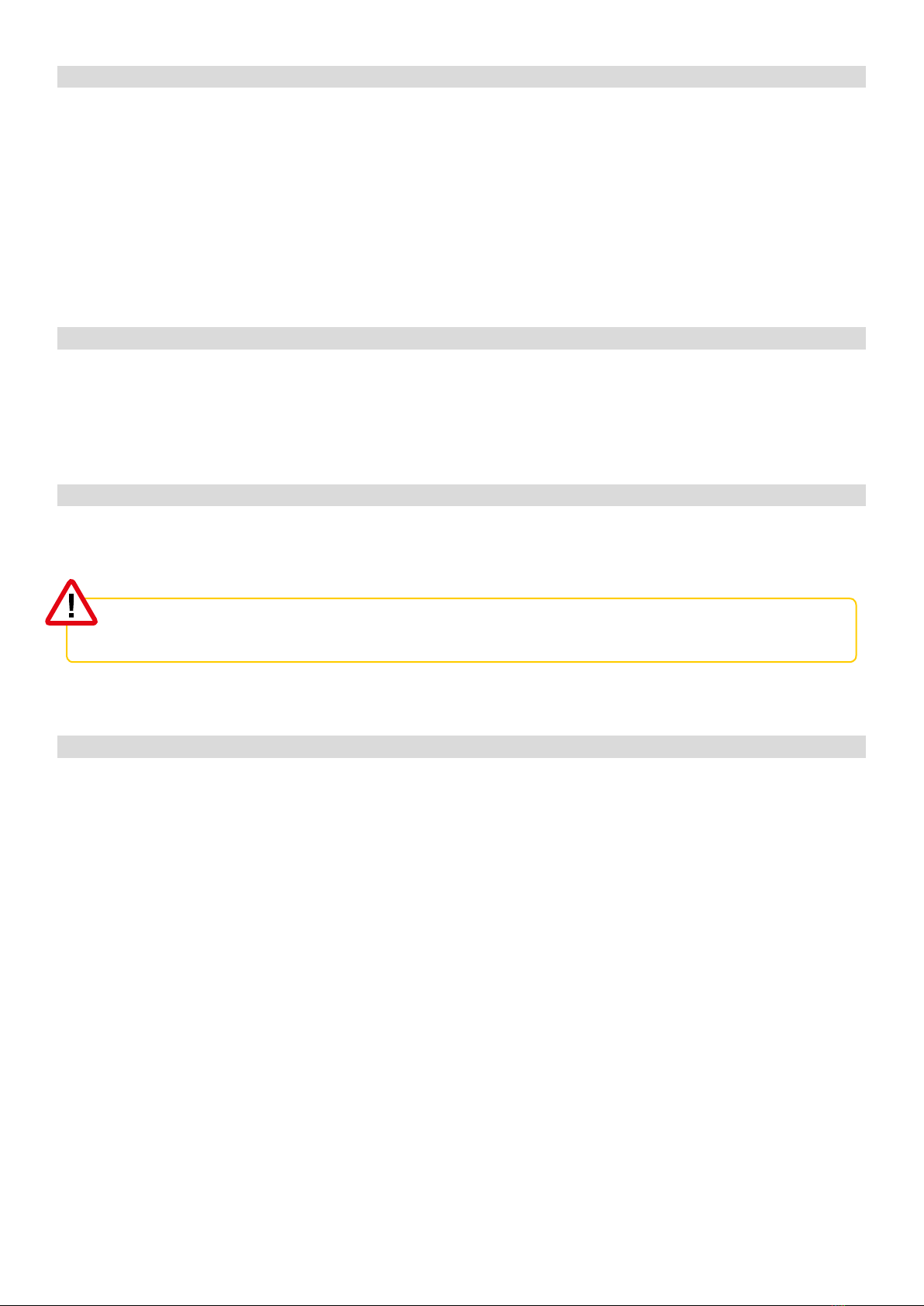
3.2.1 BLEEDING
■Open the Power Unit and remove the Q-Heat Distributor cover.
■Check whether all four valves on the manifold are open on the Q-Heat Distributor.
Open any closed valves.
QHEAT DISTRIBUTOR
■Use a bleed key to bleed the storage circuit on the Q-Heat Distributor. Attach a
hose to the bleed screw to divert any leaking heating water and then use an 11
mm wrench to loosen the bleed screw.
■When only heating water escapes from the bleed screw, tighten the screw.
■Add XRGI® Engine Coolant to the expansion vessel on the Q-Heat Distributor. Add
up to the maximum mark.
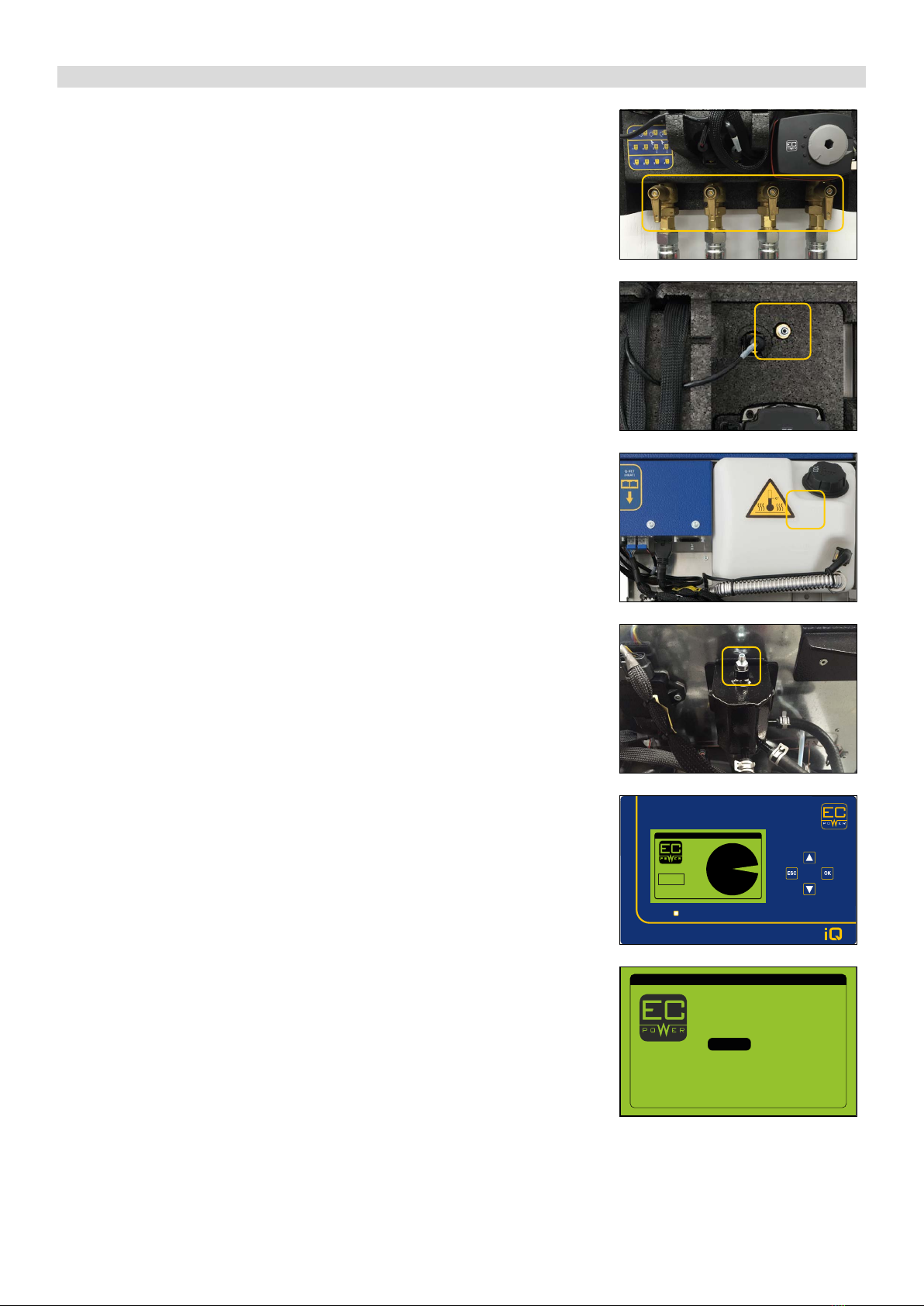
POWER UNIT
■Bleed the engine circuit at the air pot on the Power Unit. Attach a hose to the
bleed screw to divert any leaking XRGI® Engine Coolant and then use an 11 mm
wrench to loosen the bleed screw.
■Bleed until only XRGI® Engine Coolant and no air escapes.
■When only XRGI® Engine Coolant escapes from the bleed screw, tighten the screw
and check if there is still sufficient XRGI® Engine Coolant in the expansion vessel. If
necessary, refill XRGI® Engine Coolant to the maximum mark.
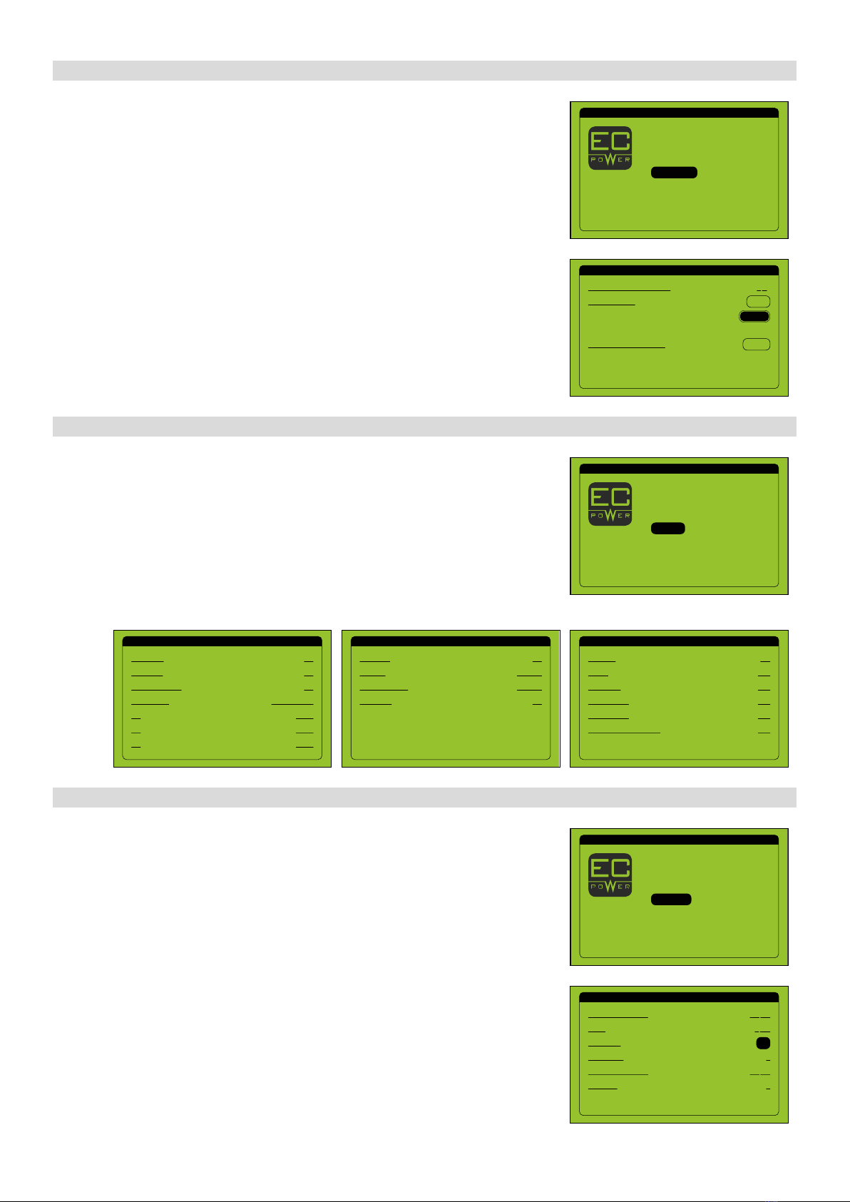
iQCONTROL PANEL
■Press any key on the user interface to activate the display and enter the menu.
■Press any button on the user interface again to enter the main menu.
■Move the cursor to Technician by using the ▲▼buttons and press OK on the
user interface.
1/1
Production: 9.9 kW
Consumption 10.1 kW
98 %
13:10:16
22.05.2019
1234567890
MAIN MENU 1/1
Statistics
Start/Stop
Heat pumps
Modem call
Settings
Operating info
Technician

15
XRGI® 6 COMMISSIONING INSTRUCTION VERSION 1.0 2019
Make sure that the expansion vessel does not run empty during the con-
trol as this can cause damage to the XRGI® system.
■The prompt Technician login appears. Enter your ID no. and password by using
the ▲▼ buttons.
■Move the cursor to Log in by using the ▲▼ buttons and press OK on the user
interface.
■Move the cursor to Production by using the ▲▼ buttons and press OK on the
user interface.
■Use the ▲▼ buttons to move to the page Heat Status.
■Move the cursor to the engine circuit pump by using the ▲▼ buttons and press
OK on the user interface to activate the pump.
■Regulate the engine circuit pump up or down by using the ▲▼ buttons and
press ESC.
■Check on the Q-Heat Distributor if the engine circuit pump is running.
■Repeat the bleeding process until you are sure that no more air is in the engine.
■Once the bleeding process is completed, refill XRGI® Engine Coolant to the max-
imum mark.
TECHNICIAN LOGIN 1/1
ID no.:
Password:
00000
00000
Log in
TECHNICIAN MENU 1/1
Log
System info
IO status
Heat pumps
Conguration
Q-network statistics
Production
TMV TVL
TMK TLK TRETURN
29.1 C 28.6 C 29.2 C
29.1 C 29.5 C
o88.00 C
0.66 l/s
0.0 kW 0.0 kW/K
HEAT STATUS 3/3
31.6 C
0 %
3.2.2 ELECTRONICS COMPARTMENT
■Remove the cover for the electronics compartment on the Power Unit with a 5
mm Allen key.
■Check that all hoses and cables are securely fitted.
■For transportation purposes, a cable has been removed in the Power Unit‘s elec-
tronics compartment to protect the battery. Reconnect the cable to the exposed
contact on the ECU board.
■Reset all alarms. Use a 3 mm Allen key to do so.
■Press the following micro switches:
■Gas Pressure
■Exhaust Pressure
■Vacuum
MISFIRE
■Press the micro switch and hold – the diode flashes.
■Release the micro switch when the flashing sequence changes.
Do not use sharp objects to reset the alarms, as this can damage the
circuit board.

16
XRGI® 6 COMMISSIONING INSTRUCTIONVERSION 1.0 2019
■Check that the setting on the flue gas pressure gauge is 0.35 bar.
■Check that the flange and the pressure transmitter of the pressure switch are
correctly fastened.
Torque:
Bolt - 10 Nm. +/- 5%
Pressure transmitter - 20 Nm. /+5%
3.2.3 PARAMETER SETTING
TECHNICIAN MENU 1/1
IO status
Production
Heat pumps
Q-network statistics
Maintenance
Log
Conguration
MODEM SETTINGS 1/2
Obtain an IP-addr. automatically:
Obtain DNS-addr. automatically:
Subnet mask: 255.255.255.000
Yes
No
IP-address:
Default gateway:
000.000.000.000
000.000.000.000
REQUEST CONFIGURATION 2/2
XRGI ID:
Status:
Manual conguration
Request conguration:
1234567890
Waiting
Request
Manual
MODEM SETTINGS 1/2
Obtain an IP-addr. automatically:
Obtain DNS-addr. automatically:
APN-Address: internet.ts.m2m
Yes
Yes
■In the technician menu, move the cursor to Conguration by using the ▲▼
buttons and press OK on the user interface.
MODEM SETTINGS
■Move the cursor to Obtain an IP-addr. automatically by using the ▲▼ buttons
and press OK on the user interface to activate the field.
■Select Yes or No by using the ▲▼ buttons.
Yes: The IP address is obtained automatically.
Make sure the correct APN address is specified.
EC POWER Telia SIM card: internet.ts.m2m
No: The IP address must be entered manually.
When using another SIM card, contact the SIM card provider for the APN
address.
Enter the APN address manually as follows:
■Move the cursor to the address you want to change by using the ▲▼ buttons
and press OK on the user interface.
■Change the address by using the ▲▼ buttons and press ESC to save the entry.
■Go to the next page by using the ▲▼ buttons.
XRGI® ID
■Move the cursor to XRGI ID by using the ▲▼ buttons and press OK on the user
interface to activate the field.
■Enter the XRGI® ID of the XRGI® system by using the ▲▼ buttons and press ESC
to save the entry.
REQUEST CONFIGURATION
■Move the cursor to Manual conguration by using the ▲▼ buttons and press
OK on the user interface.
An incorrect APN address causes data transfer problems.

17
XRGI® 6 COMMISSIONING INSTRUCTION VERSION 1.0 2019
SYSTEM PARAMETERS
■Move the cursor to the desired field by using the ▲▼buttons and press OK on
the user interface to activate the field.
■Enter the value by using the ▲▼ buttons and press ESC to save the entry.
System modus: Select the desired operating mode.
Meter source (only possible with powerled): Select the applied meter.
SYSTEM PARAMETERS 1/6
XRGI-ID:
XRGI type:
Max power:
Meter source:
Country:
System modus:
1234567890
XRGI 6
Powerled
Trafo
ENGLAND
6.1 kW
Send
Trafo type: 50/5
SYSTEM PARAMETERS 2/6
Power Unit no.:
Gas type:
1234567890
H
Trafo type (only possible with meter source Trafo): Select the applied trafo type.
Land: Select ENGLAND.
■Go to the next page by using the ▲▼buttons.
Power Unit no.: Enter the Power Unit no. of the XRGI® system.
Gas type:Enter the type of gas used.
■Go to the next page by using the ▲▼buttons.
When installing a Load Sharer S, Modbus Gateway or VPP Gateway
please follow the installation instructions of the respective component.
FREQUENCY RESPONSE 6/6
Type: G98:2018
FREQUENCY RESPONSE 6/6
Type:
Frequency treshold:
Droop setting:
Activation delay:
Reg. belov min load:
Return gradient:
Reference power:
50.40 Hz
Rated power
Continue
0.0 Sek
10 %
10.0 %
G98:2018
The XRGI® 6 system is designed for L-gas. If H or LPG gas is used, turn the
throttle control lever on the power valve clockwise forward (away from
the engine).
HEAT PUMPS 5/6
Heat pump 1: 0.5 kW
HEAT PUMPS
If heat pumps are connected to the system, enter the effect of the heat pumps.
■Move the cursor to Heat pumps by using the ▲▼ buttons and press OK on the
user interface to activate the field.
■Enter the effect of the heat pump by using the ▲▼buttons and press ESC to
save the entry..
FREQUENCY RESPONSE
For the correct frequency response, set the standard of the country where the XRGI®
system is installed.
■Move the cursor to Type by using the ▲▼ buttons and press OK on the user
interface to activate the field.
■Select the correct frequency by using the ▲▼buttons and press ESC to save the
entry.
COUNTRY STANDARD
GERMANY VDE 4105:2018
DENMARK
TB 27 04 2019
TF 3.2.1
TF 3.2.3
ENGLAND G98:2018
G99:2018
ALL OTHER COUNTRIES None
When selecting a standard, all values are automatically set for the applicable law. The
specified default values can be adjusted as required.
18
XRGI® 6 COMMISSIONING INSTRUCTIONVERSION 1.0 2019
TECHNICIAN MENU 1/1
Heat pumps
Conguration
Q-network statistics
Log
System info
IO status
Maintenance
TECHNICIAN MENU 1/1
Maintenance
Log
System info
Production
Heat pumps
Conguration
IO status
MAINTENANCE 1/1
OH until next maintenance:
Time to service:
System data and settings:
0 H
Delete
Conrm
Reset
OUTPUTS 3/3
Running:
Alarm:
Generator:
Heat pump 2:
Power factor correction:
Heat pump 1:
ON
OFF
OFF
OFF
OFF
OFF
INPUTS 2/3
G59 relay:
No start:
Forced standby:
Fire alarm:
OK
INACTIV
OK
INACTIV
INPUTS 1/3
Aux alarm:
Gas alarm:
Prot.eng. switch:
T1:
T2:
T2:
Oil pressure:
OK
OK
NO PRESSURE
COLD
COLD
COLD
OK
3.2.4 MAINTENANCE
3.2.5 I O S TAT U S
■In the technician menu, move the cursor to Maintenance by using the ▲▼
buttons and press OK on the user interface.
■While the cursor is on Reset, press OK on the user interface to activate the field.
■Move the cursor to Conrm by using the ▲▼buttons and press OK on the user
interface. The correct maintenance interval for the XRGI® system will be displayed.
TECHNICIAN MENU 1/1
Log
System info
IO status
Heat pumps
Conguration
Q-network statistics
Production
PRODUCTION 1/3
Current production:
Total:
Generator:
Desired production:
Fuel step:
Power step:
0.0 kW
3 Wh
0
0
0.0 kW
On
3.2.6 PRODUCTION
■In the technician menu, move the cursor to Production by using the ▲▼ but-
tons and press OK on the user interface.
CHECKING THE DIRECTION OF ROTATION
■While the cursor is on Generator, press OK on the user interface to start the
generator.
Check the status of the in- and outputs of the XRGI® system. The inputs should display
the status OK to enable the XRGI® system to start. If they do not, errors have to be elim-
inated on the ECU circuit board; the wiring between the Power Unit and iQ-Control
Panel may be faulty or an external control or switching operation may be preventing
the start-up of the Power Unit.
■In the technician menu, move the cursor to IO Status by using the ▲▼ buttons
and press OK on the user interface.
■Check the status of the in- and outputs.
■Switch between pages by using the ▲▼ buttons.
Other manuals for XRGI 6
1
This manual suits for next models
7
Table of contents
Other EC POWER Industrial Equipment manuals


