EC POWER XRGI 6 Operating and maintenance instructions

01DOC1077 VERSION 17/1.0
MAINTENANCE INSTRUCTION
For professionals

1. SAFETY INFORMATION ................................................................................................................................................................... 3
1.1 Safety symbols ............................................................................................................................................................................. 3
1.2 General safety instructions ........................................................................................................................................................... 3
1.3 Electrical safety instructions ......................................................................................................................................................... 4
1.4 Safety equipment on the XRGI® system ....................................................................................................................................... 4
2. MAINTENANCE INSTRUCTION ....................................................................................................................................................... 5
3. VISUAL CHECK ................................................................................................................................................................................. 6
SCHRITT 1 – System operation....................................................................................................................................................... 6
SCHRITT 2 – Exhaust gas installation ............................................................................................................................................. 7
SCHRITT 3 – Hydraulic .................................................................................................................................................................... 7
4. MAINTENANCE XRGI® 6 ................................................................................................................................................................... 8
4.1. Service kit – component replacement ......................................................................................................................................... 9
SCHRITT 1 – Used oil ...................................................................................................................................................................... 9
SCHRITT 2 – Valve clearance adjustment ...................................................................................................................................... 9
SCHRITT 3 – Used spark plugs ..................................................................................................................................................... 10
SCHRITT 4 – Air filter .................................................................................................................................................................... 11
SCHRITT 5 – Zero pressure hose, vacuum filter & vacuum sensor .............................................................................................. 11
SCHRITT 6 – Oil filter .................................................................................................................................................................... 12
SCHRITT 7 – Plug for measuring point.......................................................................................................................................... 12
SCHRITT 8 – New spark plugs ...................................................................................................................................................... 12
SCHRITT 9 – Exhaust gas compensator & hose clamps .............................................................................................................. 13
SCHRITT 10 – Oil .......................................................................................................................................................................... 13
4.2. Software update......................................................................................................................................................................... 14
SCHRITT 1 – System data ............................................................................................................................................................. 14
SCHRITT 2 – Data transmission .................................................................................................................................................... 14
SCHRITT 3 – Network cables ........................................................................................................................................................ 15
SCHRITT 4 – Software update XRGI® system .............................................................................................................................. 15
SCHRITT 5 – Software update Q-network modules ...................................................................................................................... 15
SCHRITT 6 – Data recovery .......................................................................................................................................................... 16
4.3. Regulation of emissions ............................................................................................................................................................ 17
SCHRITT 1 – Lambda adjustment ................................................................................................................................................. 17
SCHRITT 2 – Recommissioning .................................................................................................................................................... 17
5. MAINTENANCE XRGI® 9 ................................................................................................................................................................. 18
5.1. Service kit – component replacement ....................................................................................................................................... 19
SCHRITT 1 – Used oil .................................................................................................................................................................... 19
SCHRITT 2 – Valve clearance adjustment .................................................................................................................................... 19
SCHRITT 3 – Used spark plugs ..................................................................................................................................................... 20
SCHRITT 4 – Air filter .................................................................................................................................................................... 21
SCHRITT 5 – Injector, zero pressure hose, vacuum filter & vacuum sensor ................................................................................. 21
SCHRITT 6 – Oil filter .................................................................................................................................................................... 23
SCHRITT 7 – Plug for measuring point.......................................................................................................................................... 23
SCHRITT 8 – Lambda sensor ........................................................................................................................................................ 23
SCHRITT 9 – New spark plugs ...................................................................................................................................................... 23
SCHRITT 10 – Exhaust gas compensator & hose clamps ............................................................................................................ 24
SCHRITT 11 – Oil .......................................................................................................................................................................... 24
5.2. Software update......................................................................................................................................................................... 25
SCHRITT 1 – System data ............................................................................................................................................................. 25
SCHRITT 2 – Data transmission .................................................................................................................................................... 25
SCHRITT 3 – Network cables ........................................................................................................................................................ 26
SCHRITT 4 – Software update XRGI® system .............................................................................................................................. 26
SCHRITT 5 – Software update Q-network modules ...................................................................................................................... 26
TABLE OF CONTENT
1

SCHRITT 6 – Data recovery .......................................................................................................................................................... 27
5.3. Regulation of emissions ............................................................................................................................................................ 28
SCHRITT 1 – Lambda adjustment ................................................................................................................................................. 28
SCHRITT 2 – Recommissioning .................................................................................................................................................... 28
6. MAINTENANCE XRGI® 15 ............................................................................................................................................................... 29
6.1. Service kit – component replacement ....................................................................................................................................... 30
SCHRITT 1 – Used oil .................................................................................................................................................................... 30
SCHRITT 2 – Used spark plugs ..................................................................................................................................................... 30
SCHRITT 3 – Air filter .................................................................................................................................................................... 30
SCHRITT 4 – Plug for measuring point.......................................................................................................................................... 30
SCHRITT 5 – Oil filter .................................................................................................................................................................... 31
SCHRITT 6 – Oil ............................................................................................................................................................................ 31
SCHRITT 7 – New spark plugs ...................................................................................................................................................... 31
6.2. Software update......................................................................................................................................................................... 32
SCHRITT 1 – System data ............................................................................................................................................................. 32
SCHRITT 2 – Data transmission .................................................................................................................................................... 32
SCHRITT 3 – Network cables ........................................................................................................................................................ 33
SCHRITT 4 – Software update XRGI® system .............................................................................................................................. 33
SCHRITT 5 – Software update Q-network modules ...................................................................................................................... 33
SCHRITT 6 – Data recovery .......................................................................................................................................................... 34
6.3. Recommissioning ...................................................................................................................................................................... 35
7. MAINTENANCE XRGI® 20 ............................................................................................................................................................... 36
7.1. Service kit – component replacement ....................................................................................................................................... 37
SCHRITT 1 – Used oil .................................................................................................................................................................... 37
SCHRITT 2 – Used spark plugs ..................................................................................................................................................... 37
SCHRITT 3 – Injector ..................................................................................................................................................................... 37
SCHRITT 4 – Air filter .................................................................................................................................................................... 38
SCHRITT 5 – Plug for measuring point.......................................................................................................................................... 39
SCHRITT 6 – Oil filter .................................................................................................................................................................... 39
SCHRITT 7 – Oil ............................................................................................................................................................................ 39
SCHRITT 8 – New spark plugs ...................................................................................................................................................... 40
SCHRITT 9 – Exhaust gas compensator & hose clamps .............................................................................................................. 40
SCHRITT 10 – Lambda sensor ...................................................................................................................................................... 40
7.2. Software update......................................................................................................................................................................... 41
SCHRITT 1 – System data ............................................................................................................................................................. 41
SCHRITT 2 – Data transmission .................................................................................................................................................... 41
SCHRITT 3 – Network cables ........................................................................................................................................................ 42
SCHRITT 4 – Software update XRGI® system .............................................................................................................................. 42
SCHRITT 5 – Software update Q-network modules ...................................................................................................................... 42
SCHRITT 6 – Data recovery .......................................................................................................................................................... 43
7.3. Regulation of emissions ............................................................................................................................................................ 44
SCHRITT 1 – Lambda adjustment ................................................................................................................................................. 44
SCHRITT 2 – Recommissioning .................................................................................................................................................... 44
8. PREVENTIVE MAINTENANCE OF WEAR PARTS ........................................................................................................................ 45
SCHRITT 1 – Q-Heat Distributor .................................................................................................................................................... 45
SCHRITT 2 – iQ-Control Panel ...................................................................................................................................................... 45
SCHRITT 3 – Power Unit ............................................................................................................................................................... 46
SCHRITT 4 – XRGI® accessories .................................................................................................................................................. 46
SCHRITT 5 – Cleaning .................................................................................................................................................................. 46
9. RECORDING ................................................................................................................................................................................... 48
SCHRITT 1 – Service booklet ........................................................................................................................................................ 48
SCHRITT 2 – iQ-Control Panel ...................................................................................................................................................... 48
2

SAFETY INFORMATION
Carefully read the XRGI
®
manual and these commissioning instructions before assembling and commissioning the XRGI
®
system to
prevent problems or damage when commissioning and/or operating the XRGI
®
system.
These commissioning instructions contain important information for the safe and correct commissioning of the XRGI
®
system. The com-
missioning instructions are intended for qualified and skilled technical personnel trained by EC POWER who – based on their technical
education, training and experience – have knowledge of working with EC POWER XRGI
®
systems.
Please note for your own safety that only EC POWER or a specialised technical company, authorised by EC POWER, is permitted to
install and adjust the XRGI
®
system. The latter is also responsible for maintenance, repair and servicing of the XRGI
®
system.
1.1
SAFETY SYMBOLS
Safety symbols are utilised in this document depending on the potential dangers and/or hazards relating to the situation.
Safety and information symbols are used as follows:
INFO!
The info symbol is not a safety symbol.
It provides important and useful information on the topic at hand.
ATTENTION!
This safety symbol indicates risk of minor injury or imminent danger to property.
WARNING!
This safety symbol indicates risk of death or serious injury.
1.2
GENERAL SAFETY INSTRUCTIONS
Risk of death or serious injury!
Do not override, bridge, damage, remove or in any other way tamper with the safety equipment and do not operate the XRGI
®
system in
case of defective safety equipment.
Please adhere to the safety instructions below to avoid risk of electric shocks, injury and fire.
1. Only use the XRGI
®
system for its intended use.
2. Install the XRGI
®
system on a stable foundation.
3. Before commissioning the system, ensure that the on-site mains voltage matches the line voltage specified
on the machine's rating plate. Ensure compliance with the mains voltage specified by the manufacturer when
using or replacing mains voltage cables on the XRGI
®
system. Never handle the mains plug with wet hands.
4. Ensure that the power cable is intact. Any rough or sharp-edged object has the potential to damage the cable.
Replace damaged cables immediately.
5. Only connect the cable when the XRGI
®
system is switched off.
6. Ensure that the supply line or extension cable is not damaged by being run over, crushed, stretched or similar.
Protect cables from heat, oil and sharp edges. All cables must comply with the dimensions given in the XRGI
®
manual and be splash proof. Ensure that cables are not in permanent contact with water.
7. Only use the manufacturer's original accessories and spare parts for the XRGI
®
system.
8. Do not wear any jewellery or clothing that could get caught in the machine's moving parts. Make sure that
hair cannot be caught by moving parts as well.
9. Protect electrical equipment from humidity and rain and never immerse it in water. Do not use in a humid
environment or in areas with high levels of atmospheric humidity.
10. Do not operate the XRGI
®
system in case of prior consumption of alcohol, medicine and/or illegal drugs or in
case of illness, fever, tiredness, etc. as it can adversely affect you reaction speed.
11. Keep children away from the XRGI
®
system at all times. Only specially educated personnel or personnel with
proof of professional skill and authorization may operate the XRGI
®
system.
12. Never reach into the Power Unit with bare hands or any objects while the machine is running.
1. SAFETY INFORMATION
3
13. Never wet-clean the XRGI
®
system. Never use solvents, turpentine, petrol, abrasive cleaning agents or similar
on the XRGI
®
system. Before re-commissioning the machine, ensure all parts have properly dried out.
14. Only allow specially educated technical personnel authorised by EC POWER to perform repairs on the system.
15. Only allow trained technical personnel to remove the housing of the XRGI
®
system.
16. If any safety equipment has to be removed/disabled to make working on the XRGI
®
system possible, make
sure that the safety equipment is installed/enabled again before restarting the XRGI
®
system.
17. Never start the XRGI
®
system with missing or damaged safety equipment. In case of missing or damaged
safety equipment turn off the master switch and repair or replace the safety equipment immediately.
Handling engine oil
Always wear protective gloves and safety glasses when handling engine lubricants!
In the event of contact with engine oil:
18. Property:
Use absorbent material to wipe off and dispose of as hazardous waste. Replace clothing and shoes contaminated with oil.
Do not put any oily rags and/or cloths in your pockets.
19. Skin:
Wash off with water and soap or special hand-cleaning agents, where necessary, use a nail brush.
Do not use petrol, solvents or other similar fluids as cleaning agents. Apply a rich skin cream after washing and cleaning.
20. Eyes:
Thoroughly rinse your eye with lots of water and seek medical advice.
1.3
ELECTRICAL SAFETY INSTRUCTIONS
Danger of fatal injury when working on electrical and electronic components. Only allow specially educated electricians to perform work on
electrical or electronic components in accordance with current, applicable electrical regulations.
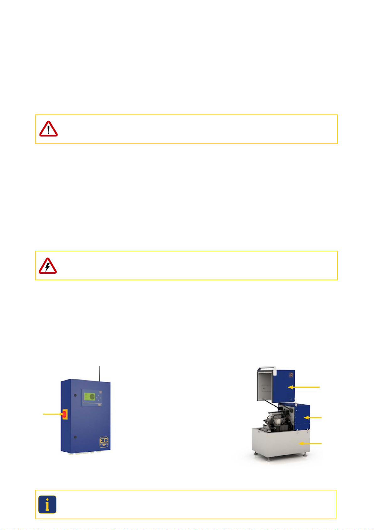
1.4
SAFETY EQUIPMENT ON THE XRGI® SYSTEM
The XRGI
®
system is equipped with a number of different safety devices that ensure its safe operation.
The safety equipment includes:
21. Master switch
22. Sound insulation panels (all casing panels)
Master switch on the iQ-Control Panel Sound insulation cladding on the Power Unit
Ensure that the warning labels (stickers) affixed to the XRGI
®
system are always clearly visible, undamaged and complete. Replace
damaged or dirty warning signs. The warning signs can be obtained from EC POWER.
Fig. 1.01 Fig. 1.02
4
MAINTENANCE INSTRUCTION
Improper service and maintenance work can affect the system function and cause damage! Installing non-approved components, as well
as unauthorized modifications and conversions, may affect safety and reduce warranty.
Only permit authorised EC POWER personnel to perform service and maintenance work.
Service and maintenance intervals must be observed.
Only original spare parts and approved equipment (such as engine oil and coolant) may be used.
The following work must be carried out with every maintenance:
Visual check
Scheduled maintenance
Preventive maintenance of the wear parts
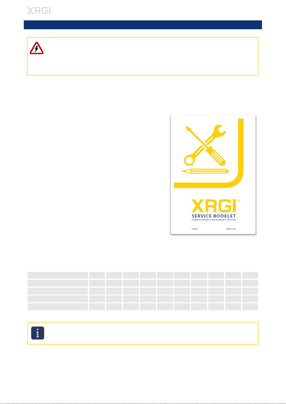
In addition, it must be confirmed in the service booklet, whether the service work
and the component replacement has been completed.
Information on the service booklet:
Acknowledge the completed service work/inspection with a check mark.
Acknowledge the service work/inspection not completed with a minus mark.
Send a manual call to the EC POWER service database before and after
every maintenance.
Acknowledge every maintenance with a signature.
Maintenance is required after fixed intervals, to ensure that the XRGI
®
system always operates safely and reliably.
The maintenance interval display on the iQ-Control Panel display as well as in the EC POWER service database also indicates this date.
MAINTENANCE INTERVAL (Maintenance is performed after the following operating hours or no later than after 2 years):
XRGI
®
-TYPE / MAINTENANCE 1. 2. 3. 4. 5. 6. 7. 8. 9. 10.
XRGI
®
6 10.000 20.000 30.000 40.000 50.000 60.000 70.000 80.000 90.000 100.000
XRGI
®
9 10.000 20.000 30.000 40.000 50.000 60.000 70.000 80.000 90.000 100.000
XRGI
®
15 8.500 17.000 25.500 34.000 42.500 51.000 59.500 68.000 76.500 85.000
XRGI
®
20 6.000 12.000 18.000 24.000 30.000 36.000 42.000 48.000 54.000 60.000
Any guarantee/warranty claims will be invalidated if maintenance is performed later than 200 operating hours after the recommended
maintenance interval.
Only use approved EC POWER spare parts and components. All guarantees and/or warranties provided will be invalidated if other com-
ponents and materials are used.
The following chapters describe the maintenance work. Follow the maintenance instructions step by step!
2. MAINTENANCE INSTRUCTION
Fig. 2.01
5
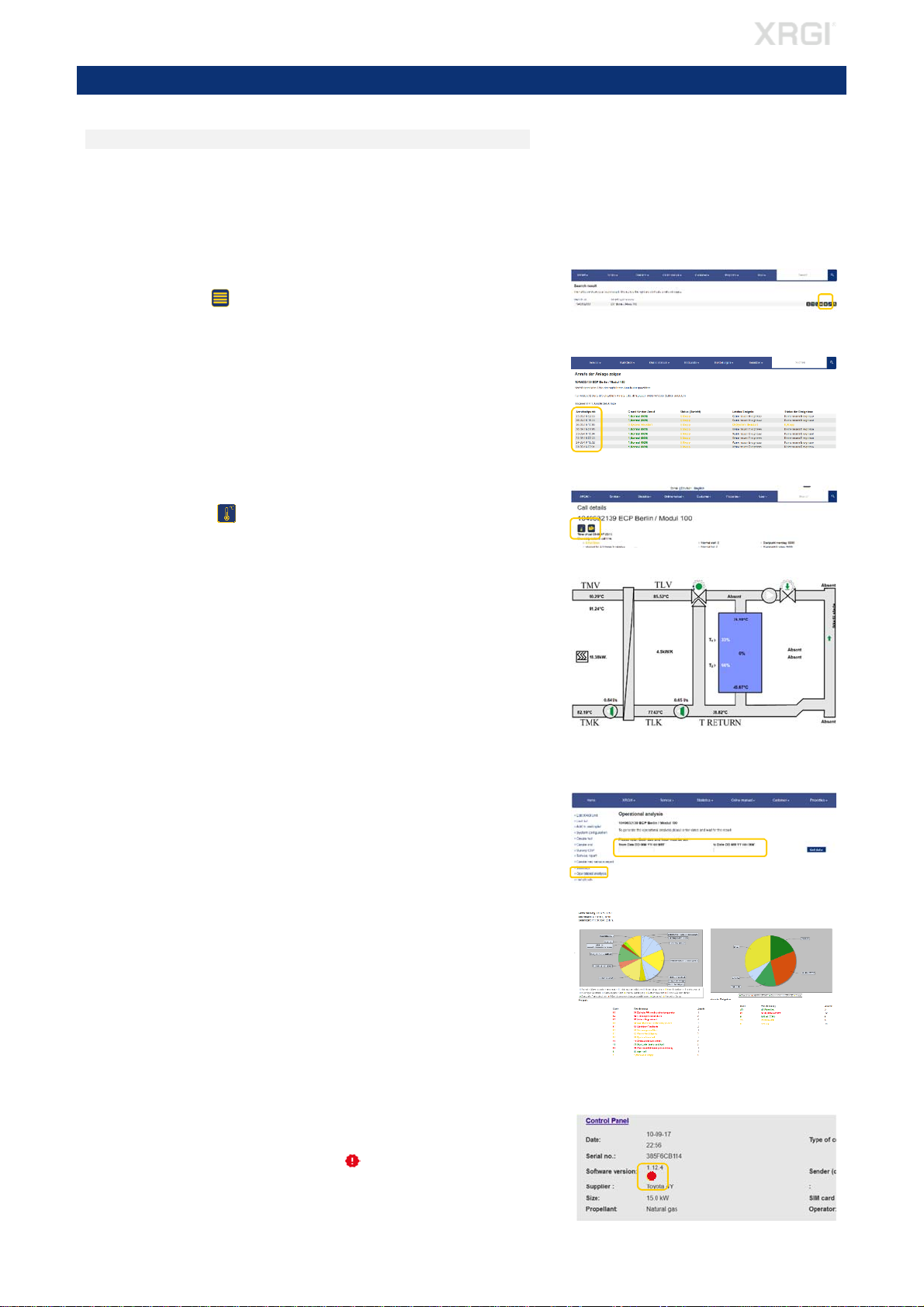
VISUAL CHECK
STEP 1 – SYSTEM OPERATION
CHECKING IN THE SERVICE DATABASE
Check the runtime of the XRGI
®
system in the EC POWER service database –
https://service.ecpower.dk
Locate the desired XRGI
®
system in the search field in the service database
by typing the XRGI
®
-ID or object name.
CALL DETAILS
Click on the icon List of calls.
Click on one Time of call to get a detailed data of that call.
Check in particular for:
most recent events/alarms.
length of operating times (under 10 minutes per start implies insuffi-
cient heat dissipation) or hydraulic problems.
STORAGE STATUS
Click on the icon Heat Distributor, to get an overview of the storage
status.
Check for abnormalities with the storage status of previous switching points.
Please pay special attention to the following:
Is the TMV set point compensated (displayed as an operational set
point below the actual value)?
Are all temperatures shown in the service database and are the figures
viable?
Is the T-Return permanently below 65 °C (max. 70 °C)?
The temperature difference between TMK - TLK is ≤ 8K at full load
when operationally warm?
OPERATING ANALYSIS
In the left menu, click on Operational analysis and enter in the 2 search
fields a period for the desired operational analysis. Click on Get data.
Check for abnormalities in the operating analysis:
- Frequent faults
- Manual switching on site
- Operating time within the reference range
SOFTWARE VERSION
Check the software version of the XRGI
®
system.
Whether a new software is available for the XRGI
®
system is displayed
in the service database with the icon under System configuration,
System list as well as Unit list.
Fig. 3.06
Fig. 3.02
3. VISUAL CHECK
Fig. 3.03
Fig. 3.04
Fig. 3.07
Fig. 3.05
Fig. 3.01
6

VISUAL CHECK
CHECKING ON SITE
Do not reach into the machine when it is in operation! Risk of injury from
hot, rotating or electrically live parts!
Check noise and smell of the XRGI
®
system.
Noise from the Power Unit with the hood closed and afterwards with the
hood open (ratting, hum).
Occurrence of exhaust gas odour.
STEP 2 – EXHAUST GAS INSTALLATION
Check whether there is a faultless certificate from the district chimney
sweeper for the flue gas line.
Check whether the flue gas system is equipped with an external exhaust
heat exchanger and whether the external exhaust heat exchanger is in-
stalled correctly on the Power Unit if necessary.
Check the condition of the flue gas line especially on wall and/or top glands.
Check the ball siphon for leaks.
While the XRGI
®
system is running, check whether condensate is present in
the ball siphon and whether condensate can run freely from the ball siphon.
Check the condensate drain for leaks.
Check the mount of the flue gas line (fastening clamps - approx. 1.5 m dis-
tance).
Check the direction and lope (> 5 cm/m) of the flue gas line.
Check whether combustion air openings on wall or doors of the installation
room of the XRGI
®
system are open.
STEP 3 – HYDRAULIC
Check that the XRGI
®
system is installed according to the EC POWER regula-
tions:
Use the commissioning protocol to check which hydraulic has been applied.
Check whether the XRGI
®
system is integrated according to the hydraulic
specified in the commissioning protocol.
Check whether changes have been made to the XRGI
®
system/installation
after commissioning.
Fig. 3.08
Fig. 3.11 Fig. 3.12
Fig. 3.10
Fig. 3.09
Fig. 3.14
Fig. 3.13
7
MAINTENANCE
Only perform maintenance work on the XRGI
®
system when it is not in
operation and is fully cooled down! Otherwise, there is a risk of burns from
hot components and/or scalding if substances should escape.
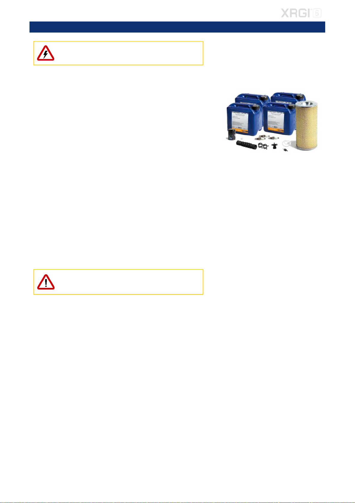
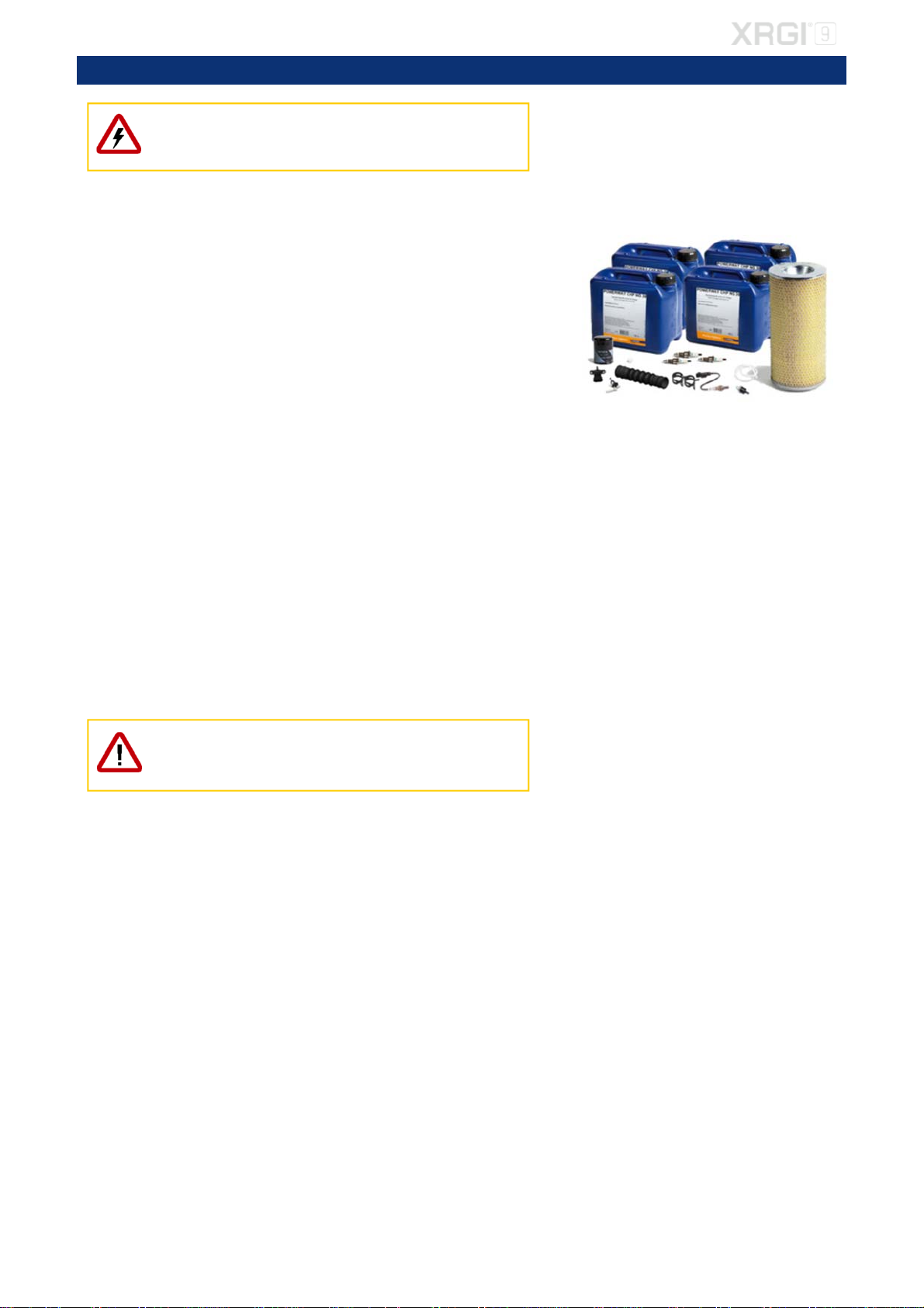
REQUIRED MATERIAL
EC POWER service kit for XRGI
®
6 (Item No.: 01KIT2611) consisting of:
1 pc. exhaust gas compensator
1 pc. vacuum sensor
2 pcs. hose clamps
1 pc. vacuum filter
1 pc. air filter
1 pc. gasket valve cover
4 pcs. engine oil
3 pcs. spark plugs
2 pcs. zero pressure hose Ø2,0x1,5
1 pc. oil filter
1 pc. plug for measuring point
REQUIRED TOOLS
Engine oil suction pump
16 mm spark plug wrench
Oil filter spanner
17 mm socket insert
Torque wrench
10 mm socket insert
Water pump pliers
3 mm Allen screwdriver
Hose clamp pliers
5 mm Allen screwdriver
Funnel
10 mm ring spanner
Feeler gauge
24 mm ring spanner
FS2009USB programming device
10 mm open-ended spanner
Flue gas analyser
17 mm open-ended spanner
19 mm open-ended spanner
10 mm socket spanner
Before commencing maintenance work, shut down the XRGI
®
system at
the user level on the iQ-Control Panel and at the main switch. Close the
gas valve and unplug the Q-Heat Distributor.
4. MAINTENANCE XRGI
®
6
Fig. 4.01
8

MAINTENANCE
4.1. SERVICE KIT - COMPONENT REPLACEMENT
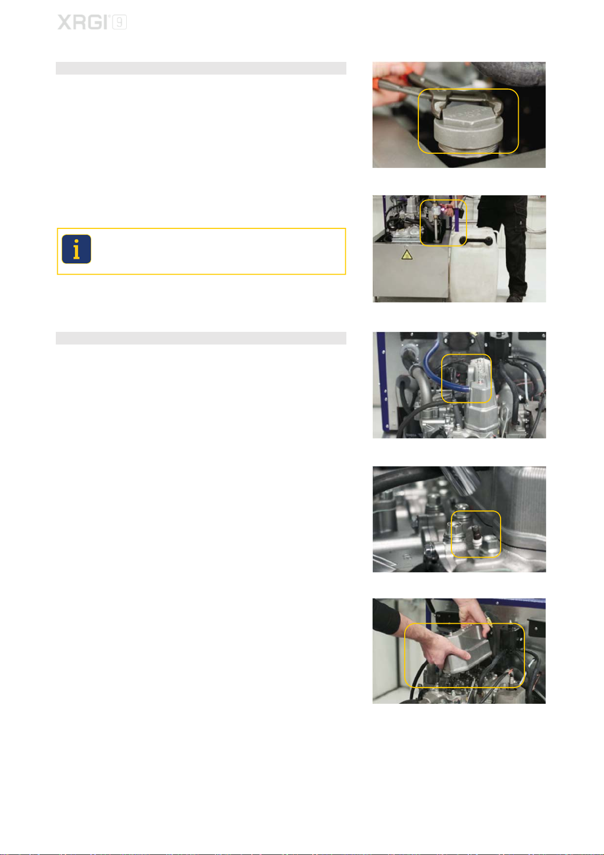
STEP 1 – USED OIL
Open the Power Unit and unscrew the oil cap with a water pump pliers.
Use a suitable suction pump for removing some of the used oil by suction.
Wait 3 to 5 minutes and then remove the remaining used oil.
Used engine oil must be disposed in accordance with the applicable coun-
try regulations. Improper disposal of used oil represents a hazard to the
environment! Mixing foreign substances such as solvents, brake fluid,
coolant and chlorinated oil in used oil is strictly prohibited!
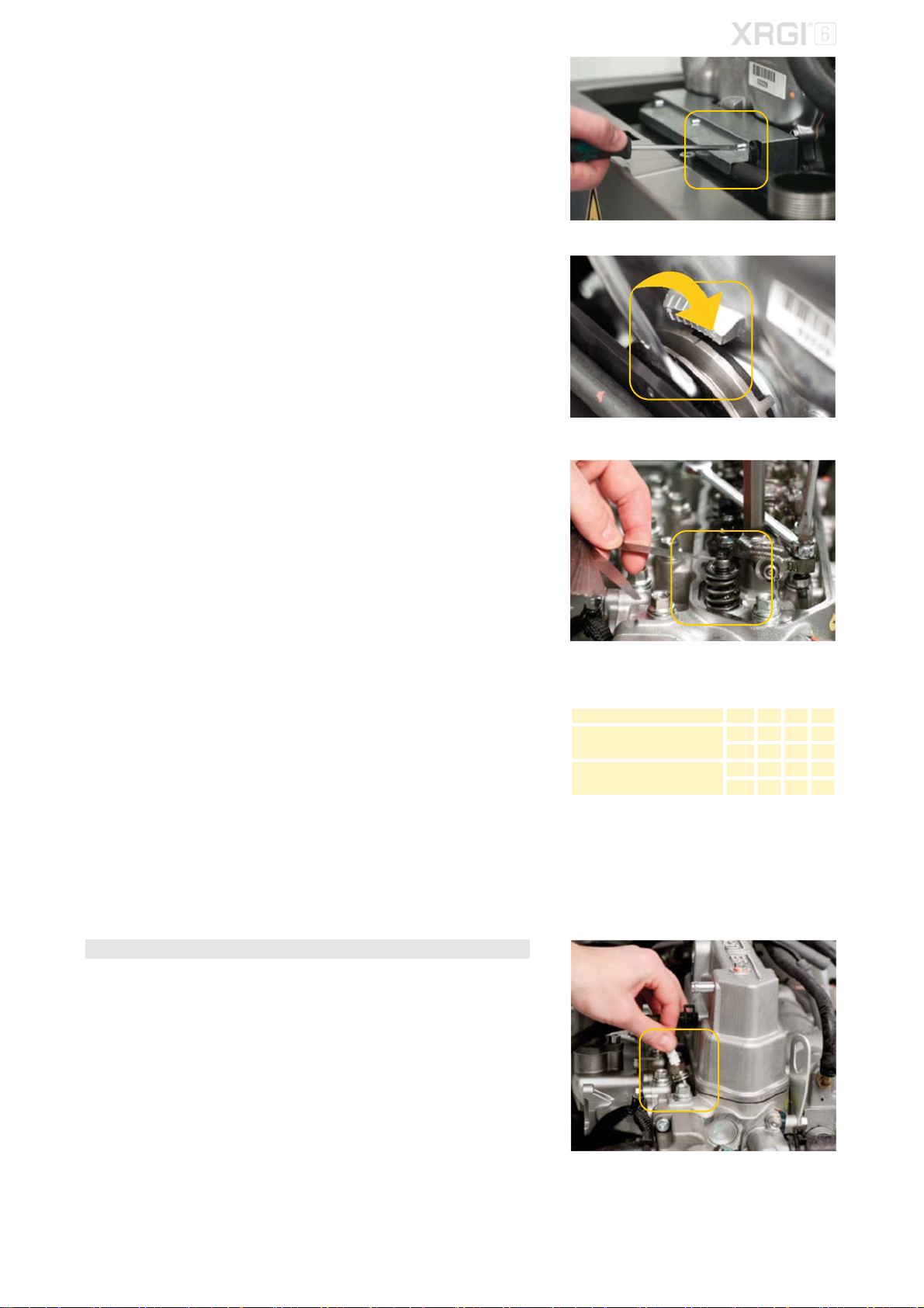
STEP 2 – VALVE CLEARANCE ADJUSTMENT
Remove the oil separator hose from the valve cover.
Remove the old spark plugs by a torque wrench with a 16 mm spark plug
insert.
Loosen the 2 bolts on the valve cover by a 10 mm socket spanner and re-
move the valve cover.
Fig. 4.02
Fig. 4.03
Fig. 4.04
Fig. 4.05
Fig. 4.06
9
MAINTENANCE
Loosen the 3 screws on the pulley cover by a 3 mm Allan screwdriver and
remove the pulley cover.
Before the valve clearance adjustment, make sure that piston No. 1 is at the
top dead centre (TDC) of the compression stroke. Rotate the crankshaft by
a 19 mm open-end spanner clockwise.
Check the valve clearance by a feeler gauge:
IN 0.20 mm (cool engine)
EX 0.20 mm (cool engine)
If deviations occur, adjust the valve clearance.
Valve clearance adjustment
Loosen the lock nut by a 10 mm ring spanner and turn the adjusting screw
for adjustment.
Tighten the locknut by a torque wrench with a 10 mm socket insert and
check the valve clearance again.
Torque: 11 Nm
With No. 1 piston at TDC of the compression stroke, check and adjust the
valve clearances for the cylinders shown in the chart to the right.
Rotate the crankshaft one complete turn (360°) clockwise to check and ad-
just the remaining valves.
Replace the old valve cover gasket with the new gasket and reinstall the
valve cover with the 2 bolts.
Torque: 10.5 ± 0.05 Nm
Fasten the pulley cover with the 3 screws.
STEP 2 – USED SPARK PLUGS
Use a feeler gauge to check the electrode gap before inserting the new
spark plugs and adjust if necessary.
Standard gap: 0.4 – 0.5 mm
Insert the new spark plugs loosely to allow the temperature to balance out
between the cylinder head and spark plugs.
Fig. 4.07
Fig. 4.08
Fig. 4.09
Table 1
Piston position cylinder 1 2 3
No. 1 piston at TDC, of
compression stroke
IN ● ●
EX ● ●
Rotate crankshaft 360º
clockwise
IN ●
EX ●
Fig. 4.10
Fig. 4.11
10

MAINTENANCE
STEP 4 – AIR FILTER
Loosen the screws of the rear cover of the Power Unit by a 3 mm Allen
screwdriver and remove the rear cover.
Loosen the fixing bolt on the air filter cover by a 17 mm open-end spanner
and remove the cover.
Loosen the fixing bolt on the air filter by a 17 mm open-end spanner and
pull the air filter off the threaded rod.
Install the new air filter and put the air filter cover back on − tighten the bolt
by a torque wrench with a 17 mm socket insert.
Torque: 5 Nm.
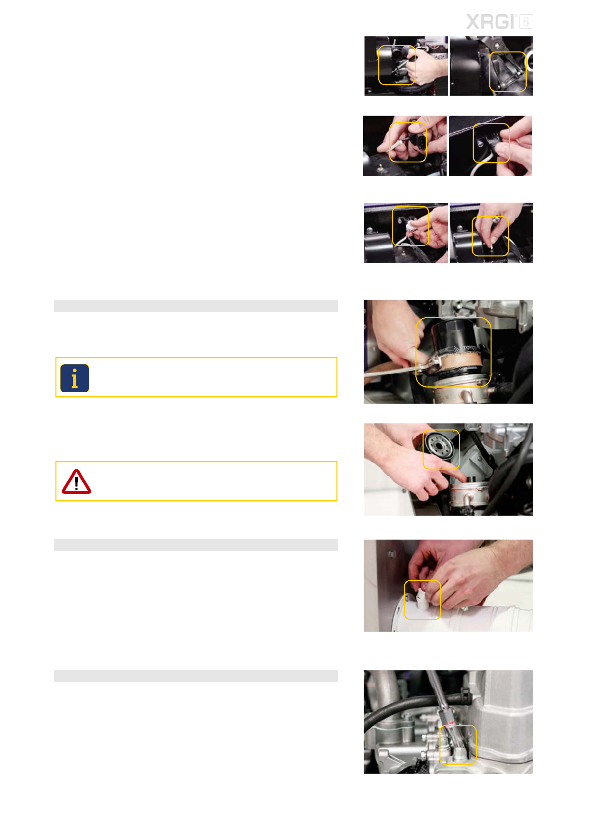
STEP 5 - ZERO PRESSURE HOSE, VACUUM FILTER & VACUUM SENSOR
Remove the plug from the vacuum sensor and the zero pressure hose from
the air filter box.
Unscrew the vacuum sensor by a 5 mm Allen screwdriver and remove it
from the zero pressure hose.
Remove the 2 hose clamps by a hose clamp pliers from the MGB hose and
pull it from the intake socket.
Loosen the 3 bolts for the air filter box by a 10 mm socket spanner and
remove the box together with the oil separator hose.
Pull the zero pressure hose from the vacuum filter and unscrew it from the
intake manifold by a 24 mm ring spanner.
Insert the new vacuum filter by a 24 mm ring spanner and put the zero pres-
sure hose back onto the vacuum filter.
Fig. 4.12
Fig. 4.13 Fig. 4.14
Fig. 4.15 Fig. 4.16
Fig. 4.17 Fig. 4.18
Fig. 4.19 Fig. 4.20
Fig. 4.21
Fig. 4.22
Fig. 4.23 Fig. 4.24
11
MAINTENANCE
Put the air filter box and the oil separator hose back into their positions and
fix the air filter box bolts by a 10 mm open-end spanner.
Put the MGB hose back into the intake sockets and use the 2 spring hose
clamps to fix it by a hose clamp pliers.
Push the zero pressure hose onto the new vacuum sensor and fasten the
vacuum sensor by a 5 mm Allen screwdriver.
Put the plug back onto the vacuum sensor and the zero pressure hose back
onto the air filter box.
STEP 6 – OIL FILTER
Dismantle the used oil filter by an oil filter spanner.
Used filters must be disposed in accordance with the applicable country
regulations. Improper disposal of used filters represents a hazard to the
environment!
Take the new oil filter, put a little oil onto the rubber seal and tighten the oil
filter manually.
Do not use any tools to fit the oil filter as they could damage it!
STEP 7 – PLUG FOR MEASURING POINT
Depending on the type of exhaust gas pipe, consider replacing the plug in
the exhaust gas opening on the exhaust gas pipe upstream of the Power
Unit.
STEP 8 – NEW SPARK PLUGS
The temperatures of the spark plugs and the cylinder head have now equalised.
Fasten the new spark plugs by a torque wrench with a 16 mm spark plug
insert and put the spark plug cap back on.
Torque: 18 Nm.
Fig. 4.31
Fig. 4.32
Fig. 4.33
Fig. 4.34
Fig. 4.25 Fig. 4.26
Fig. 4.27 Fig. 4.28
Fig. 4.29 Fig. 4.30
12
MAINTENANCE
Push the oil separator hose onto the valve cover.
STEP 9 – EXHAUST GAS COMPENSATOR & HOSE CLAMPS
Loosen the hose clamps on the exhaust gas compensator by a hose clamp
pliers and put them aside.
Remove the exhaust gas compensator together with the two hose clamps
from both ends of the pipe.
Replace the exhaust gas compensator including the two hose clamps and
fix the exhaust gas compensator with the 2 hose clamps by a hose clamp
pliers.
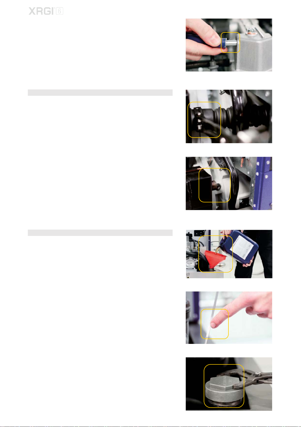
STEP 10 – OIL
Add oil to the engine. Fill a maximum of 40 litres of oil through the filler neck.
Use a funnel to fill the engine.
Check the oil level on the dipstick to ensure that the engine is not overfilled.
To do this, briefly screw on the oil cover and then take it off again.
After checking the oil level, fasten the oil cap by a water pump pliers.
Fig. 4.35
Fig. 4.36
Fig. 4.37
Fig. 4.38
Fig. 4.39
Fig. 4.40
13

MAINTENANCE
4.2. SOFTWARE UPDATE
If your XRGI
®
system already has the latest software installed, please
proceed to section 4.3. REGULATION OF EMISSIONS.
STEP 1 – SYSTEM DATA
Once the software has been updated, all settings and operational para-
meters are set to factory settings.
Software-Release 1.14.6 (or higher): after the software update, recover
all system data with the configuration request function.
Before updating the software, note all current settings and operational parame-
ters of the XRGI
®
system. Please refer to the main menu under Info and in the
technician menu under Settings.
Press any key on the user interface to activate the display and enter the
menu.
Move the cursor to Info by using the ▲▼ buttons and press OK on the user
interface.
Press ESC on the user interface to return to the menu.
Move the cursor to Technician by using the ▲▼ buttons and press OK on
the user interface.
Log on.
In the technician menu, move the cursor to Setup by using the ▲▼ buttons
and press OK on the user interface.
STEP 2 – DATA TRANSMISSION
Ensure that the latest data from the XRGI
®
system are send to the EC POWER
service database by making a manual modem call before the software update.
In the main menu, move the cursor to Modem call by using the ▲▼ buttons
and press OK on the user interface.
Fig. 4.41
Fig. 4.42
Fig. 4.43
Fig. 4.44 Fig. 4.45 Fig. 4.46
Fig. 4.47
14

MAINTENANCE
Move the cursor to Send by using the ▲▼ buttons and press OK on the
user interface. The communication system will be initialised.
FOR SOFTWARE RELEASE 1.14.6 (OR HIGHER) ONLY!
If it is not possible to make a manual modem call, please note all settings
and operating parameters of the XRGI
®
system before the software update
on the form REQUEST DATA MODIFICATION and send the form to the
EC POWER customer service ([email protected]k).
The submitted data will be transferred to the XRGI
®
system after verifica-
tion by EC POWER.
The connection is being established. All data have been received. The connection is being established.
STEP 3 – NETWORK CABLES
Disconnect the network communication to avoid any interference between the
XRGI
®
system components.
Remove all network cables between the Power Unit, iQ-Control Panel and
Q-Heat Distributor and cover all unused RJ45 plugs with RJ45 ISDN net-
work terminators.
iQ-Control Panel Power Unit Q-Heat Distributor
STEP 4 – SOFTWARE UPDATE XRGI® SYSTEM
Software update of the XRGI
®
system requires that the boards of all XRGI
®
components must be updated, otherwise the XRGI
®
system may malfunc-
tion.
Update the heat control
PCB
of the Q-Heat Distributor, the central control
PCB
of the iQ-Control Panel and the ECU
PCB
or the gas safety
PCB
of the
Power Unit.
Use the FS2009USB programming device.
The ECU PCB has to be updated at 3 places (in priority order: J12, J19
and J20), the heat control PCB (Q40/Q50/Q60) at 2 places (J3 Heat
Control UART and J1 Heat Control) and all other PCB’s at 1 place.
STEP 5 – SOFTWARE UPDATE Q-NETWORK MODULES
After completing the software update of the XRGI
®
system, remove all RJ45
terminators and reconnect all network cables.
Update all b
PCB’
s of the Q-Network modules connected to the XRGI
®
sys-
tem.
Please note that Q-Network modules run on PoE sorce (Power over Ether-
net). Thus, after updating the Q-Heat Distributor, restore the network con-
nections in order to update the Q-Network modules such as Storage Con-
trol and Flow Control.
Fig. 4.53 Fig. 4.54 Fig. 4.55
Fig. 4.56
Q-Network modules
Flow Control VPP Gateway
Boiler Control Modbus Gateway
Storage Control Load Sharer S
Flow Master Control Electric Heater Control
Aux Temp Tracker Fig. 4.57
Fig. 4.48
Fig. 4.49 Fig. 4.50 Fig. 4.51 Fig. 4.52
15

MAINTENANCE
STEP 6 – DATA RECOVERY
Recover all data from the XRGI
®
system.
In the technician menu, move the cursor to Setup by using the ▲▼ buttons
and press OK on the user interface.
Move the cursor to XRGI-ID by using the ▲▼buttons and enter the XRGI
®
-
ID of the XRGI
®
system by using the ▲▼ and ENTER buttons.
Move the cursor to APN by using the ▲▼ buttons and enter the APN ad-
dress of the inserted SIM card.
EC POWER Telia SIM card: internet.ts.m2m
When using another SIM card than an EC POWER Telia SIM card, please
contact the SIM card provider for the APN address.
An incorrect APN address causes data transfer problems.
Move the cursor to Request by using the ▲▼ buttons and press ENTER
on the user interface.
Manual configuration may only be used when commissioning new
XRGI
®
systems, not during the software update of existing XRGI
®
sys-
tems.
The data from the XRGI
®
system will now be recovered and visible on the display
after a few minutes. Check that all data are the same as those noted before the
software update.
If the data are incorrect, please contact the EC POWER customer service at
support@ecpower.dk
Fig. 4.58
Fig. 4.59
16
MAINTENANCE
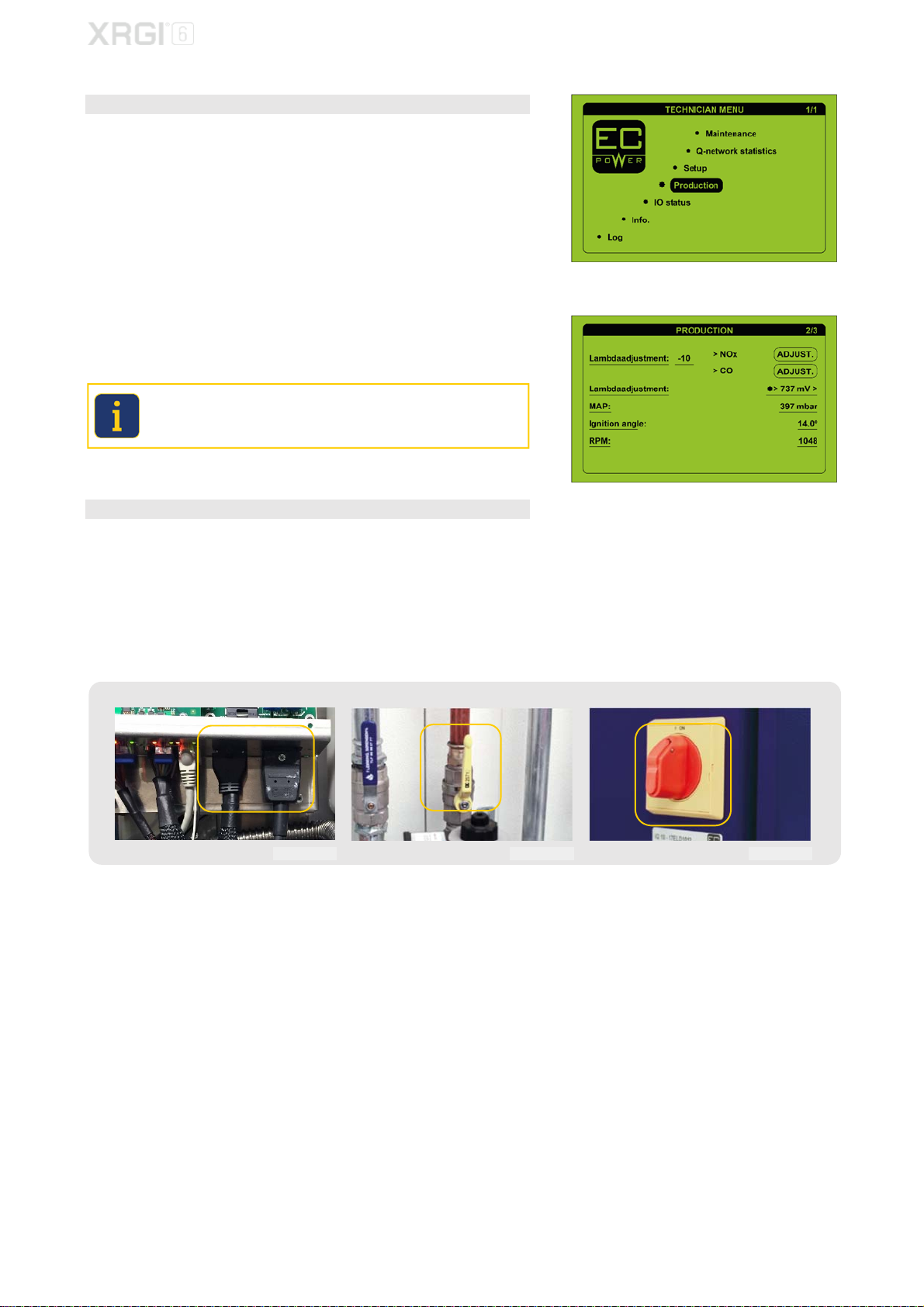
4.3. REGULATION OF EMISSIONS
STEP 1 – LAMBDA ADJUSTMENT
In the technician menu, move the cursor to Production by using the ▲▼
buttons and press OK on the user interface.
Use the ▲▼ buttons to enter the lambda adjustment page.
Operate the flue gas analyser in line with the manufacturer’s instructions
and measure the flue gas emission.
If the flue gas emissions are outside the required range, adjust the settings
under Lambda adjustment.
CO: max. 75 ppm
NO
X
: max. 50 ppm
If the CO values are too high/low, press:
CO ADJUST = Lambda adjustment decrease by -1
NO
X
ADJUST = Lambda adjustment increase by +1
When reducing CO and/or NOx values it takes a couple of minutes before
the change stabilises on your flue gas analyser. Only make small adjust-
ments at a time in order to achieve the correct values.
STEP 2 – RECOMMISSIONING
Once all parts of the service kit have been replaced on the XRGI
®
system
and the latest software version has been played on all components, close
the Power Unit and reinstall the rear cover of the Power Unit.
Recommission the XRGI
®
system by:
- Connecting the Q-Heat Distributor to the power supply.
- Opening the gas supply to the Power Unit.
- Switching on the XRGI
®
system on the iQ-Control Panel.
Q-Heat Distributor Gas valve Main switch
Fig. 4.62 Fig. 4.63 Fig. 4.64
Fig. 4.60
Fig. 4.61
17
MAINTENANCE
Only perform maintenance work on the XRGI
®
system when it is not in
operation and is fully cooled down! Otherwise, there is a risk of burns from
hot components and/or scalding if substances should escape.
REQUIRED MATERIAL
EC POWER service kit for XRGI
®
9 (Item No.: 01KIT2612) consisting of:
1 pc. exhaust gas compensator
1 pc. plug for measuring point
2 pcs. hose clamps
1 pc. vacuum sensor
1 pc. injector
1 pc. vacuum filter
1 pc. lambda sensor
1 pc. gasket valve cover
1 pc. air filter
3 pcs. spark plugs
4 pcs. engine oil
1 pc. oil filter
2 pcs. zero pressure hose Ø2,0x1,5
REQUIRED TOOLS
Oil suction pump
16 mm spark plug wrench
Oil filter spanner
17 mm socket insert
Torque wrench
10 mm socket insert
Water pump pliers
3 mm Allen screwdriver
Hose clamp pliers
5 mm Allen screwdriver
Funnel
10 mm ring spanner
Feeler gauge
24 mm ring spanner
FS2009USB programming device.
10 mm open-ended spanner
Flue gas analyser
17 mm open-ended spanner
Lambda sensor top long ½
19 mm open-ended spanner
10 mm socket spanner
Before commencing maintenance work, shut down the XRGI
®
system at
the user level on the iQ-Control Panel and at the main switch. Close the
gas valve and unplug the Q-Heat Distributor.
5. MAINTENANCE XRGI
®
9
Fig. 5.01
18
MAINTENANCE
5.1 SERVICE KIT - COMPONENT REPLACEMENT
STEP 1 – USED OIL
Open the Power Unit and unscrew the oil cap with a water pump pliers.
Use a suitable suction pump for removing some of the used oil by suction.
Wait 3 to 5 minutes and then draw off the remaining used oil.
Used engine oil must be disposed in accordance with the applicable coun-
try regulations. Improper disposal of used oil represents a hazard to the
environment! Mixing foreign substances such as solvents, brake fluid,
coolant and chlorinated oil in used oil is strictly prohibited!
STEP 2 – VALVE CLEARANCE ADJUSTMENT
Remove the oil separator hose from the valve cover.
Remove the old spark plugs with a torque wrench with a 16 mm spark plug
insert.
Loosen the 2 bolts on the valve cover by a 10 mm socket spanner and re-
move the valve cover.
Fig. 5.02
Fig. 5.03
Fig. 5.04
Fig. 5.05
Fig. 5.06
19
Other manuals for XRGI 6
1
This manual suits for next models
3
Table of contents
Other EC POWER Industrial Equipment manuals


