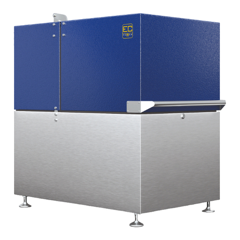
EC POWER XRGI 20G-TO User manual

SyStem componentS & InStallatIon InStRUctIonS

2
VERSION 1.0 - 2012MANUAL XRGI 20G-TO

3
VERSION 1.0 - 2012 MANUAL XRGI 20G-TO
This manual informs you in detail about the system components and about how to install your new XRGI 20G-TO. It also gives
important safety instructions that must adhered to when the XRGI system is used. The manual includes descriptions of the
main XRGI system components, i.e. Power Unit, Q60-Heat Distributor and IQ-Control Panel, and of the XRGI system accesso-
ries, i.e. Q-Network, Load Sharer and storage tank, which are not included in the supply and must be purchased individually.
The performance of the XRGI system depends very much on how it is used: we recommend you read the manual carefully
before using the XRGI. This will make you familiar with how exactly the XRGI system works and ensures the manufacturer's
warranty is not invalidated. Please keep the manual for later reference.
EC POWER A/S continues to improve its products. The company reserves the right to make changes and improvements if it
considers this to be necessary. This does not mean the company is bound to make changes to XRGI systems we have already
supplied.
If you have additional questions, please do not hesitate to get in touch with your dealer.
Enjoy using your XRGI 20G-TO.
Do not forget to read the operating and safety instructions before using the machine.
System model:
PU no.:
XRGI ID:
First used:
SyStem data
EC POWER A/S
Samsøvej 25
8382 HINNERUP
DENMARK
Tel. +45 87 43 41 00

4
VERSION 1.0 - 2012MANUAL XRGI 20G-TO
Everything we do is guided by our concern for safety and for the environment.
We meet expectations.
We treat our clients as part of the EC POWER family.
We are innovative.
Congratulations on your purchase of the XRGI system. It
offers an economically viable solution to lower your energy
costs in an environmentally friendly way. Using the principle
of combined heat and power generation, the XRGI system
achieves an efciency of up to 96 % and thus helps save
resources and to protect the environment. In addition, it re-
duces your energy costs noticeably. What's unusual about
this tried and tested method is that you can use the gene-
rated heat to produce electricity, instead of wasting it by
releasing it into the atmosphere where it can do harm. This
is why CHP is rightly seen as the sustainable energy pro-
duction of the future. It contributes actively to protecting the
environment. This is why environmentalists welcome it and
the Federal Government supports it. CHP stands out when
it comes to ‘green’ energy production methods. Unlike so-
lar and wind power, CHP does not depend on the weather.
Modular CHP units save resources whatever the weather
and provide a reliable supply of electricity and heat. You will
always have power and heat at hand – reliably!
Denmark began using CHP in the 1950s, so it has acquired
a lot of experience and competence in this eld. In 1996
a group of Danish engineers decided to make use of this
experience and teamed up to found EC POWER. One of
the goals of EC POWER is to make optimal use of primary
energy in order to cover growing electricity requirements
cost-effectively while lowering the environmental impact. In
order to meet the growing needs of the market, EC POW-
ER subsequently founded a subsidiary in Germany. Today,
EC POWER is one of Europe's leading manufacturers of
modular CHP units in the 10-50 kWel class, and our XRGI
systems are sold in more than ten European countries.
Foreword
our hiStory
our valueS aS a company

5
VERSION 1.0 - 2012 MANUAL XRGI 20G-TO
1. General instructions 8
1.1. Notes on equipment documentation 9
1.1.1. Symbols used 9
1.1.2. Other applicable documents 9
1.2. Handling the equipment 10
1.2.1. Operator's obligations 10
1.2.2. Rules and standards 10
1.2.2.1. Modifying XRGI system components 11
1.2.3. Warranty instructions 11
1.2.3.1. Rescission and complaints 11
1.2.4. What to do in the event of an emergency 12
1.2.4.1. Gas smell 12
1.2.4.2. Fire or water ingress 12
1.2.4.3. Flue gas smell 12
1.2.5. Frost protection 13
1.2.6. Contact risks 13
1.2.7. Combustion air supply 13
1.2.8. Filling and top-up water 14
1.2.9. Installation 15
1.2.10. Installation area and space required 15
1.2.10.1. Alterations in system surroundings 16
1.2.10.2. Explosive and highly inammable substances 16
1.2.11. Transportation and accommodation 16
1.2.12. Base 16
1.2.13. Soundproong 17
2. XRGI 20G-TO system components 18
2.1. Main XRGI system components 18
2.1.1. Power Unit 20G-TO 19
2.1.1.1 Structure 19
2.1.1.2. Dimensions and connections 20
2.1.1.3. Functioning 21
2.1.1.4. Settings 21
2.1.1.5. Technical data 21
2.1.2. IQ-Control Panel 22
2.1.2.1. Structure 22
2.1.2.2. Dimensions and connections 22
2.1.2.3. Functions 23
2.1.2.4. Settings 23
2.1.2.5. Technical data 23
2.1.3. Q60-Heat Distributor 24
2.1.3.1. Structure 24
2.1.3.2. Dimensions and connections 25
2.1.3.3. Function 26
2.1.3.4. Settings 26
2.1.3.5. Technical data 26
2.2. XRGI system accessories 27
2.2.1. Q-Network 27
2.2.2.1. Storage Control 28
2.2.1.2. Flow Control 29
2.2.1.3. Boiler Control 30
2.2.1.4. Storage Tank 31
2.2.1.5. Q-Network wiring 33
2.2.2. Power-controlled operation 35
2.2.2.1. Load Sharer 35
table oF contentS

6
VERSION 1.0 - 2012MANUAL XRGI 20G-TO
3. Installation instructions 39
3.1. Installing XRGI system components 39
3.2. General installation instructions 40
3.2.1. Location 40
3.2.1.1. Foundations 40
3.2.1.2. Room temperature/dust 40
3.2.1.3. Exhaust gases 40
3.2.1.4. Noise/vibration 41
3.2.1.5. Corrosive ambient conditions 41
3.2.1.6. Required air inlet 41
3.2.2. Setting up XRGI 20G-TO 41
3.2.2.1. Setting up the system 41
3.3. Installing your XRGI 20G-TO 42
3.3.1. Power Unit connections 42
3.3.1.1. Gas connection 43
3.3.1.2. Hydraulic connection 43
3.3.1.3. Exhaust connection 44
3.3.1.4. Exhaust gas heat exchanger 45
3.3.1.5. Electrical connections 45
3.3.2. Q60-Heat Distributor connections 46
3.3.2.1. Return water temperature 46
3.3.2.2. Hydraulic connections 46
3.3.2.3. Electrical connections 46
3.3.3. IQ-Control Panel connections 47
3.3.3.1. Electrical connections 47
3.3.3.2. Reactive current compensation 48
3.3.3.3. External connections 49
3.3.3.4. Remote data transmission 50
3.3.4. Storage tank connections 50
3.3.5. Connecting Q-Network Modules and Load Sharer 52
3.3.5.1. Flow Control 52
3.3.5.2. Storage Control 53
3.3.5.3. Boiler Control 54
3.3.5.4. Load Sharer 55
3.4. Hydraulic integration of the XRGI 20G-TO 56
3.4.1. System temperatures 56
3.4.2. Selecting the right hydraulics 56
3.4.2.1. Basic hydraulic circuits of XRGI components 56
3.4.3. Integration into heating system 56
3.4.3.1 Parallel integration with or without Flow Control 56
Parallel integration with Flow Control (Installation 1) 57
Parallel integration without Flow Control for multiple systems (Installation 2) 58
Heating return increase with Flow Control (Installation 3) 59
Heating return increase for multiple systems (Installation 4) 59
3.4.4. Transmitting heat to the consumer side 60
3.4.4.1. Overows 60
3.4.4.2. Hot water production 60
3.4.5. Indications of lack of hydraulic equalization 61
3.4.6. Summary 61
3.5. Control strategy 61
3.5.1. Heat-controlled operation 62
3.5.2. Tariff-oriented operation 63
3.5.3. Power-controlled operation 64
3.5.4. Heat-controlled, power-controlled operation 65
3.6. Electrical installation of the XRGI 20G-TO 66

7
VERSION 1.0 - 2012 MANUAL XRGI 20G-TO
4. Operating instructions 68
4.1. User interface on IQ-Control Panel 68
4.1.1. Control keys 68
4.1.2. Display 68
4.1.3. Starting and stopping automatic operation 69
4.1.3.1. Manual stop 69
4.1.3.2. Manual start 69
4.1.3.3. Automatic operation 70
4.1.3.4. Alarm stop 71
4.1.4. Power statistics 71
4.1.4.1. 24-hour statistics 72
4.1.4.2. Weekly statistics 72
4.1.5. Storage tank and heat production 73
4.1.6. Operating data 74
4.1.7. Operating data online 75
4.1.8. Heat & Tariff 75
4.1.8.1 Heat backup 75
4.1.8.2. HT period 76
4.1.9. Load proles and heat-controlled 76
4.1.9.1. Load proles 77
4.1.9.2. Heat-controlled 78
4.1.10. Power sales 80
4.1.11. Modem calls 81
4.1.12. Technician 82
5. Pre-commissioning 82
5.1. Registering new XRGI site in the Service Database 82
5.2. Checklist 85
6. Monitoring 86
6.1. Troubleshooting 86
6.1.1. Your XRGI 20G-TO system does not start 86
6.2. Service codes 86
6.2.1. Service 87
6.2.2. Operating modes 94
6.2.3. Reasons for calls 95
7. Care and maintenance 96
7.1. Care 96
7.2. Maintenance 97
7.2.1. Display of maintenance requirements 97
anneXeS
1. XRGI Control Panel 99
2. XRGI external connections 131
3. Declaration of conformity 161
4. Certicate of no objection 11030 162
5. Pre-commissioning checklist 163

8
VERSION 1.0 - 2012MANUAL XRGI 20G-TO
Warning! EC POWER assumes no liability for any damage caused by non-compliance with these instructions.
We reserve the right to make technical changes
Continuous development means that illustrations, procedures and technical data may vary slightly.
1. General inStructionS
You have acquired a quality product by EC POWER. Your
XRGI 20G-TO system will provide you with the benets you
expect if it is cared for and properly maintained.
Using the system in any way other than described below
constitutes misuse and is prohibited.
The XRGI 20G-TO is a [combined] heat and power gene-
ration system, and must be used for this purpose only. The
XRGI system must be installed in accordance with the as-
sembly and operating instructions.
The XRGI and its associated components must be assem-
bled, commissioned, serviced and repaired by authorised
EC POWER specialists only. Using it improperly may lead
to irreparable damages. We will not accept any liability for
any damage that occurs as a result of improper use of the
XRGI system.
The XRGI 20G-TO must only be used in combinations ap-
proved by the manufacturer and with the accessories and
spare parts stated in the assembly and commissioning inst-
ructions. Any other combinations, accessories and wearing
parts may only be used if they are expressly intended for
the proposed use and they do not affect the performance
characteristics or safety requirements of the XRGI 20G-TO.
The XRGI 20G-TO must be maintained and checked in ac-
cordance with the intervals specied, otherwise any claims
asserted under warranty will lapse. Please have your autho-
rised EC POWER specialist carry out the maintenance work
and inspections.
The XRGI 20G-TO must be protected from frost. The ma-
nufacturer will not be liable for frost damage.
You must follow the operating instructions when adjusting
parameters.
If your XRGI 20G-TO has been out of use for a prolonged
time period, you need to ensure that the condensate drain
is lled with water.
Check the water level in the system regularly, and have any
leaks dealt with by your authorised EC POWER specialist.

9
VERSION 1.0 - 2012 MANUAL XRGI 20G-TO
1.1. noteS on equipment documentation
1.1.2. Other applicable documents
1.1.1. Symbols used
Please follow the safety instructions given in this manual when using your XRGI system. The following symbols are used in this
manual:
Note!
Useful information and instructions
Warning!
Potentially hazardous situation for the product and the environment!
Danger!
Immediate threat to life and limb!
For the system operator:
1 Manual
For the specialised mechanic:
1 Assembly instructions
Scope of this manual
This manual applies to the XRGI 20G-TO
without accessories
with additional storage tank
Before assembling and installing the XRGI 20G-TO, read the assembly instructions carefully and follow the safety instructions
there given.
Note: please keep these documents for future reference.

10
VERSION 1.0 - 2012MANUAL XRGI 20G-TO
1.2. handlinG the equipment
To take best advantage of all the benets your XRGI 20G-TO offers, please read these instructions carefully. For your own
safety, please note that your system must be set up and adjusted by an authorised EC POWER specialist only. The same ap-
plies for inspection/maintenance, servicing and repairs of the device. For a long, reliable service life, please note the following:
Have your unit inspected and maintained by an authorised EC POWER specialist at least every two years.
Keep the air inlets in walls or doors clear.
Installation is governed in particular by the rules, regulations and guidelines below:
Federal State building regulations
MFeuVo model re regulations and/or Federal State FeuVO
BImSchV Federal emission protection regulations
Energy saving law (EnEG) and heating system regulations issued pursuant to it (HeizAnlV)
Technical rules for gas installations DVGW-TRGI 86, current edition, Wirtschafts- und Verlagsgesellschaft Gas und
Wasser mbH., Bonn
DVGW worksheet G600 (TRGI)
DIN 1988 Technical rules for drinking water installations (TRWI)
DIN 4701 Rules for calculating building heating requirements
DIN 4751 Bl. 3 Safety equipment for heating systems with lead temperatures up to 110 °C
ATV worksheet A 251 Feeding condensation water from gas- and oil-red heating systems into the public drains and micro-
treatment plants, November 1998 edition, GFA Verlag für Abwasser, Abfall und Gewässerschutz, Hennef
Regulations on energy saving heat protection and building systems (energy saving regulations - EnEV) 16 November 2001
DIN VDE 0100 (Parts 540 and 701 in particular) and DIN VDE 0105.
Guidelines for connecting and operating local generation systems in the low voltage network of the association of German
electricity works – VDEW – e.V.
Technical connection requirements for connecting to the low voltage network of the association of German electricity works
– VDEW – e.V.
Warning! Safety devices must not be disabled, bypassed or removed.
1.2.1. Operator's obligations
1.2.2. Rules and standards
Danger! All connections (fuel, ue gas and electrical) as well as the initial commissioning, maintenance and
repairs must be carried out by authorised personnel only. In addition, the generally recognised technical
and architectural rules must be observed. Safety devices must be installed in accordance with local rules.
Observe Health and Safety at Work Regulations.

11
VERSION 1.0 - 2012 MANUAL XRGI 20G-TO
1.2.3. Warranty instructions
1.2.3.1. Rescission and complaints
1.2.2.1. Modifying XRGI system components
XRGI system components must not be modied without EC POWER's prior consent in writing.
Install and operate the system professionally and in accordance with current EC POWER instructions.
Have the system serviced regularly and in accordance with current servicing instructions. Servicing may be carried out by
trained and authorised EC POWER specialists only.
Warranty exclusions:
In particular, losses over which the manufacturers have no direct or indirect control, such as:
faulty design and installation (e.g. fuel supply, hydraulic/electrical connections, ue gas extraction)
commissioning, servicing and repairs by purchasers and third parties
natural wear and tear
faulty, negligent treatment, alterations, repairs
unsuitable equipment/material, unauthorised lubricants
use of heating water that does not meet applicable technical guidelines
chemical, electrochemical and electrical inuences
use of drinking water that is not in accordance with the generally recognised technical rules
The warranty provisions specied in the general terms and conditions of EC POWER A/S and EC POWER GmbH in the current
version apply.
Should the XRGI system be defective in fact or law (hereinafter: 'defective') at the time of delivery and should the cause for this
defectiveness already have existed at the time of the passage of risk, the Purchaser will be entitled to subsequent performance,
at the discretion of EC POWER, either by having the defect remedied or by delivering a substitute device. Should subsequent
performance fail, the Purchaser may reduce payment or rescind the contract at his discretion (T&Cs section 8).
We cannot accept liability for any defects which are the result of (T&Cs section 7):
improper use, incorrect assembly and/or commissioning, negligent operation or use of unsuitable equipment/material,
lubricants, lubricant additives, water and/or replacements by the Purchaser or third parties, natural wear and tear, faulty
construction work, chemical, electrochemical or electrical inuences;
the Purchaser failing to meet his obligations to investigate and complain duly under § 377 of the Commercial Code [HGB].
Notice of any defects must be given in writing within 10 days of receiving the supplied goods at their destination or, if they
could not be detected by due examination, within 10 days of their being discovered;
the Purchaser being in arrears with payment.

12
VERSION 1.0 - 2012MANUAL XRGI 20G-TO
In the event of gas smell, please proceed as follows:
Do not operate any electrical switches or remove any power plugs.
Do not operate any electric bells.
Do not use matches or lighters.
Do not smoke.
Do not use any telephone, radio telephone or mobile phone in the risk area.
Open all doors and windows immediately.
Extinguish all ames immediately.
Close the stop-cock on the gas meter or main stop-cock in the basement immediately.
Having closed the main stop-cock, close the gas stop-cock on the XRGI connection panel and check that the gas ttings
of all other equipment are closed. Close all gas ttings that are still open (pilot lights, gas fridges, etc.)
Warn your fellow residents and leave the building.
Keep all lights switched off as long as you can still smell gas.
Do not just rely on your own sense of smell, ask others for help.
If you cannot nd the reason why you smell gas, even though all gas ttings are closed, call your gas supplier (utility)
immediately. This includes cases in which there is only a slight smell of gas and you cannot nd the origin of the smell.
If you smell gas from areas you cannot access immediately, call the police and/or re brigade who are authorised to gain
access immediately, and inform your gas supplier at the same time.
If you suspect there is a gas leak in the basement, ventilate the basement well, but do not enter; inform the other residents
and your gas supplier at the same time.
Do not attempt to correct any problems or damage to the gas systems yourself. These may be corrected by specialists only,
i.e. your gas supplier's staff and installation contractors.
Keep the damaged area free to enable emergency services to access.
In the event of re or water ingress, please proceed as follows:
Switch off the all-pole breaker.
Switch off the main switch of the system.
Close the stop-cock on the gas pipe.
Inform your service point.
In the event of a re, close the gas stop-cock on the connection panel and the main stop-cock of the gas line, cut off the
fresh air supply to the re and inform your local re brigade.
Only use suitable re extinguishers to put out the re.
Warn your fellow residents and leave the building.
1.2.4.1. Gas smell
1.2.4.2. Fire or water ingress
1.2.4. What to do in the event of an emergency
In the event of ue gas smell, please proceed as follows:
Shut system down.
Open windows and doors.
Inform your heating contractor.
1.2.4.3. Flue gas smell

13
VERSION 1.0 - 2012 MANUAL XRGI 20G-TO
1.2.6. Contact risks
1.2.7. Combustion air supply
1.2.5. Frost protection
If you are gone during a period of frost, make sure the XRGI system remains in operation and keeps the premises at the right
temperature.
One way of protecting the XRGI system against frost is to drain it; but you must ensure it is drained completely. Consult your
authorised EC POWER specialist.
Any cover that can only be removed with keys or tools, etc. conceals components which can cause injuries when touched (hot
and/or live components). Such covers must be removed by authorised EC POWER specialists only. The door of the IQ-Control
Panel is there for your protection, and may only be opened by trained electricians. The main switch (red switch) is on the left-
hand side of the IQ-Control Panel. When it is switched on, you risk getting an electric shock if you touch any of the control
components. The IQ-Control Panel contains sensitive electronic components. If they are not handled professionally, the system
may be damaged. The Power Unit hood is there for your protection. When you open it, be aware of the following in particular:
The engine gets hot. When you touch it or many other components, you risk getting burned.
The safety hood covers parts which rotate when the Power Unit starts and is running. Touching these parts while the Power
unit is running is potentially life-threatening. Only authorised and instructed personnel may touch components under the
hood. When checking the Power Unit visually in operation, watch out for loose clothing and jewellery which may get caught
by rotating parts.
The generator and many other components are connected to the grid. Touching non-insulated parts is potentially life-
threatening.
Anyone near a running XRGI system with an open hood risks having their hearing damaged. Please wear suitable hearing
protection when the hood is open.
Check that the XRGI system's combustion air supply is unimpeded. Do not position any equipment with extractors, such as
fans, tumble driers or dehumidiers close to the XRGI system without consulting your authorised EC POWER specialist rst.
Before tting moisture-tight windows, check with your authorised EC POWER specialist to ensure there is still a sufcient sup-
ply of combustion air for your XRGI system.
The Power Unit’s combustion air supply must not contain any solvents or halogen compounds, which cause corrosion and
damage when the Unit is operated.
Halogen compounds are used in industry, trade and domestic products.
Note: frost protection and monitoring devices will only work when the main unit switch is set to '1' and it is
connected to the grid.
Warning! Sealing air inlets may cause incomplete combustion and generate carbon monoxide, which is toxic.

14
VERSION 1.0 - 2012MANUAL XRGI 20G-TO
Main known sources of incomplete combustion are the following:
This list does not claim to be exhaustive.
One commonly found factor in practice are the solvents used in cleaners, adhesives and paints. Chemical cleaners and
degreasing baths can give off halogen compounds, as may oor adhesives and others. Construction varnishes, paints and
adhesives made in Germany have been made without halogenated hydrocarbons for some years now. Free halogen com-
pounds arise mainly if CFC-based paint strippers or adhesive removers are used, and when boiler rooms are painted anew.
The bleaching lye or hydrochloric acid often used for disinfection and cleaning purposes can also cause corrosion.
Professional craftspeople have more or less ceased using HCFC-based spray paints and adhesives.
If you cannot eliminate halogenated hydrocarbon sources, such as in a hairdressing salon, swimming pool, dry cleaners, etc.
you must ensure the combustion air supply is taken only from unpolluted areas.
Industrial sources
Chemical cleaners
Degreasing baths
Printing works
Cooling equipment
Domestic sources
Cleaners and degreasing
agents
Hobby areas
Solvents and thinners
Spray cans
Trichloroethylene, a hydrouorocarbon
Perchlorethylene, trichloroethylene, methylene chloride
Trichloroethylene
Methyl chloride, trichlorouoromethane, dichlordiuoromethane
Perchlorethylene, methyl chloroform, trichloroethylene, methylene chloride, car-
bon tetrachloride, hydrochloric acid
Chlorinated hydrocarbons
Hydrouorocarbons (Frigen)
1.2.8. Filling and top-up water
The heated water must be used for heating purposes in closed circuits only and must not be bled off to be used.
Engine circuit water is lled and topped up from the heating circuit via the shutoff valve in the Q60-Heat Distributor. Check that
the heating water meets VDI 2035 requirements.
Knowing the water hardness according to the detergents law is not sufcient: you need to ask your water supply company
what its carbonate and/or calcium hardness is.
Stating carbonate hardness is normally sufcient. If you know both the carbonate and calcium hardness, use whichever value
is lower to give the permitted water ow in Tables 1-3 in [°dH].
We advise you comply with the following safety precautions:
Minimise top-up water requirements by tting shutoff valves that can be closed during repairs and regular checks of the
expansion vessel.
Adding chemicals to stabilise hardness is not advised, as lime may be precipitated as sludge.
Softening and deionisation by cation exchange, ion exchange or reverse osmosis are the most reliable methods to prevent
scale formation.
Table 1-1: Converting carbonate hardness (KS4,3): [°dH] = 2.79 * [mol/m³]
Table 1-2: Converting calcium hardness (Ca²+): [°dH] = 5.59 * [mol/m³]
[ºdH] 1 2 4 6 8 10 12 14 16 18 20 22 24
[mol/m³] 0.4 0.7 1.4 2.1 2.8 3.6 4.3 4.9 5.6 6.4 7.2 7.9 8.6
[ºdH] 1 2 4 6 8 10 12 14 16 18 20 22 24
[mol/m³] 0.2 0.4 0.7 1.1 1.4 1.8 2.2 2.5 2.8 3.2 3.6 4.0 4.3

15
VERSION 1.0 - 2012 MANUAL XRGI 20G-TO
1.2.9. Installation
1.2.10. Installation area and space required
You also need to check that the pH value of the ll and top-up water is in accordance with VDI 2035. As major engine compo-
nents in contact with water are made of aluminium, a pH value of 8.2 to 8.5 is ideal.
Before installing your XRGI system, you must consult your gas supply company and district master chimney sweep, and obtain
your electricity supplier's consent.
The system must only be installed by an authorised and trained EC POWER specialist, who will be responsible for proper
installation and commissioning.
When deciding where to install the system, follow local rules for furnace rooms, your energy supplier's instructions and TRGI.
The installation area must be tted with the air vents specied by TRGI rules. It should also be frost-free. If you are using pro-
pane gas as fuel, observe TRF 2008 requirements.
The Power Unit must not be set up in the immediate vicinity of air inlets (freezing risk when turned off). The minimum footprint
required to set up a Power Unit is approx. 4 m². It must be accessible from all sides for the required maintenance work to be
performed. The maintenance clearances shown below should be observed:
The room temperature should not exceed 35 °C. Transient temperatures may reach 40 °C, but this will shorten the service life
of some components (electronic modules). The room must be tted with mechanical extractors and temperature controlled if
necessary.
The room should be dust-free to avoid reducing the service life of the air lter.
Table 1-3: Total capacity of the heating water system
Water hardness factor soft Moderately hard hard very hard
Water hardness [°dH] <1 1 2 4 6 8 10 12 14 16 18 20 22 24
Permitted ll and 30,000 5,600 2,800 1,400 930 700 560 470 400 350 310 280 250 230
top-up water ow
Vmax [l]
Top view Side view
Fig. 1.0. Fig. 1.1.
Swing radius of
sound absorbing
hood

16
VERSION 1.0 - 2012MANUAL XRGI 20G-TO
1.2.10.1. Alterations in system surroundings
1.2.10.2. Explosive and highly inflammable substances
1.2.12. Base
1.2.11. Transportation and accommodation
No alterations may be made to the following devices:
Heater unit
Gas, air inlet, water or electricity (pipe)lines
Flue gas exhaust pipe
Safety valve or heating water runoff pipe, and to any structural components that could affect the reliability of the Unit.
Do not use or store any explosive or highly inammable substances, such as petrol, paper or inks, in the area where the unit is
installed. Do not use any sprays, solvents, chlorine-based cleaners, dyes, adhesives, etc. close to the Unit. Such substances
not only provide ignition risks, but may also cause corrosion, e.g. in the ue gas unit.
The Power Unit must be put on a level base to avoid movements due to vibration. The base must be strong enough to carry
the Unit's weight. The base must be watertight and non-inammable.
The Power Unit weighs around 750 kg. The risks pass to the client when the XRGI system is handed over to the shipper or
carrier or when it leaves the works or dispatch warehouse, whichever is the sooner, even if Carriage Paid To destination is
agreed (T&Cs section 5).
The best way of shipping the Power Unit is on a platform truck for Euro pallets. In order to lift the Power Unit the platform truck
must be brought underneath the device fully and centrally. The Power Unit must be installed in one piece, and must not be put
vertically or laid on its side when being shipped. Tip angles of 45-50, e.g. when the Unit is carried over steps, by crane, etc.
must not be exceeded. It cannot be delivered in parts and assembled on site. See section 2.1.1.2 for Power Unit dimensions.
Damages to the Power Unit cannot be ruled out completely, despite all quality assurance measures. Should the Power Unit
be badly damaged, e.g. the engine or generator, it can only be repaired at the factory. So bear in mind that the Power Unit
may have to be removed again as a whole. For the terms and conditions governing the installation and removal costs in these
cases, please see the sales and partnership contracts.
Note: XRGI system components must not be modied without EC POWER's prior consent in writing.

17
VERSION 1.0 - 2012 MANUAL XRGI 20G-TO
1.2.13. Soundproofing
The Power Unit comes with high-grade airborne and solid-borne soundproong. (<49 [±2] dB (A), at 1 m distance with hood
closed); but noise-sensitive areas should be taken into account when deciding where to install it. To avoid solid-borne noise
carrying into building structures, all connections between the XRGI and building systems must be made via exible connections
(hoses) or suitable soundproong expansion joints. When installing the ue gas pipe, only clips with sound-insulating lining must
be used (class T160). Under no circumstances may the ue gas pipe come directly into contact with building structures. Com-
bustion engine ue gases pulse in time with engine combustion cycles and stress the ue gas pipe accordingly: they cannot be
compared with the even ue gas ow from boilers.
Although the Power Unit is well insulated against airborne and solid-borne noise, additional measures may be required in noise-
sensitive areas close to the Power Unit.
One tried and tested solution to solid-borne noise is to set the Power Unit on a reinforced concrete plinth (dimensions L x W x H
= 1400 x 800 x 200 mm, weight approx. 500 kg), which itself fully rests on Sylomer insulation, such as Puroplan 1.5/50 yellow
(two-layer), made by Moschner & Partner.
Alternatively, noise-reducing feet are available which reduce solid-borne noise transmission to the building itself.
The base tray has an integrated ue gas silencer to reduce ue gas noise. This is sufcient in many cases. If ue gas noise has
to be reduced to a minimum, an extra ue gas silencer is available, which is installed behind the XRGI.
Consult a building engineer if necessary.
Fig. 1.2.
Fig. 1.3.

18
VERSION 1.0 - 2012MANUAL XRGI 20G-TO
2. XrGi 20G-to SyStem componentS
The XRGI 20G-TO system consists of three main components:
2.1. MAIN XRGI SYSTEM COMPONENTS
POWER UNIT XRGI 20G-TO
IQ20-CONTROL PANEL
Fig. 2.0.
Fig. 2.1.
Fig. 2.2.
Functions:
Generates heat
Generates electricity
Safety functions
Power control
Q60-HEAT DISTRIBUTOR
Functions:
Connects to the grid
Electrical safety features
Controls the XRGI 20G-TO
Displays status and output
E-mails data
Functions:
Controls engine water temperature
Discharges the storage tank
Manages the storage tank

19
VERSION 1.0 - 2012 MANUAL XRGI 20G-TO
The main Power Unit components are:
Engine
Mixture control
Generator
Cooling circuit
Engine electronics
The Power Unit turns gas into electricity and heat.
Key:
AElectrical components and safety circuit
B Air lter and mixture control (ventilated area under partial vacuum)
CSoundproofed, thermally insulated engine compartment
1. Silencer (integrated)
2. Water-cooled generator
3. Exhaust cooler (not visible)
4. Oil sump
5. Toyota gas engine (4-cylinder engine)
6. Oil separator (patented)
7. Oxidising catalytic converter (not visible)
8. Primary circuit return (1 ¼“ PT)
9. Primary circuit ow (1 ¼“ PT)
10. Exhaust connection (twin tube, di 60 mm, da 100 mm) (not visible)
11. Gas connection (¾“ PT)
12. Electricity connection (CEE 63 A)
13. Air lter
14. Gas safety circuit
15. Hood with gas compression springs
16. Sparkplugs
17. Oil lter (upright, water-cooled)
18. Oil change upright pipe
2.1.1. Power Unit 20G-TO
2.1.1.1 Structure A B
C
1 2 4 5
3
6
7
8
9
10
11
12 16
17
18
15
13
14
Fig. 2.5.
Fig. 2.4.
Fig. 2.3.

20
VERSION 1.0 - 2012MANUAL XRGI 20G-TO
Key:
8. Space for the installation of a control board, a safety circuit and the
electrical ignition
7. Space for the installation of an air lter, a gas pressure controller, a
stepping engine and a gas mixture control
6. Control cable to IQ-Control Panel (1 x 2 x 0.75 mm² shielded +
ground connection / 1 x 4 x 0.75 mm² shielded + ground connection /
1 x 10 x 0.75 mm² shielded + ground connection)
5. Gas connection ¾“ PT
4. 1 ¼“ PT ow to Q60-Heat Distributor
3. 1 ¼“ PT return from Q60-Heat Distributor
2. Exhaust connection (double-walled DN 60/100 aluminium tube)
1. 63 A CEE plug for generator cable 4 x 10 mm2 to IQ-Control Panel
2.1.1.2. Dimensions and connections
Fig. 2.7.
Fig. 2.8.
Fig. 2.6.
3
1
2
4
58
7
6
Table of contents
Other EC POWER Industrial Equipment manuals
Popular Industrial Equipment manuals by other brands
KYOWA
KYOWA BLW-A instruction manual
W&H
W&H 206 Operator's manual
Siemens
Siemens SIRIUS 3RT105/145 A/N Series operating instructions

DriSteem
DriSteem ULTRA-SORB installation instructions

Baileigh Industrial
Baileigh Industrial SR-5016E Operator's manual
Siemens
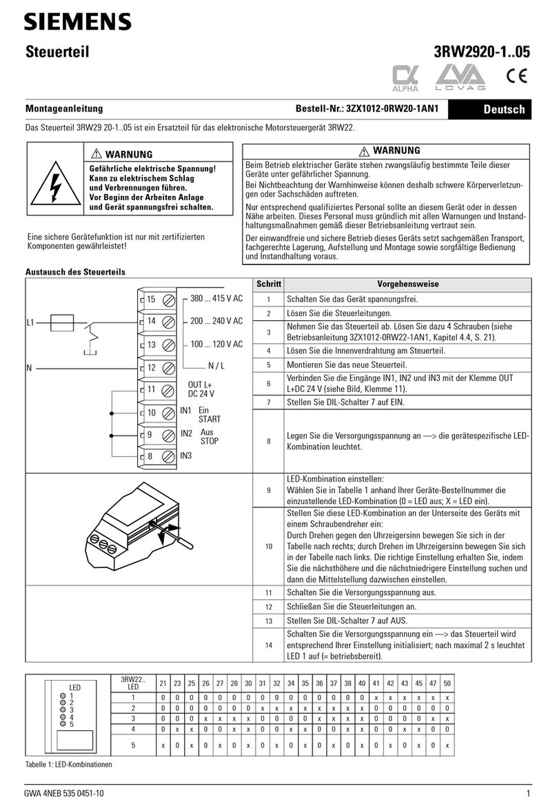
Siemens 3RW2920-1 05 Series Assembly instructions
