Negele DAC-341 User manual

Anderson Instrument Company - 156 Auriesville Road, Fultonville, NY 12072 - ph: 800-833-0081 fx: 518-922-8997
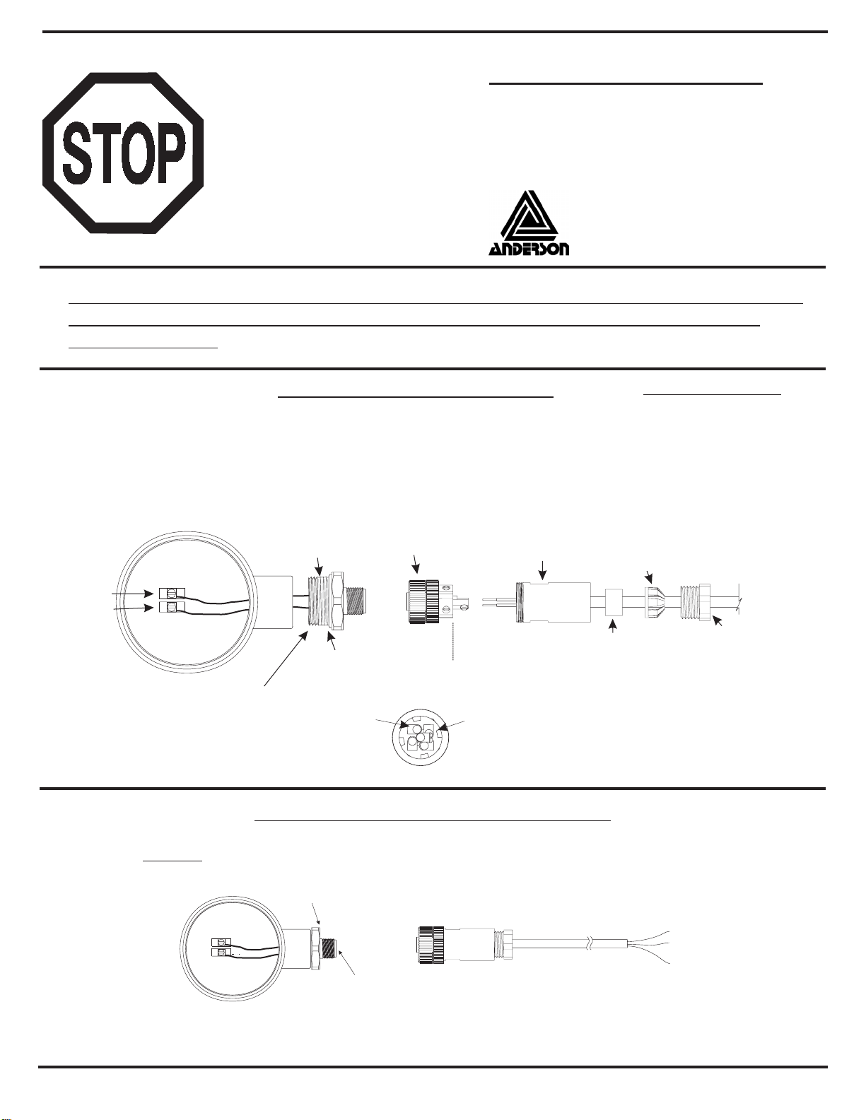
Installation DAC-341
Dimensioned Drawing DAC-341
Electrical Connection DAC-341
with M12 Plug-in
Installation
Attention: The maximum torque for
installation is 20Nm!
Table Overload Stability
range [bar] factor [bar]
0,2 25 5,0
0,4 15 6,0
1,0 10 10,0
2,0 7,5 15,0
4,0 6,25 25,0
10,0 4 40,0
20,0 2 40,0
with cable entry
Additional Products (for more informations: please see separate product informations)
Simulator
HSG-3
Alarm Relay
VGW-DC
Digital Display
DOH-VA
Processor Digital Display
PEM-DD

Initial Operation DAC-341
full adjustment
empty adjustment
1. Empty Adjustment
1.1 Level Measuring
• empty vessel completely
• connect ammeter into the current output loop
• the ammeter displays 4,0mA, the internal indicator, AZM displays 0,0%
In this case no adjustment is necessary
• in other case make the adjustment in the following way:
• press button "FF
FF
F" for at least 10 seconds, the indicator shows shortly "Stor",
the setting is done
• ammeter displays 4,0mA, the internal indicator AZM displays 0,0%
1.2 Process Pressure Measuring (relative / absolute)
• set the pressure to the wished value at 4mA
• connect ammeter into the current output loop
• the ammeter displays 4,0mA
in this case no adjustment is necessary
• in other case make the adjustment in the following way:
• press button "FF
FF
F" for at least 10 seconds. The indicator shows shortly "Stor",
the setting is done
• ammeter displays 4,0mA
2. Full Adjustment
2.1 Level Measuring
• fill vessel completely (heigth of vessel at least 25% of full range)
• connect ammeter into the current output loop
• the ammeter displays a value lower than 20 mA, e.g. 14 mA, the internal display AZM
displays a value lower than 100,0
• press button "++
++
+" or "--
--
-", until the ammeter displays 20mA and the internal indicator shows100%
• after about 20 seconds the settings are stored, "Stor" shortly appeares in the display
2.2 Process Pressure Measuring (relativ / absolute)
• set the pressure to high-value (at least 25% of full range)
• connect ammeter into the current output loop
• the ammeter displays 20,0mA, the internal indicator AZM displays the measured pressure
in bar. In this case no adjustment is necessary
• in other case make the adjustment in the following way:
• press button "++
++
+" or "--
--
-", until the ammeter displays 20mA
• after about 20 seconds the settings are stored, "Stor" shortly appeares in the display
3. Offset adjustment
• hold "FF
FF
F" pressed and modify with "++
++
+" or "--
--
-" the standard characteristic parallelly,
in this way offsets are compensated
• the settings are stored after 20s of the last adjustment, the indicator shows "Stor"
This function is needed very rarely.
4. Reset to standard settings
• press buttons "FF
FF
F", "++
++
+" and "--
--
-" togehter about 10 seconds. When the indicator
displays "rES", the standard settings are stored immediately.
Attention: All your settings will be deleted with this function . The pressure sensor
is set to the standard settings.
5. Switching the indicator (%, bar)
• by double-pressing the button "FF
FF
F" you can switch between the indication in bar and %
Connection
• plug in the optional indicator module AZM (helpful for setting)
• apply supply voltage (12...36V DC), see terminal label
• after a short segment test the indicator shows shortly 'dac', the program-version, 'abs' or 'rel' and the presetted range
• level in % (one digit after decimal point) or pressure in bar (two digits after decimal point) is indicated
• note at level measurement: 0-100% means 4-20mA; this range can be adjusted by the user. If the pressure is indicated in bar, the indicator
always shows the pressure measured at the measurement cell. In this kind the range of the indicator can't be adjusted!
Notes to Setting the Pressure Sensor
The standard setting of the DAC-341 is following: 0...100,0% of the measurement range (e.g. 0...400mbar) are corresponding to 4-20mA of the
current output. If it is necessary to change these settings for special measurement tasks, you have to do following:
offset adjustment
Anderson Instrument Company - 156 Auriesville Road, Fultonville, NY 12072 - ph: 800-833-0081 fx: 518-922-8997
2. Strip back 1-1/4” of outer sheathing, cut off any excess wires,
shield and ground. Strip off 1/4” insulation from remaining two
wires. It is not necessary or recommended to tin the wires.
1. Insert cable through Pressing Screw, Compression Ring,
Seal Grommet, and Sleeve as shown below.
CABLE REQUIREMENTS
2 conductor, stranded, 18-24 AWG,
shielded with ground.
4-8mm (0.16-0.31”) Cable Sheath OD
Shown With
Cap Removed
Red
Black
O-Ring
Thread sealing
tape applied.
3. Orient Connector end so that
center pin connecting screw is
horizontal facing right (see detail).
4. Wire LOOP+ (red) wire to top-right
terminal, and LOOP- (black) wire to
top-left terminal. No connection is made
to the center and bottom terminals.
5. Screw on the Sleeve. Hand-tighten only.
6. Press the Seal Grommet into the Sleeve and hand-
tighten the Pressing Screw.
7. Use a wrench to tighten the Pressing Screw another
3/4 turn. Do not over-tighten!
Connector End
Field Wireable Connector Assembly
LOOP +
LOOP -
Rev. 2.0 Doc 1142 Page 1 of 1
To install connector, simply line up key, press into
receptacle, and the retaining ringhand-tighten .
*In wet or corrosive environments it is recommended that the receptacle pins be coated with USDA
approved dielectric grease to minimize possibility of corrosion.
Field Wireable Connector (assembled)
Loop+(red) wire
Loop- (black) wire
Shield (clear or bare) wire
P/N: 42119B0000 (without cable)
P/N: 56623A0002
P/N: 5662400000
Receptacle
*Dielectric Grease
Retaining Ring
Pin 1 - Red
(+PWR 9-30 VDC)
Pin 2 - Black
(-PWR)
DETAIL
Sleeve
Seal
Grommet
Compression
Ring
Pressing Screw
-2 included choose one to accommodate cable OD
Transmitter
+ LOOP
- LOOP
Transmitter
Attaching The Connector To The Transmitter
Technical Bulletin
M12 Field Connector Wiring For
SL/SX/LD/LA/HA/RSP/SR/SV/DAC
and CT Transmitters
Revision 2.0 Document 1142
READ
THIS
FIRST Anderson Instrument Co., Inc.
156 Auriesville Road
Fultonville, NY 12072
Phone: 518-922-5315 or 800-833-0081
Fax: 518-922-8997 or 800-726-6733
The enclosed transmitter has been equipped with an M12 electrical connector.
The information below supersedes any wiring information provided in the
owners manual
Available upgrade kit # 56642A0001
includes: (1) 42119B0000 Connector
(1) 56623A0002 Receptacle
(1) 5662400000 Dielectric grease
To install the Receptacle tighten until
metal to metal contact is made. When
done properly the O-Ring should no
longer be visible.
Popular Industrial Equipment manuals by other brands


turck
turck IM12-CCM03 Series quick start guide

Carlisle
Carlisle ms 8132 0 Series Service manual

Emerson
Emerson Liebert eXL installation manual

Sumitomo
Sumitomo ASTERO BASA Maintenance manual

Prozone
Prozone PZ2-4 Thru PZ2-16 Installation guide and operation manual

Cooper Power Systems
Cooper Power Systems NOVA 15 Installation and operation instruction