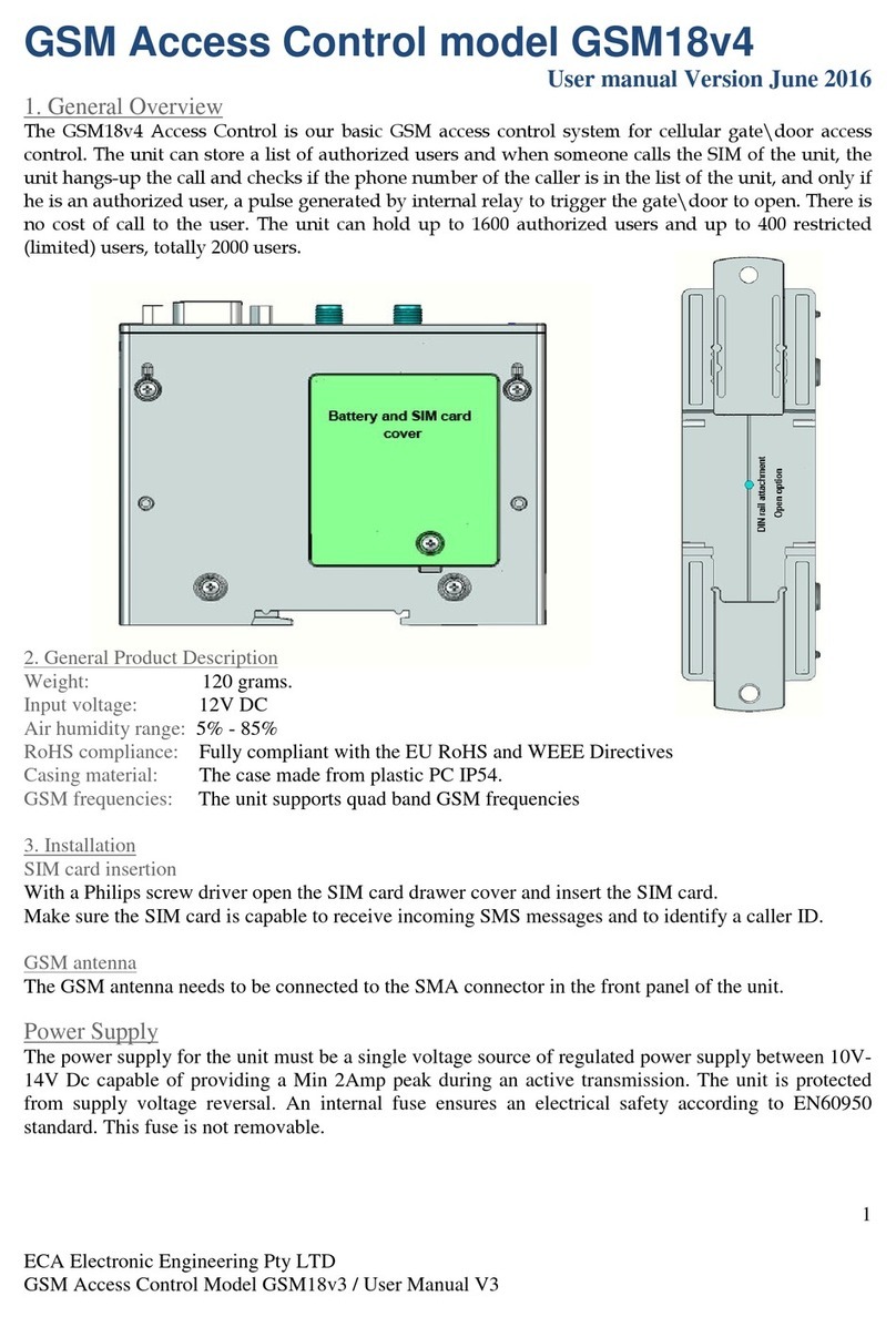
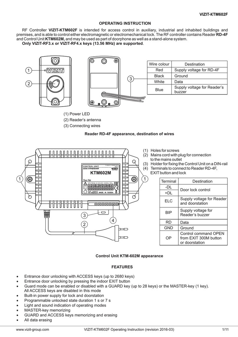
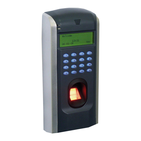
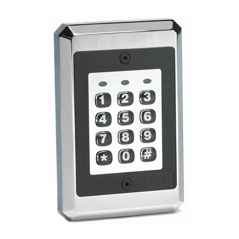
ECA GSM-18V4.1 User manual

1
ECA Electronic Engineering
Yearly & Weekly Timer
with GSM Access Control
ECA Models:
GSM-18V4.1
Access control only
GSM-18V4YT
Access control with Yearly Timer
ser Manual
Version 1
2019
Manufactured by ECA Electronic Engineering Pty LTD
Address: 76 -80 Levanswell Rd. Moorabbin Vic. 3189 Australia.
TEL: +61 3 95720535
Email: ecaelectronic@bigpond.com
www.gatesonsolar.com

2
ECA Electronic Engineering GSM Access control
Model : GSM18V4
1. GSM Access Control General Overview
This GSM access control system that can store up to 2000 users (phone numbers) and trigger the gate to open at no
cost of a call. When users call the SIM card of the unit the unit hangs-up the call and checks if the phone number
of the caller is in the system and triggers the gate only if the phone number is an authorized user.
Connection Diagram
To Push Button Input in the control
panel of the gate to trigger to open
Blue : Relay - Com.
White : Relay - N.O.
Gray : Negati e Input 1 :
Green: Negati e Input 2 :
BLACK
RED
:
www.gatesonsolar.com Tel: 03 95752535
GPS LED
GSM LED
12V - 18V Ac or DC
Normally Open
Normally Close
Relay output
selection
Jumper to select LEDs
Acti e ON or OFF
for solar application.
SIM
card
Ant.
STATUS of the gate : Open or Closed
ALERT by SMS each time the gate opens
1. Power
Make sure to insert the SIM card and connect the Antenna before you power up the unit.
Do not attach the unit’s antenna to any metal surface.
The unit can operate with voltage between 12V to 18V AC or DC using the Black and Red wires.
If DC power is used, the BLACK wire is the Negative and the RED wire is the Positive.
2. Memory
The unit can hold up to 1600 authorized users and up to 400 limited users total of 2000 users.
The authorized 2000 phone numbers can open the gate at any time and any day. The 400 restricted users
are limited to open the gate on certain days of the week and at a certain time intervals of the day.
The system will not answer any calls and hang-up on all incoming calls.
3. Output
The White and Blue wires are the internal relay’s connections; Normally Open (N.O.) & Com.
You can select Normally Close (N.C.) contact instead of the N.O. contact of the internal relay by the
external jumper in the unit. (See drawing above).
Note ! For solar applications
To reduce the current consumption of the unit, you can remove the jumper link on the right hand side in the
unit, to turn off the LEDs after the installation is complete. See diagram above.

3
_________________________________________________________
Please make sure that the mobile phone you are using to program this unit has its Caller ID ON.
Follow the instructions below to program the unit by SMS as per instructions below:
1. Adding and Deleting phone numbers
You can program and add up to 1600 phone numbers to be as normal users by sending SMS.
The example below shows how to add 2 phone numbers and delete one phone number by SMS:
9999AN.0417315263.0418655002.DE.0902345678
9999 Is the password (default password 9999)
“AN” Meaning: Add the following normal number(s).
“DE” Meaning: Delete the following normal number(s).
“.” The dot means end of a number.
Please Note: T
here is no need for the dot
“
.
“
at the end of the SMS command.
The maximum phone numbers are 5 phone numbers that can be added or deleted by one SMS command.
The unit should reply by SMS that says:
“Confirming: 0417315263.0418655002 added, 0902345678 deleted.”
Please Note
The unit disregards any phone numbers that were listed and could not be found in system memory of the unit.
2. Deleting ALL the phone numbers
To delete all the phone numbers, send the following SMS:
9999format
The unit will reply:
“THIS IS A WARNING. Do you wish to DELETE all the phone numbers? ”
If you wish to proceed, confirm by sending SMS saying: YES (must be in Capital letters)
The unit will send back SMS that says: “All phone numbers were deleted” to confirm.
Please Note
Ignoring the warning message and not replying “ YES ” within two minutes, will cause the unit to
disregard the last command and the phone numbers would be saved and not be deleted.
3. How to check the unit’s current internal clock
To check the local time, date and weekday in the system, send the following SMS:
9999clock
“9999” meaning: the password is 9999
“clock” meaning : current internal clock date and weekdays report.

4
The unit will reply by SMS that says: “The local time is: HH:MM / DD.MM.YYYY, Weekday.
4. Adding or Deleting “Special Users”
You can program up to 400 phone numbers to be as “SPECIAL USER”.
A “special user” is a Phone Number that has limited access on certain times of the day and is limited
to access the property on special days of the week only.
How to register special phone numbers and set a time zone for each phone number
a. The following SMS message is an example of how to allow unlimited number of entries with limited
time zone and limited days of the week for a special user with phone number 0418 317 452 :
9999AS.0418317452.0.0900.1700.127
“AS” meaning: Add Special number
“ 0” meaning: To allow unlimited numbers of entries.
“0900.1700” meaning: To limit entries between 9:00AM to 17:00PM.
“127” meaning: limiting entries for days of the week; Sundays Mondays & Saturdays.
The unit should reply by SMS that says:
“Confirming: The number 0418317452 allowed unlimited entries on Sundays Mondays
Saturdays between 9:00AM and 5:00PM”
b. The following SMS message is an example of how to allow limited number of entries with unlimited
times or days for a special number:
9999AS.0418317435.3.0900.1700.1234567
“AS” : Add Special number
“ 3” : To allow only 3 entries (this number can be any number between 1 – 99 )
“900.1700” : To limit the entries between 9:00AM to 17:00PM.
“1234567” : entries for all days of the week
Please Note
Please insert “0000.0000” for the time section if you do not want to limit the entries within any times
The unit should reply by SMS that says:
“Confirming: The number 0418317435 allowed 3 entries on all days of the week
between 9:00AM and 5:00PM”
c. The following SMS message is an example Special User without time limit but with limited days for
Sundays and Saturdays
9999AS.0418317435.3.0000.0000.17
The unit should reply by SMS that says:
“Confirming: The number 0418317435 is allowed 3 entries at any time on Sundays and
Saturdays.”

5
0 1 2 3 4 5
5.
How to choose the relay’s function; Pulse or Latch
You can choose one out of two following functions for the internal relay;
MOMENTARY (PULSE) or LATCH function (ON / OFF).
The factory default setting for the relay is a MOMENTARY function (with a 1 second PULSE).
You can choose the required setting by SMS command as follows:
I.
For Momentary Function Send SMS:
9999pulse01
II.
For Latch Function Send SMS:
9999latch
III.
For checking the current setting of the relay Send SMS:
9999function
The unit will reply accordingly to the above commands by SMS as follows:
I . Relay’s function is: Momentary Pulse of 1 second.
II . Relay’s function is set for Latch function.
III. If the unit is set for PULSE then: The relay function is set to Pulse of 1 second.
If the unit is set for LATCH then: The relay is set to Latch Function.
6. How to set the relay’s Pulse Time
The factory default time setting for the relay is a Pulse of 1 second.
You can choose and set the PULSE time interval of the relays by SMS as follows:
9999pulse_ _
The two under lines “ _ _ ” after the word “pulse” represent the time in seconds from 00 to 99
Use “00” for ½ a second pulse time.
“01” for 1 second pulse time. (Factory Default)
“02” for 2 second pulse time.
The unit will reply by SMS accordingly to the above as follows:
For Example, for SMS send: 9999pulse00
The replay will be: Relay’s function is Momentary Pulse of ½ a second.
7. How to check if the unit’s relay is ON or OFF
You can check the current status of unit’s relay by SMS command as follows:
9999relay
The unit will reply by SMS accordingly to current status of the relay:
If the relay is OFF the reply SMS would be: The relay is OFF
If the relay is ON the reply SMS would be: The relay is ON
8. How to check the GSM reception level
Send SMS:
9999reception
The reception level of the GSM network can be 0, 1, 2, 3, 4, or 5
The unit will check the reception of the GSM network in the area
and reply by SMS as follows: The reception is 5

6
9. Automatic Learning of all phone numbers
The unit can be set to learn up to 1600 Normal Users automatically while the users call the unit to
activate the relay. In this mode the unit checks the caller’s ID (the mobile phone number) of each
incoming call and registers it automatically in the system’s memory and at the same time triggers the
relay according to the chosen setting.
To activate the Automatic Learning Send SMS:
9999automatic
To cancel the Automatic Learning Send SMS:
9999manual
The unit will reply by SMS accordingly:
Automatic Learning mode is ON
or
Automatic Learning mode is OFF
10. How to check the number of users in the system
The system can be programmed with 1600 Normal Users and 400 Special Users
You can check the number of users in the system as follows:
Send SMS:
9999users
The unit will reply by SMS:
“There are XXXX normal users and XXX special users in the system”
11. How to LOCK / UNLOCK the system
The unit can be LOCKED, so that none of users can use the system and activate the relay.
To Lock send SMS:
9999lock
To Unlock send SMS:
9999unlock
The unit will reply by SMS accordingly:
“The unit is LOCKED” or “The unit is UNLOCKED”
12. HOLD COMMAND
The HOLD COMMAND enables you to overtake control of the system and keep the relay of the unit
active (ON) until cancellation command is received.
When the unit’s relay is in HOLD mode, the unit will not function to any other command until a
cancellation command is received.
When the HOLD COMMAND is active ON, the unit will send SMS to each user saying
“Hold Command is Active” each time the user will try to call and trigger the gate to open.
To activate the Hold Command send SMS as follows:
9999hold
The unit will reply by SMS: Hold Command is ON.
To cancel the Hold Command send SMS as follows:
9999release
The unit will reply by SMS: Hold Command is OFF.

7
13. OPEN TO ALL command
The unit can be programmed so that it will open the gate to ANY incoming call (without
checking if the caller is authorized user).
You can activate or cancel this function by SMS command as follows:
To activate the OPEN TO ALL command send SMS as follows:
9999open
The unit will reply by SMS: “Open To All : is ON.”
To cancel OPEN TO ALL command sends SMS as follows
9999close
The unit will reply by SMS: “Open To All : is OFF.”
14. How to set the unit to factory default settings
To set the unit to “Factory Default Settings” means the unit will delete all the phone numbers
and reset all the functions to factory default parameters as it was supplied initially.
To set the unit to Factory Default you need to send the following SMS command:
9999defualt
The unit will reply by SMS that says:
“THIS IS A WARNING from ECA Electronic Engineering. Do you wish to DELETE all the
phone numbers and set the unit to factory default ? “
To proceed and default the unit, you must confirm within 2 minutes
by SMS saying: YES (must be in Capital letters)
The unit will confirm by SMS that says: “The unit was set to factory default”.
15. How to change the Password
The factory default password is 9999 and it can be changed by sending the following SMS message:
9999passwordXXXX
The letters X XX X represent the new password.
The unit will confirm by SMS reply: “The new password is X X X X”
16. INPUT – 1 : Gate’s STATUS
This input can be used to check the status of the gate and see if the gate is OPEN or
CLOSE. This is done by connecting a magnetic read-switch to this input and to the ground.
If this input is connected to the Ground that means the GATE is CLOSED and if it is not
connected to ground (open circuit) in means the gate is OPEN.
To check the status of this input, send SMS command as follows:
9999status
The unit will reply by SMS accordingly:
If input 1 is connected to ground: The gate is closed.
If input 1 is open circuit: The gate is open.

8
17. How to customize the SMS message for INPUT – 1
You can customize the SMS message that the unit sends back when this input-1 is triggered to suit
different applications.
The default SMS messages send by the unit is:
When the input-1 is connected to ground: The gate is closed.
When the input-1 is open circuit: The gate is open.
You can program different messages by sending SMS message as follows:
9999RS
.
_ _ _ (Max 25 correctors) _ _ _
.
_ _ _ (Max 25 correctors)_ _ _
.
The following is an example for changing the messages to “The Alarm is ON” and “The Alarm is OFF”
9999RS.The Alarm is ON.The Alarm is OFF.
9999 Default password.
“RS” Meaning Status input-1
The Alarm is ON. Is the SMS reply message when the status input is connected to ground.
The Alarm is OFF. Is the SMS reply message when the status input is not connected to ground.
18. INPUT - 2 : ALERT
This input can be used to ALERT someone on his mobile phone each time input-2 is triggered.
This can be used as a DOOR BELL or ALERT the user each time the gate opens.
This can be done by connecting a push button as a door bell or a read-switch to trigger when the
gate opens and connect them to input-2 wire and ground. Each time this input is connected to the
ground (triggered), the unit will send SMS message as is set in the system.
The default message for this input is: “The gate was opened”.
You can program the phone number and different message by sending SMS message as follows:
9999AL
.
(Phone number )
.
_ _ _ (message send - Max 25 correctors)_ _ _
.
Following is an example for programming the user’s phone number and the message “Someone at the gate”
9999AL.0418347235.Someone at the gate.
9999 Default password.
“AL” Alert input
“0418347235” The users phone
“Someone at the gate” The SMS message when input-2 is triggered.

9
---------------------------------------------------------------------------------------------------------
Weekly Timer
This smart system will automatically set its local time, date and daylight savings changes as soon
as it is powered up. The weekly timer can be set to turn ON and OFF the internal relay on certain
days and at certain time intervals. For example; to turn ON the relay at 7:00AM and turn it OFF at
17:00PM on each Monday and Saturday.
1.
How to set the weekly timer
The following SMS message is an example of how to set the weekly timer:
Send SMS:
9999WT.0900.1700.127
“WT” : setting the weekly timer
“0900.1700” : to turn ON the relay between 9:00AM to 17:00PM.
“127” : days of the week; Sundays Mondays & Saturdays.
The day of the week can be 1~7 (1=Sunday, 2=Monday …..Friday = 6, 7=Saturday)
The unit will confirm by SMS that says:
“Confirming: Weekly Timer ON: Sunday, Monday, Saturday between 9:00AM and 17:00PM”
Please Note !
When the unit’s relay is ON (active) by the weekly timer, the unit will not respond to incoming calls
and will not trigger the relay for any user. Instead, the unit will send the following SMS message to
the user that made the call: "Your call was disregarded as the TIMER is ON at the moment"
2.
How to get the weekly timer settings report:
You can get the weekly timer’s current settings and events by sending the following SMS:
Send SMS:
9999WT.report
The unit will reply by SMS with all the time schedules in the system as in the example below:
“No events are recorded for the Weekly Timer”
Or for example:
“The Weekly Timer is ON: Sunday, Monday, Saturday, between 9:00AM and 17:00PM”
3.
How to clear the settings of Weekly Timer:
Send SMS:
9999WT.clear
The unit will delete the current settings of the weekly timer and reply by SMS message as follows:
“The Weekly Timer setting was deleted”

10
Yearly Timer
The yearly timer can be programmed to overtake control of the weekly timer and turn ON or OFF the
relay on certain days at certain times.
For example; to turn OFF the relay on 1
st
of September 2019 from 7:00AM till 13:00PM the next day.
This feature is very useful for setting public holidays and special events without the need of
accessing the unit on site.
Please Note ! This unit will automatically adjust the local time when daylight saving is due.
1. How to set the Yearly Timer
:
The following SMS message is an example of how to set the yearly timer:
SMS send:
9999YT.021219.0000.051219.2400.OFF
“9999” The default password 9999
“YT” setting the Yearly Timer
“021219” starting date is 2
nd
Dec. 2019
“0000” The time that the Yearly Timer will take control over the weekly timer is to be 00:00AM
“051219” Ending date 5
th
Dec. 2019
“2400” The time when the yearly timer finishes taking control over the weekly timer at 24:00PM
“OFF” The yearly timer will set the relay to OFF during the above day and interval of time.
The unit will reply by SMS that says:
“Confirming: Yearly Timer OFF: 02.12.19, 00:00AM till 05.12.19, 24:00PM”.
Another example:
SMS send:
9999YT.050119.0000.050119.2400.ON
The unit will reply by SMS that says:
“Confirming: Yearly Timer ON: 05.01.19, 00:00AM till 05.01.19, 24:00PM”.
Please Note
During the interval time when the relay is OFF (not active) the unit will respond to incoming calls of
the users and will trigger the relay according to the setting.
During the interval time when the relay is ON (active) the unit will not respond to incoming calls of
the users, but it will send the users that call the unit SMS message saying:
"Your call was disregarded as the TIMER is ON at the moment"

11
2. How to get all the Yearly Timer’s events that are registed in the unit
:
You can get the Yearly Timer events with the following SMS message:
Send SMS:
9999YT.report
The unit will reply back by SMS that says:
“No events are recorded for the Yearly Timer”
Or
“The yearly timer is set for:
21.05.18, 07:00AM till 21.05.18, 12:00PM, the system is ON
02.12.18, 00:00AM till 05.12.18, 24:00PM, the system is OFF.”
Please Note
1. The unit is limited to register up to 50 comments (events) for the yearly timer.
2. Each SMS reply from the unit will include two events only, accordingly, the report from the Yearly
Timer will be sent over by number of SMS messages as required.
3. Each event and setting will be automatically deleted from the unit’s memory, after the comment was
executed and finished.
3.
How to clear all the Yearly Timer’s settings and events :
Send SMS:
9999YT.clear
The unit will reply back by SMS that says:
“No events are recorded for the Yearly Timer”
All Rights Reserved to:
AUSTRALIA
Tel: +61 3 95720535
ecaelcetronic@bigpond.com
This manual suits for next models
1
Table of contents
Other ECA IP Access Controllers manuals
Popular IP Access Controllers manuals by other brands
Delta Controls
Delta Controls ASM-24 Installation & Application Guide
Dahua Technology
Dahua Technology ASC1202B-S user manual
2N
2N Access Unit installation manual
GeoVision
GeoVision GV-Reader 1251 installation guide
Roger
Roger MCT86M-IO-HR-CH operating manual

Gianni Industries
Gianni Industries GEM Easiprox+ Series installation guide
