manuals.online logo
Brands
  1. Home
  2. •
  3. Brands
  4. •
  5. Roger
  6. •
  7. IP Access Controllers
  8. •
  9. Roger MCX102-BRD User manual

Roger MCX102-BRD User manual

MCX102-BRD Installation Manual 2020-11-16
1/2
Roger Access Control System
MCX102-BRD Installation Manual
Firmware version: 1.0.4 and newer
Hardware version: 1.0
Document version: Rev. B
This document contains minimum information that is necessary for initial setup
and installation of the device. The detailed description of configuration
parameters and functionalities is specified in respective Operating Manual
available at www.roger.pl.
INTRODUCTION
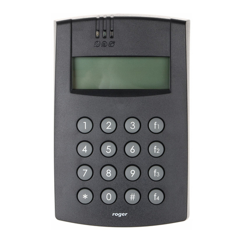
The expander is designed to operate in RACS 5 system as peripheral device
connected to RS485 bus of MC16 access controller. MCX102-BRD enables to
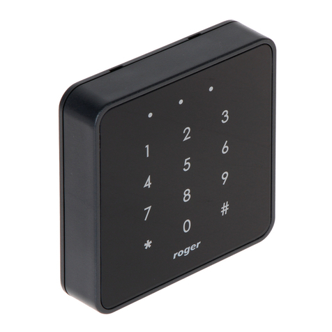
control single door by MC16 controller using two PRT series terminals or single
Wiegand terminal.
Factory new device is configured with default settings including ID=100 address.
Before connecting to MC16 controller, the device should be assigned with
unoccupied address in range of 100-115. Programming of other parameters
depends on the individual requirements and is not obligatory. Configuration of
the expander with RogerVDM requires RUD-1 interface.
CONFIGURATION WITH ROGERVDM PROGRAM
Fig. 1 Connection of the expander to RUD-1 interface
Programming procedure with RogerVDM software:
1. Connect the device to RUD-1 interface (fig. 1) and connect the RUD-1 to
computer’s USB port.
2. Start RogerVDM program, select MCX v1.x device, firmware version, RS485
communication channel and serial port with RUD-1 interface.
3. Click Connect, the program will establish connection and will automatically
display Configuration tab.
4. Enter unoccupied RS485 address in range of 100-115 and other settings
according to requirements of specific installation (e.g. NC type for IN1 input
according to fig. 5).
5. Click Send to Device to update the configuration.
6. Optionally make a backup by clicking Send to File… and saving settings to
file on disk.
MANUAL ADDRESSING
The RS485 address of expander configured with RogerVDM is a software
address. Alternatively hardware RS485 address can be configured with jumpers
and such address has higher priority than software address.
Fig. 2 Manual addressing of expander
Note: Each time the hardware RS485 address is modified the device must be
restarted
MEMORY RESET
Memory reset procedure restores factory default settings including ID=100
software address.
Expander memory reset procedure:
1. Remove all connections from A, B, CLK and DTA terminals.
2. Place jumper on 64 contacts and restart device with RST button on device
board or by switching supply off and on.
3. Remove jumper from 64 contacts when LED STAT (red), LED OPN and LED
SYS are ON.
4. LED OPN and LED SYS will switch off and device shall restart automatically
with factory default settings.
FIRMWARE UPDATE
The update requires connection of expander to computer with RUD-1 interface
(fig. 1) and starting RogerISP software. The latest firmware file is available at
www.roger.pl.
Expander firmware update procedure:
1. Connect the device to RUD-1 interface (fig. 1) and connect the RUD-1 to
computer’s USB port.
2. Put jumper on FDM contacts
3. Restart device with RST button on device board or by switching supply off
and on.
4. Start RogerISP software.
5. Select serial port emulated by RUD-1 interface and the option USB-RS485
Converter.
6. Select firmware file (*.hex), click Program and follow instructions on screen.
7. Once the firmware is uploaded remove the FDM jumper and restart the
device.
8. Start Memory reset procedure.
APPENDIX
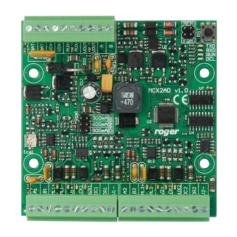
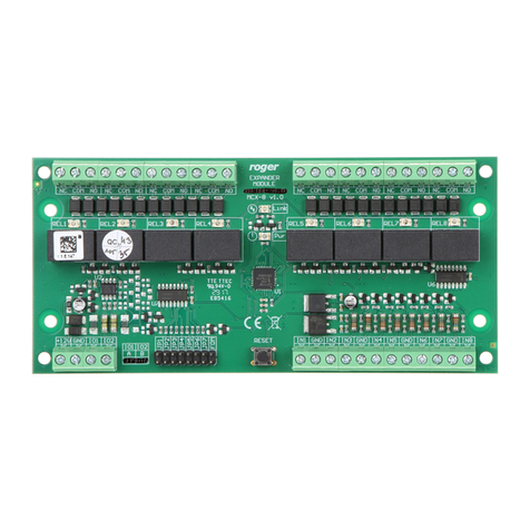
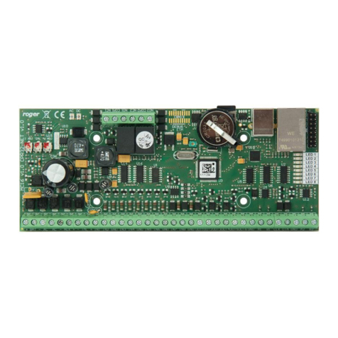
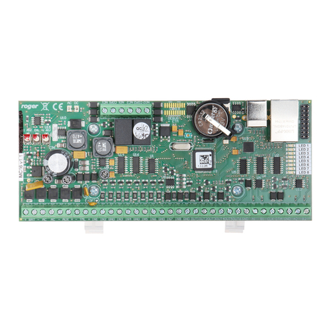
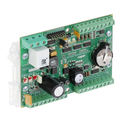
Fig. 3 MCX2-BRD expander
Table 1. Screw terminals
Name
Description
+12V
12VDC power supply
GND
Ground
IN1, IN2
Input lines
OUT1
15VDC/150mA transistor output line
A, B
R485 bus
CLK, DTA
RACS CLK/DTA bus
NO, COM, NC
Relay (REL1) 30V/1,5A DC/AC output
Table 2. LED indicators
Indicator
Colour
Integral functions
STA
Red/ green
Current arming mode of Alarm Zone
(armed/disarmed)
OPN
Green
Door unlocked
SYS
Orange
Various signalling functions including errors
LINK
Green
Data transmission on RS485 bus
MCX102-BRD Installation Manual 2020-11-16
2/2
Fig. 4 Connection of readers and expanders to MC16 access controller
Table 3. Specification
Supply voltage
Nominal 12VDC, min./max. range 10-15VDC
Current consumption
(average)
40mA (when relay off)
Inputs
Eight (IN1..IN8) NO/NC inputs, triggering level
app. 3.5V
Relay output
Single (REL1) relay output with isolated NO/NC
contact, 30V/1.5A max load
Transistor output
Single (OUT1) transistor output, max load
15VDC/150mA
Distances
Up to 1200 m between controller and expander
(RS485)
Up to 150m between expander and PRT or
Wiegand terminals
IP Code
IP20
Environmental class
(according to EN 50133-1)
Class I, indoor general conditions, temperature:
+5°C to +40°C, relative humidity: 10 to 95% (no
condensation)
Dimensions W x S x G
80 x 54 x 20 mm
Weight
50g
Certificates
CE
Fig. 5 Typical door control with PRT readers
Fig. 6 Typical door control with Wiegand reader
Notes:
Any 12VDC/1.5A buffer power supply unit can be used for expander and door
devices.
MCX102-BRD cannot charge battery therefore backup power supply must be
ensured on the level of PSU.
Diagrams include doors with electric strikes. In case of electromagnetic lock,
the NC terminal of relay is used instead of NO terminal.
Diagram in fig. 6 includes exit button. In case of read-in/out doors it can be
used for emergency door opening.
This symbol placed on a product or packaging indicates that the
product should not be disposed of with other wastes as this may
have a negative impact on the environment and health. The user is
obliged to deliver equipment to the designated collection points of
electric and electronic waste. For detailed information on recycling,
contact your local authorities, waste disposal company or point of
purchase. Separate collection and recycling of this type of waste
contributes to the protection of the natural resources and is safe to
health and the environment. Weight of the equipment is specified in
the document.
Contact:
Roger Sp. z o. o. sp. k.
82-400 Sztum
Gościszewo 59
Tel.: +48 55 272 0132
Fax: +48 55 272 0133
Tech. support: +48 55 267 0126
E-mail: support@roger.pl
Web: www.roger.pl

Other manuals for MCX102-BRD

1

Other Roger IP Access Controllers manuals

Roger MCT84M-BK-QB User manual

Roger

Roger MCT84M-BK-QB User manual

Roger MCX402-BRD User manual

Roger

Roger MCX402-BRD User manual

Roger EDGE1 Series Product manual

Roger

Roger EDGE1 Series Product manual

Roger MCT86M-IO-CH-HR User manual

Roger

Roger MCT86M-IO-CH-HR User manual

Roger MCT80M-BLE User manual

Roger

Roger MCT80M-BLE User manual

Roger MCX402-BRD User manual

Roger

Roger MCX402-BRD User manual

Roger MCT88M-IO User manual

Roger

Roger MCT88M-IO User manual

Roger MC16-SVC User manual

Roger

Roger MC16-SVC User manual

Roger MCT82M-IO-HR-F User manual

Roger

Roger MCT82M-IO-HR-F User manual

Roger MC16-PAC-EX/ST-2-KIT User manual

Roger

Roger MC16-PAC-EX/ST-2-KIT User manual

Roger MC16-PAC-3-KIT User manual

Roger

Roger MC16-PAC-3-KIT User manual

Roger MCT68ME-IO User manual

Roger

Roger MCT68ME-IO User manual

Roger PR201 Assembly instructions

Roger

Roger PR201 Assembly instructions

Roger MCT88M-IO User manual

Roger

Roger MCT88M-IO User manual

Roger MCT68ME-IO-I User manual

Roger

Roger MCT68ME-IO-I User manual

Roger PRT12MF-DES User manual

Roger

Roger PRT12MF-DES User manual

Roger PR622 User manual

Roger

Roger PR622 User manual

Roger MCX2D User manual

Roger

Roger MCX2D User manual

Roger PR402DR-BRD User manual

Roger

Roger PR402DR-BRD User manual

Roger PR402 User guide

Roger

Roger PR402 User guide

Roger PR302 User manual

Roger

Roger PR302 User manual

Roger CEB12 User manual

Roger

Roger CEB12 User manual

Roger RFT1000 User manual

Roger

Roger RFT1000 User manual

Roger MC16-PAC-1-KIT User manual

Roger

Roger MC16-PAC-1-KIT User manual

Popular IP Access Controllers manuals by other brands

IBA X6 instruction manual

IBA

IBA X6 instruction manual

Matrix COSEC VEGA FAX Quick installation guide

Matrix

Matrix COSEC VEGA FAX Quick installation guide

ACS EXP-06E Installation and operation instructions

ACS

ACS EXP-06E Installation and operation instructions

Wasp B2000 user manual

Wasp

Wasp B2000 user manual

Supra TRACcess BT Smart Device manual

Supra

Supra TRACcess BT Smart Device manual

NUUO SCB-C31A POS user manual

NUUO

NUUO SCB-C31A POS user manual

Engineering Solutions ACCESSOR 4000+ owner's manual

Engineering Solutions

Engineering Solutions ACCESSOR 4000+ owner's manual

ZKTeco SA32-E user manual

ZKTeco

ZKTeco SA32-E user manual

Select Engineered Systems SG2CL Installer's guide

Select Engineered Systems

Select Engineered Systems SG2CL Installer's guide

IDTECK Star iCON100 Quick install guide

IDTECK

IDTECK Star iCON100 Quick install guide

Dahua Technology ASI1212D Quick install guide

Dahua Technology

Dahua Technology ASI1212D Quick install guide

HIK VISION DS-K5603-Z quick start guide

HIK VISION

HIK VISION DS-K5603-Z quick start guide

HIK VISION DS-K4T100 manual

HIK VISION

HIK VISION DS-K4T100 manual

UNIONCOMMUNITY Virdi 4000 user guide

UNIONCOMMUNITY

UNIONCOMMUNITY Virdi 4000 user guide

HIK VISION DS-K1T605 Series user manual

HIK VISION

HIK VISION DS-K1T605 Series user manual

UNIONCOMMUNITY Virdi AC-2100 user guide

UNIONCOMMUNITY

UNIONCOMMUNITY Virdi AC-2100 user guide

Delta DS-K1T804MF-1 user manual

Delta

Delta DS-K1T804MF-1 user manual

HIK VISION DS-K281 Series user manual

HIK VISION

HIK VISION DS-K281 Series user manual

manuals.online logo
manuals.online logoBrands
  • About & Mission
  • Contact us

  • Privacy Policy
  • Terms and Conditions

Copyright 2025 Manuals.Online. All Rights Reserved.