ECB BIG TUBE BH39SY User manual

.© Copyright –ECB Pty Ltd –2018 1
BH39SY
FITTING INSTRUCTIONS
RODEO RA7 03/07on & ISUZU D-MAX
BIG TUBE™PROTECTION BAR WITH 9000LB
WARN WINCH MOUNTING BRACKET
VEHICLE FRONTAL PROTECTION SYSTEM (VFPS)
FOR AIR BAG AND ADR COMPLIANT VEHICLES
Check installation hardware before commencing.
1. Lift bonnet.
2. Remove grille. Two plastic clips and two 10mm head bolts along top, one PK self-taper just below Holden badge
and two PK self-tapers in bottom corners. Gently lift grille and release two plastics clips into bumper cover
underneath (from rear of grille) See figure 1
3. Remove bumper cover. Three plastic clips along top under grille area, one 10mm head self-taper and one plastic
clip (each side). Two plastic clips at bottom. Disconnect lights on removal if fitted.
4. Remove cross member from front of chassis. Four 14mm head bolts. See figure 2. Remove two bumper cover
lower support brackets from vehicle. One 10mm head bolt (each side).
5. Remove chassis protection plate, four 14mm head bolts.
6. Attach ECB steel mounting brackets (supplied) to front of chassis. Use four M10 x 40 x 1.25 bolts/washers
(supplied). See figures 3 and 4. FINGER TIGHTEN ONLY.
7. Centre and level steel mounting brackets on vehicle. Ensure sufficient distance apart for protection bar to mount
on inside of steel mounting brackets. Check protection bar measurement. Use two M10 x 35 x1.25
bolts/washers (supplied) in lower mount holes. TIGHTEN steel mounting brackets in position two.
NOTE: Two extra 3/8 flat washers are supplied for spacers between lower welded bracket on steel mount and
chassis if required.
NOTE: Once M10 x 40 bolts are tight, fit one M10 nut (supplied) over each bolt TIGHTEN. See figure 5
8. Place winch mounting bracket (supplied) on top of plates welded to steel mounting bracket. Use 7/16 x 1 ½ bolts,
nuts and washers (supplied). Centralise on vehicle and TIGHTEN ALL BOLTS/NUTS.
9. Attach roller fairlead to winch mounting bracket. Use original 7/16 x 1 winch bolt, nut and washer. Feed 7/16 x 1
bolt, washer from inside. Attach nut and washer on outside. FINGER TIGHTEN ONLY
10. Attach winch to winch mounting bracket, feed winch cable through roller fairlead as installing. Use original
winch 3/8 x 1 ¼ bolts and spring washer with 3/8 flat washers (supplied). TIGHTEN WINCH IN POSITION.
See figure 6.
11. Attach control box bracket (supplied) to control box. Place ¼ flat washer (supplied) over studs, then control box
bracket, then ¼ flat washer (supplied). Use original nuts. See figure 7.
NOTE: For XD9000 Warn: attach two ¼ nuts and washers on bolts before connecting into rear holes on mount.
XP9000 Warn uses side holes and sits with plug to front.
REPLACES: 11.03.10
REVISED: 17.01.18

.© Copyright –ECB Pty Ltd –2018 2
12. Connect all winch wiring. Ensure wiring is clear of winch wire rope and routed in such a manner to avoid damage
from heat and or sharp edges. Use 200mm long zip ties (supplied).
NOTE: Crimps on wiring need to be flat side up See figure 8.
13. Position control box on top of winch. Do not bolt on at this stage. Check wiring to ensure snug fitment.
See figure 9.
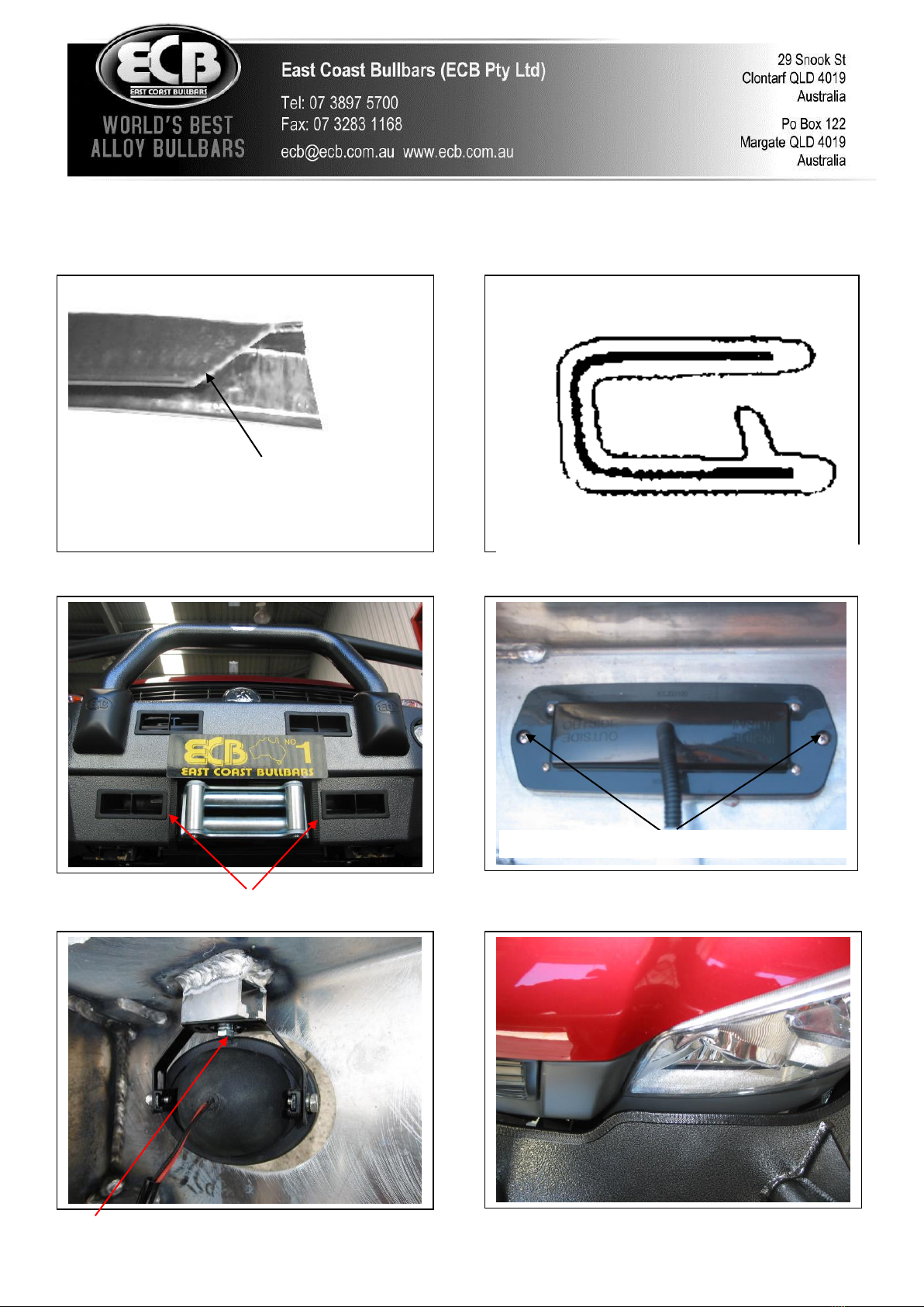
14. Mask and cut bumper using a jigsaw, see figures 10, 11. Clean edges. Fit 3mm clip lock to top cut edge.
NOTE: What you leave after cut is the finished edge.
15. Refit bumper as per reverse of step 3.
16. With a10mm drill, using steel mount as a guide, from rear of bumper drill hole thru bottom edge of bumper. Treat
all exposed metal with rust inhibitor or similar. Use original plastic clips to secure bumper.
17. Feed wiring through hole above original fog lamps or blanks. Splice ECB indicator/park light and fog light
wiring into original wiring loome. Use cable locks (supplied). Do not reconnect original fog lamps if fitted.
NOTE: If original fog lamps not fitted, an accessory switch and wiring will be required.
18. Attach 6mm clip lock trim (supplied) to top of ECB protection bar. Attach 6mm clip lock trim (supplied) to skirt.
NOTE: Trim off lower edge so trim will sit to end of protection bar. See figures 12, 13, 14 and 15. NOTE: Seal
any exposed edges of trim with silicone or similar to avoid corrosion of inner steel.
19. Fit ECB LED indicator / park lights (supplied) into protection bar as per instructions supplied with the LED
indicator kit. NOTE: Ensure park light is to outside. See figure 16.
20. Attach ECB fog lights to protection bar. Place M6 x 20 bolts, spring washers (supplied) through light mount
from inside and attach nut to top. Slide assembly into light mount in Protection bar and centralize light to hole.
See figure 17. TIGHTEN ALL BOLTS FIRM ONLY. Do not fit fog light trims at this stage.
21. Remove air vents from protection bar to allow access for bolts and nuts.
22. Move control box to rear of bumper above cable drum of the winch to allow access to mount bolts.
23. Attach protection bar to inside of steel mounting brackets using three ½ x 1 ½ bolts flat and spring washers and
nuts (each side) (supplied). Access to bolts are from outside corners of bar for front two bolts and between inner
guard and bumper for rear bolt
24. Align protection bar with approximately 10mm clearance off grille and 3-5mm from contacting top of bumper
under headlights. See figures 18, 19 & 20.
25. Re align and fit winch control box mount to underside rear of winch frame using two ¼ x 1 bolts, washers and
nyloc nuts (supplied). Ensure winch cables clear all sharp edges and possible hot surfaces.
26. Refit under body protection plate using original rear 2 bolts and bolts previously fitted to bottom of mount.
27. TIGHTEN ALL BOLTS/NUTS.
28. Connect ECB indicator/park light. Secure to original wiring with zip ties (supplied). Ensure wiring is routed in
such a manner to avoid any sharp edges etc. CHECK OPERATION
.© Copyright –ECB Pty Ltd –2018 3
29. Connect fog lights. Secure to original wiring with zip ties (supplied). Ensure wiring is routed in such a
manner to avoid any sharp edges etc. CHECK OPERATION. Aim with low beam, TIGHTEN IN POSITION.
Fit ECB fog light trims (supplied) to protection bar, wider part of trim to inside.
30. Refit air vents to protection bar. NOTE: Upper drivers side air vent must be trimmed down to avoid fouling on
winch control box. Place top vents upside down to maximise air flow to radiators.
ENSURE NUMBER PLATE IS CLEARLY VISABLE
Note: When fitting/refitting the licence plate to the vehicle, ensure there is no obstruction to licence plate vision in
accordance with local authorities. If required relocate licence plate to an alternate location.
Further VFPS Notes:
a) Do not attach VFPS to the vehicle using anchorages not intended for this purpose (e.g. engine mounting bolts).
b) Do not use this product for any vehicle make or model, other than those specified by the VFPS manufacturer.
c) Do not remove the plaque or label from the VFPS.
d) Do not modify the structure of the VFPS in any way.
e) No accessory or fitment should project forward of the VFPS forward profile.
f) ENSURE THESE INSTRUCTIONS ARE LEFT WITH VEHICLE OWNER AND/OR OPERATOR.
IMPORTANT INFORMATION
Periodically check bolts and nuts for correct tightness, especially if travelling on rough roads
FITTING KIT
2 –Steel mounting brackets.
2 –M6 flat washers
1 –Winch mounting bracket.
2 –M6 nuts and spring washers
1 –Control box bracket.
1 –ECB LED Indicator / Park light kit
4 –M10 x 40 x 1.25 bolts/nuts.
2 –ECB Fog lamps
2 –M10 x 35 x 1.25 bolts.
2 –Fog lamp surrounds
10 –10mm flat washers.
1 –800mm length 3mm black clip lock.
6 –10mm spring washers.
2 –200mm lengths 6mm clip lock
6 –½ x 1 ½ bolts/nuts.
1 –2200mm length 6mm clip lock.
12 –½ flat washers.
10 –Cable locks.
6 –½ spring washers.
8 –¼ flat washers.
6 –7/16 x 1 ½ bolts/nuts.
2 –¼ x 1 bolts/nuts.
12 –7/16 flat washers.
2 –¼ nyloc nuts.
6 –7/16 spring washers.
4 - 150mm zip ties
4 –3/8 flat washers.
4 –200mm zip ties.
2 –M6 X 20 bolts

.© Copyright –ECB Pty Ltd –2018 4
Figure 2
Figure 3 –Passenger side shown
Figure 5
M10 lock nut
Figure 1
M10 x 40 bolt
Cross Member
Figure 4 –Drivers side shown
Figure 6

.© Copyright –ECB Pty Ltd –2018 5
Figure 8 –Winch out of vehicle for photo only
Figure 7
Figure 10
Figure 9 –XP 9000 shown
Attach 6mm clip lock trim to edge
of channel
.© Copyright –ECB Pty Ltd –2018 6
Figure 15
Figure 11 –Bumper after cut
Figure 12
Figure 14
Top
Black Clip Lock Trim
Attach 6mm clip lock trim
Stainless steel self-tappers
Figure 16
Figure 17
M6 bolt
Figure 18
Trim lower
edge on an
angle
Figure 13

.© Copyright –ECB Pty Ltd –2018 7
Figure 19 –Front view shown
Figure 20 –Side view shown

.© Copyright –ECB Pty Ltd –2018 8
We value your comments
Dear Fitter,
ECB would like to know how you went with the installation of this product. We value your comment and may need to
contact you to clarify some details so please complete your contact details clearly.
We would appreciate if you could complete as many of the following details as possible.
Your Name:
Your contact No.
Product Part No.
Product Invoice No.
Product Description:
Make, model, and year of vehicle:
Product Work Order No.
Company your from/Company product purchased from:
Date of Fitment: ____/____/____
Yes No
Was the fitting hardware supplied complete?
If no what was not supplied
______________________________________________________________________________________
______________________________________________________________________________________
______________________________________________________________________________________
Yes No
Did the installation go well?
Please provide comments
______________________________________________________________________________________
______________________________________________________________________________________
______________________________________________________________________________________
______________________________________________________________________________________
Please draw diagrams if you need to.
Post to Fax to
Reply Paid 122 (07) 3283 1168
PO Box 122
Margate QLD 4019
.© Copyright –ECB Pty Ltd –2018 9
DESPATCH CHECKLIST
BH39SY
ICZBKCH39 *ICZBKCH39*
Work Order #
Finish:
Transport:
Due Date:
O2 –Steel mounting brackets.
O1 –Winch mounting bracket.
O1 –Control box bracket.
O1 –Bolt Kit.
O1 –ECB LED Indicator / Park light kit.
O2 –ECB fog lamps.
O2 –ECB fog lamp surrounds.
O1 –800mm length 3mm clip lock
O2 –200mm lengths 6mm clip lock
O1 –2200mm length 6mm clip lock
O2 –ECB overriders –Fitted to bar.
O4 –6mm air scoops –Fitted to bar.
All parts checked and completed by:
Nut and bolts: __________________________Date__/__/__
Order control: __________________________Date__/__/__
Final wrap check: __________________________Date__/__/__
Is this product “the best it can be”Yes ______/______
Wrapper’s initials / Checker initials
If NO fix before continuing
See other side of
this page for
photos of all
mounts

.© Copyright –ECB Pty Ltd –2018 10
Other ECB Automobile Accessories manuals


