ECB BIG TUBE BT128SY User manual

BT128SY REPLACES: 00.00.00
REVISED: 04.10.11
FITTING INSTRUCTIONS
HILUX 09/11on 2WD / 4WD BIG TUBE™ PROTECTION BAR
WITH 9000LB WARN WINCH FITMENT
VEHICLE FRONTAL PROTECTION SYSTEM (VFPS)
FOR AIR BAG & ADR COMPLIANT VEHICLES
Check installation hardware before commencing.
1. Lift bonnet
2. Remove grille, two plastic clips and two PK self-tappers along top, pull grille forward at top enough to access
and release five fixed clips along bottom inside of grille.
3. Remove bumper cover, three plastic clips along top (grille area), one plastic clip (each side) at bumper cover top
side returns, four 10mm head self-tapper on inner guard (each side), three plastic clips along bottom of bumper
cover. Pull bumper cover outward at sides to release off clips.
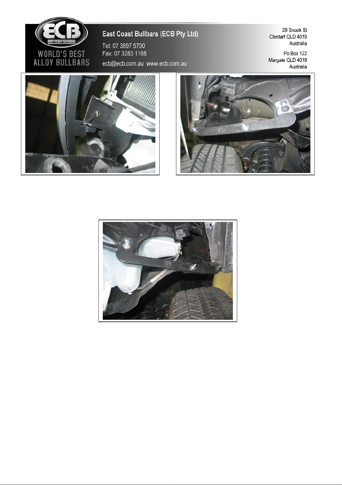
4. Remove steel chassis cross member from front of chassis, four 14mm nuts. See figure 1.
On 4WD models:Remove two plastic clips from plastic under body guard (each side).
5. On 4WD models trim plastic air deflectors at top of cross member. See figure 2.
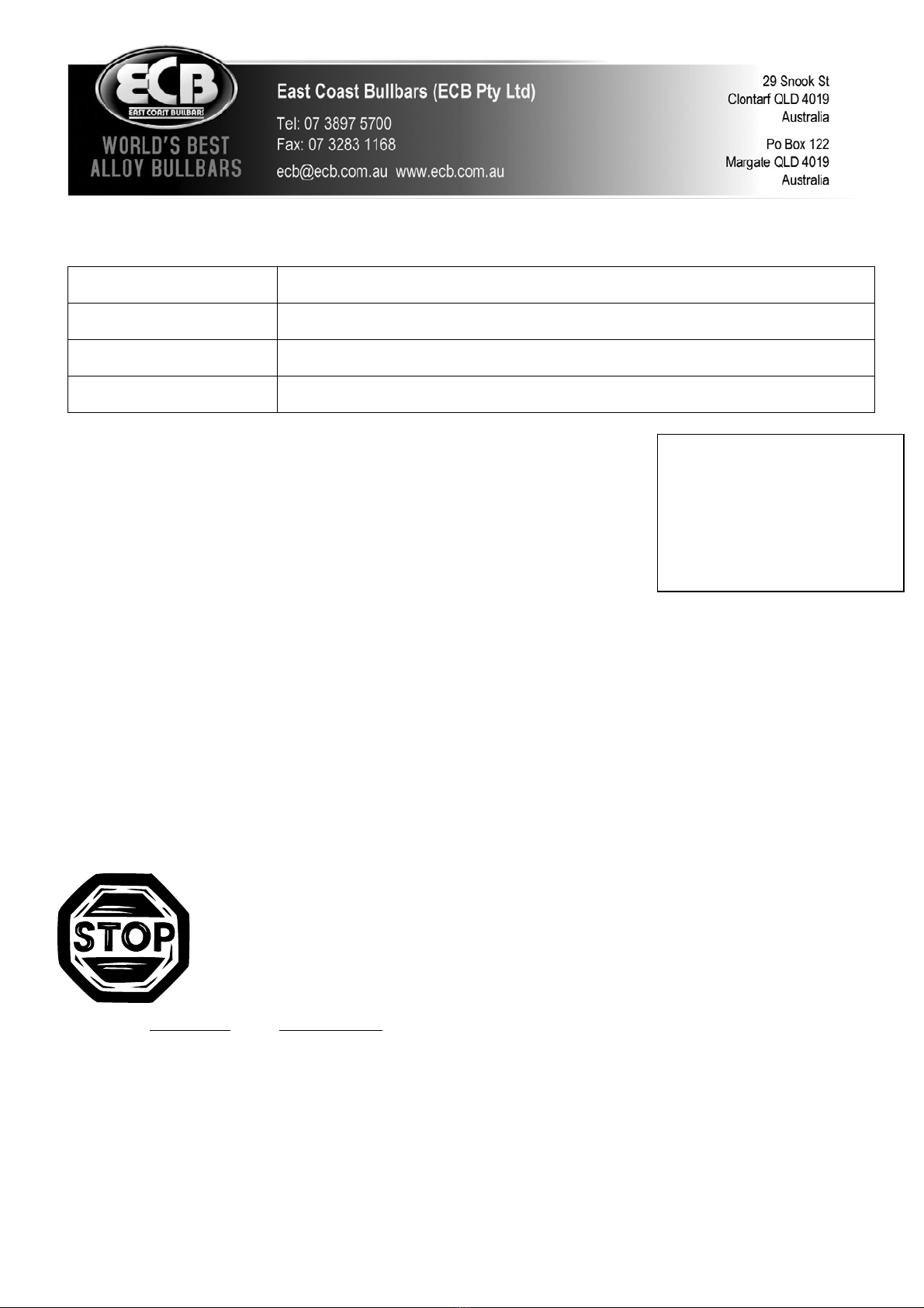
6. Remove four bumper cover support brackets from vehicle. See figure 3.
7. Remove headlight / indicator assemblies from vehicle. Three 10mm head self-tappers and one 10mm head bolt.
Disconnect wiring as removing. See figure 4.
8. Remove plastic bumper cover support brackets from bottom of headlights. Two PK screws(per light) See figure5
9. Remove plastic bumper cover side supports from each guard. One 10mm head self-tapper. See figure 6.
10. Connect ECB Quick click indicator / park light wiring harness (supplied) to original wiring loom. Refit headlight
/ indicator assemblies connecting to the other side of the ECB wiring harness. Run ECB wiring harness out from
under headlight ensuring it is clear of all sharp edges and pinch points.
11. Remove steel under guard, four 12mm head bolts. Remove two cross member supports from chassis. See figure
7. Five 14mm head bolts (per support).
12. Rotate gearbox housing on winch if necessary. See figure 8. Remove ten allen head bolts – move housing out
just off spline to rotate.
13. Connect control box cables to winch and sit control box on top of winch.
14. Place winch mounting bracket (supplied) on trolley jack or similar, sit winch and control box in winch mount
with winch slightly toward passenger side. DO NOT BOLT winch to winch mount. See figure 9.
15. Jack up onto chassis just forward of chassis studs – once aligned push back onto chassis studs. Use original nuts
for chassis studs. FINGER TIGHTEN ONLY. See figures 10 and 11.
.© Copyright – ECB Pty Ltd – 2012 1

.© Copyright – ECB Pty Ltd – 2012 2
16. Refit two original cross member supports over winch mount. Use four M10 x 35 x 1.25 bolts, flat and spring
washers (supplied) for winch mount. See figure 12. Ensure 10mm holes on winch mount are aligned with middle
chassis hole. TIGHTEN FOUR ORIGINAL NUTS ON STUDS FIRST – THEN TIGHTEN ALL CROSS
MEMBER BOLTS.
17. Refit steel under guard.
18. Slide winch into position, insert top winch captive nuts, then bolt winch in place with top bolts only. Use 3/8 x
1¼ winch bolts with flat and spring washers (supplied). FINGER TIGHTEN ONLY. NOTE: Ensure any air
conditioning lines etc are clear of winch.
19. Fit control box bracket (supplied) to inside of winch mount. Use M8 x 30 bolts, nuts and washers (supplied)
FINGER TIGHTEN ONLY. NOTE: Attach motor earth lead to one of M8 x 30 bolts – Ensure good earth
contact.
20. Bolt control box to control box bracket. NOTE: Standard control box will require the 95x 50x6 spacer plate to
be positioned between control box and control box bracket. Use original nuts with four ¼ flat washers (supplied)
for each side of control box bracket and spacer. TIGHTEN ALL BOLTS AND NUTS Ensure all winch cables
are positioned to avoid any rubbing etc.
21. Centralise winch ensuring all clearances around winch are sufficient, insert lower captive nuts into winch. Align
lower captive nuts, then TIGHTEN top winch bolts.
22. Feed winch cable through winch mount. Fit roller fairlead over winch cable and bolt to winch. Use 3/8 x 1½
winch bolts with flat and spring washers (supplied). Align roller fairlead. TIGHTEN BOLTS.
23. Wire winch to battery as per winch instructions. Check winch for correct operation.
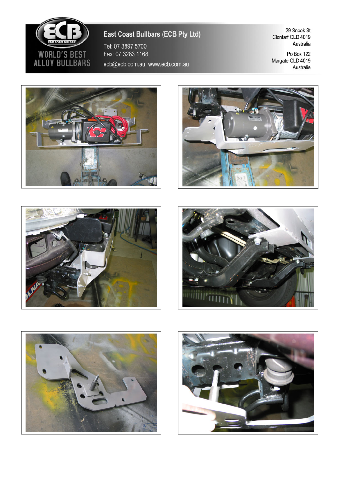
24. Place 3/8 x 4 bolt with flat washer (supplied) through 10mm hole in steel mounting bracket. Slide 52mm long
pipe chassis spacer (supplied) over bolt. See figure 13. Fit steel mounting bracket to chassis with pipe spacer
into middle chassis hole and insert through winch mount. See figure 14. Use 3/8 nut, flat and spring washers
(supplied) FINGER TIGHTEN ONLY.
25. Fit M12 x 35 x 1.25 bolt, flat and spring washers (supplied) and M8 x 30 bolt, flat and spring washers (supplied)
into captive nuts in chassis. FINGER TIGHTEN ONLY. See figure 15. Fit 3/8 x 1½ bolts, nuts and washers
(supplied) from winch mount to steel mounting brackets. See figure 16.
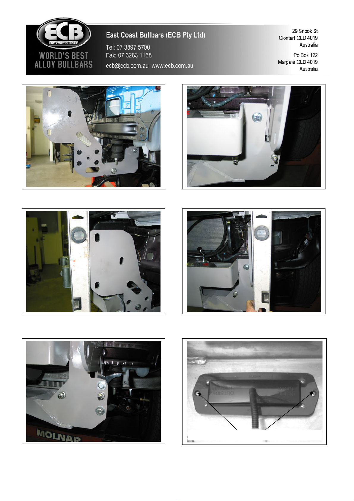
26. Tighten M12 x 35 x 1.25 bolts firm only. Level steel mounting brackets off front edge. See figure 17.
TIGHTEN ALL BOLTS / NUTS (as per the below sequence) ensuring steel mounting brackets remain
centralised with vehicle and are correct distance apart for alloy protection bar to mount on outside of steel
mounting brackets.
Mount bolt tighten sequence:
a) TIGHTEN M12 x 35 bolts first.
b) TIGHTEN 3/8 x 4 bolt/nut FIRM ONLY
c) Align steel mounting brackets level at sides and with enough distance apart for protection bar to mount on
outside of steel mounting brackets. See figure 18. TIP: Tighten 3/8x 1½ bolt/nut firm only then tap mounts into
position.
d) TIGHTEN 3/8 x 1 ½ bolts and nuts from winch mount to steel mounting bracket.
e) TIGHTEN 3/8 x 4 bolts/nuts.
f) TIGHTEN M8 x 30 bolts.
27. Use four 3/8 x 1¼ bolts, nuts and washers (supplied) for extra holes in front of chassis. See figure 19.
TIGHTEN.

.© Copyright – ECB Pty Ltd – 2012 3
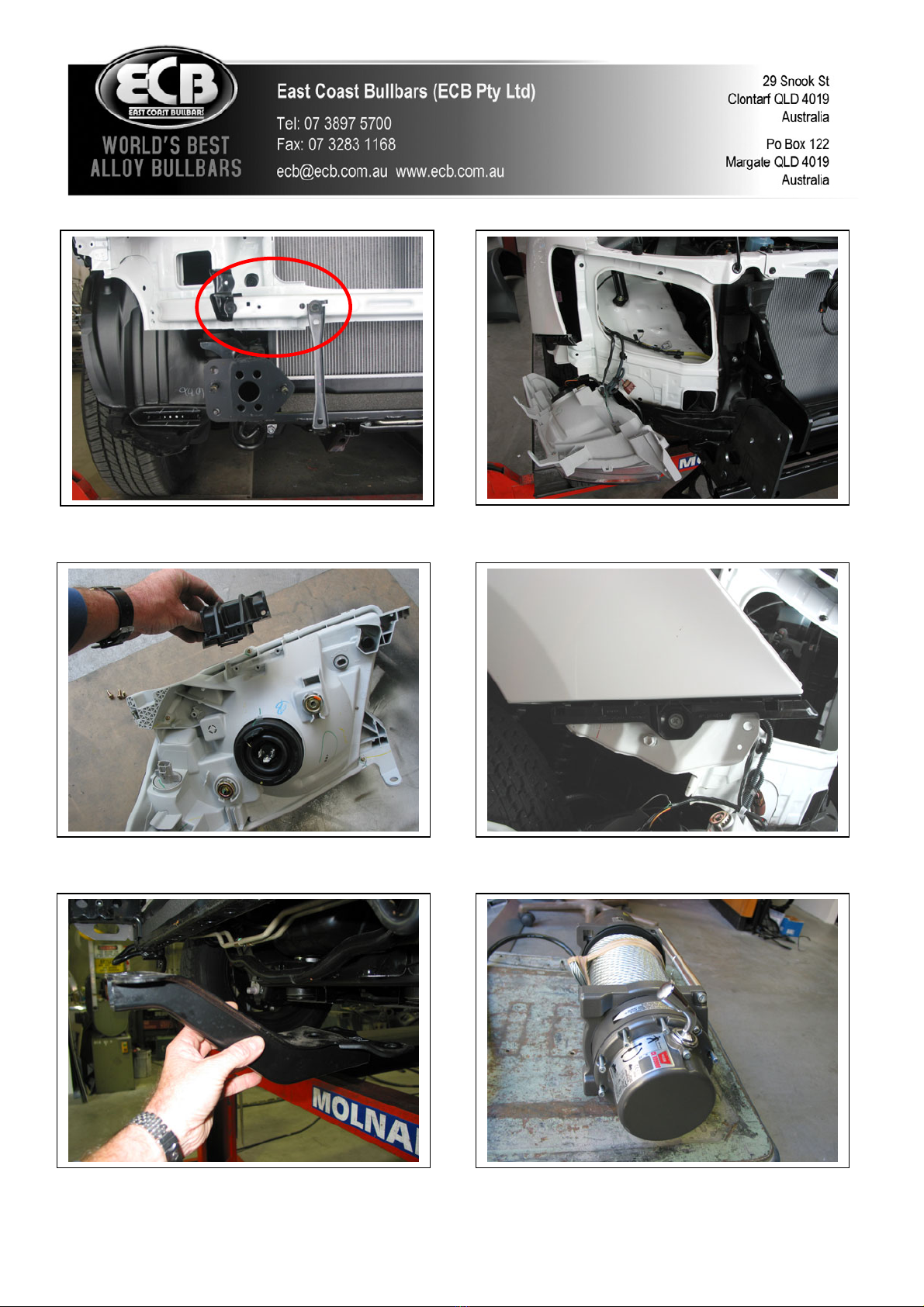
28. Fit ECB LED indicator / park lights (supplied) into protection bar as per instructions supplied with the LED
indicator kit. NOTE: Ensure park light is to outside. See figure 20.
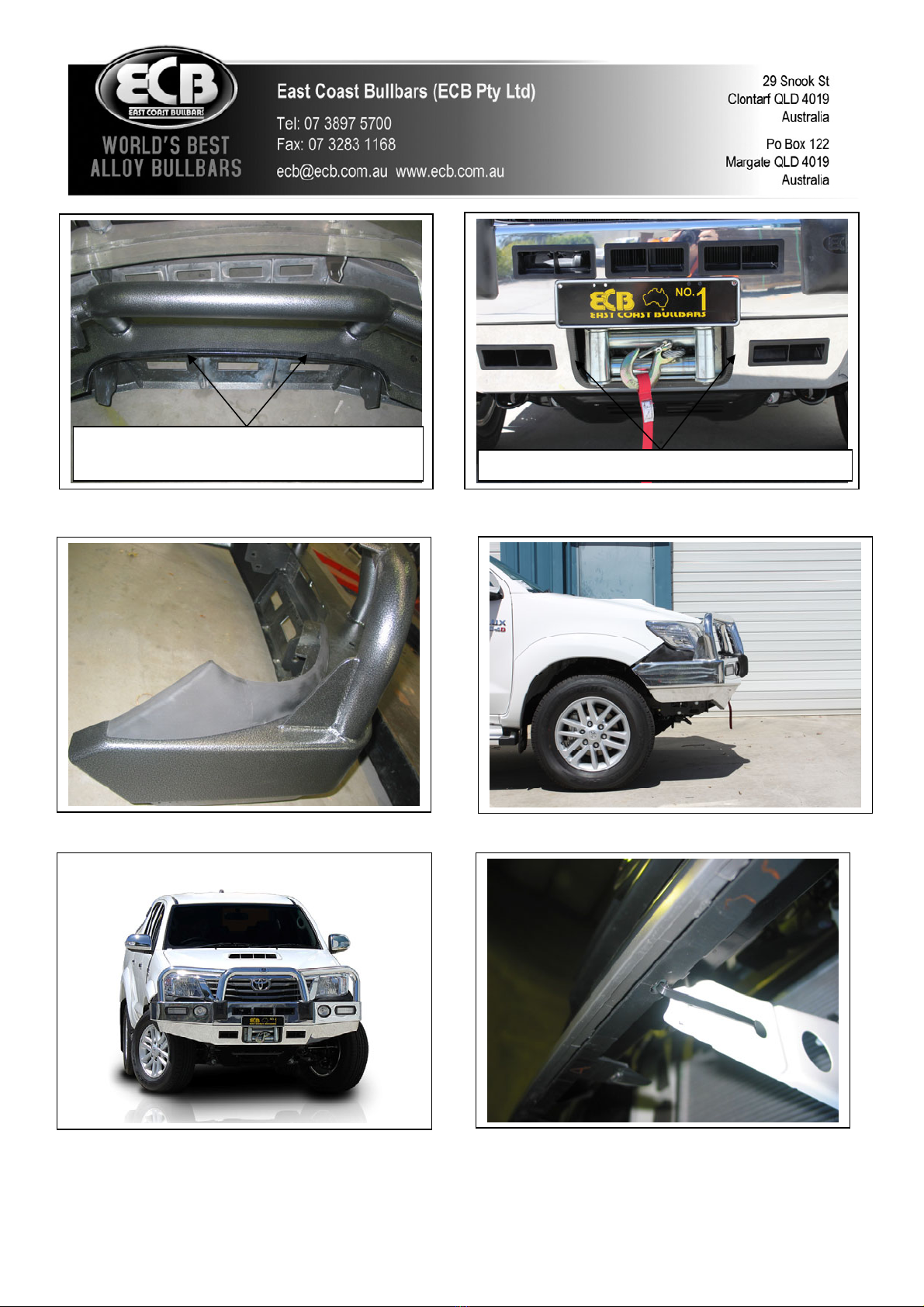
29. Attach ECB 6mm clip lock trim to centre section of protection bar and centre cut out of skirt. See figures 21 and
22.
30. Attach ECB infill trims (supplied) to protector bar. Use M6 nyloc nuts and flat washers (supplied) FINGER
TIGHTEN ONLY. See figure 23.
31. Fit ECB protection bar to outside of steel mounting brackets. Use ½ x 1 ¾ bolts, nuts, flat and spring washers
(supplied). FINGER TIGHTEN ONLY.
32. Align ECB protection bar with vehicle ensuring a gap of 10 to 12mm between protection bar and guard / flare at
sides. See figure 24 for side view and figure 25 for front view TIGHTEN ALL BOLTS. Impact wrench access
is from grille area. NOTE: A 10mm to 12mm gap each side is critical to allow for body/chassis twist in rough
terrain.
33. Connect indicator / park light wiring and CHECK OPERATION.
34. Carefully drill three 3/16 holes in lower lip on grille, one in centre and one each side, refit grille to vehicle. Zip
tie bottom of grille to head light / indicator assemblies and to steel bracket in centre. See figures 26 and 27.
35. Align ECB infill trims with vehicle and protection bar. TIGHTEN NUTS FIRM ONLY – DO NOT
OVERTIGHTEN.
36. Fit ECB inner guard bracket (supplied) to lower radiator support using one 10mm head bolt from lower bumper
mounts to radiator support and one M6x20 bolt, washer and nyloc nut (supplied)per side. See figure 28. Secure
outer hole in liner to inner guard bracket with bolt supplied M6 x 20 bolt, washers and nyloc nuts (supplied).
Then secure second hole in inner guard bracket to liner with M6 x 20 bolt , washer and nyloc nut (supplied),
ensure this is not pulled to tight as it may cause liner to tear. TIGHTEN bolts and trim any excess liner off. On
passenger side ensure washer bottle stays covered after trim. See figure 29.
ENSURE NUMBER PLATE IS CLEARLY VISABLE
Note: When fitting/refitting the licence plate to the vehicle, ensure there is no obstruction to licence plate vision in
accordance with local authorities. If required relocate licence plate to an alternate location.
Further VFPS Notes:
a) Do not attach VFPS to the vehicle using anchorages not intended for this purpose (e.g. engine mounting bolts).
b) Do not use this product for any vehicle make or model, other than those specified by the VFPS manufacturer.
c) Do not remove the plaque or label from the VFPS.
d) Do not modify the structure of the VFPS in any way.
e) No accessory or fitment should project forward of the VFPS forward profile.
f) ENSURE THESE INSTRUCTIONS ARE LEFT WITH VEHICLE OWNER AND/OR OPERATOR.
IMPORTANT INFORMATION
Periodically check bolts and nuts for correct tightness, especially if travelling on rough roads

FITTING KIT
1 – Pair steel mounting brackets 10 – 3/8 nuts
1 – steel winch mounting bracket 6 – ½ x 1 ¾ bolts
1 – Steel control box mount 14 – ½ flat washers
2 – Steel inner guard brackets 8 – ½ spring washers
1 – 95 x 50 x 6 steel spacer plate (two 10mm holes) 6 – ½ nuts
2 – 10nb tube spacer, 52mm long 4 – ¼ flat washers
2 – M12 x 35 x 1.25 bolts 6 – M6 x 20 bolts
4 – M10 x 35 x 1.25 bolts 18 – M6 flat washers
4 – M8 x 30 x 1.25 bolts 12 – M6 nyloc nuts
6 – M8 flat washers 1 – Pair ECB Hilux infills (IC11LUXINFL)
4 – M8 spring washers 1 – ECB indicator park light kit
2 – M8 nuts 1 – Quick Click Indi / Park kit (IC11HILLED100H)
2 – 3/8 x 4 bolts 1 – 1100mm length, 6mm clip lock trim
4 – 3/8 x 1 ½ bolts 1 – 700mm length , 6mm clip lock trim
6 – 3/8 x 1 ¼ bolts 6 – 300mm zip ties
24 – 3/8 flat washers 6 – 150mm zip ties
18 – 3/8 spring washers
Remove cross member
.© Copyright – ECB Pty Ltd – 2012 4
Figure 1 Figure 2: Trim lower section from air dam.
Passengers side shown.
.© Copyright – ECB Pty Ltd – 2012 5
Figure 4 – Remove headlight
Figure 3 – Drivers side shown
Figure 6 - Remove plastic bumper support from
under guard.
Figure 5 – Removing trim from lower headlights
Figure 7 Figure 8
.© Copyright – ECB Pty Ltd – 2012 6
Figure 13
Figure 11
Figure 9 Figure 10
Figure 12
Figure 14 - Finger tighten only at this time
.© Copyright – ECB Pty Ltd – 2012 7
Figure 15 Figure 16
Stainless steel self-tappers
Figure 18
Figure 17
Figure 20
Figure 19
Attach 6mm cli
p
lock trim
Attach 6mm clip lock trim
Note: Non winch bar shown
Figure 22
Figure 21
.
Figure 23 Figure 24
.© Copyright – ECB Pty Ltd – 2012 8
Figure 25 Figure 26 – Centre grille attach point
.© Copyright – ECB Pty Ltd – 2012 9
Figure 27 – Side grille attachment point. Drivers
side shown.
Figure 28 –Drivers side shown
Figure 29 –Passengers side shown

We value your comments
Dear Fitter,
ECB would like to know how you went with the installation of this product. We value your comment and may need to
contact you to clarify some details so please complete your contact details clearly.
We would appreciate if you could complete as many of the following details as possible.
Your Name:
Your contact No.
Product Part No.
Product Invoice No.
Product Description:
Make, model, and year of vehicle:
Product Work Order No.
Company your from/Company product purchased from:
Date of Fitment: ____/____/____
Yes No
Was the fitting hardware supplied complete?
If no what was not supplied
______________________________________________________________________________________
______________________________________________________________________________________
______________________________________________________________________________________
Yes No
Did the installation go well?
Please provide comments
______________________________________________________________________________________
______________________________________________________________________________________
______________________________________________________________________________________
______________________________________________________________________________________
Please draw diagrams if you need to.
Post to Fax to
Reply Paid 122 (07) 3283 1168
PO Box 122
Margate QLD 4019
.© Copyright – ECB Pty Ltd – 2012 10
DESPATCH CHECKLIST
BT128SY
Work Order #
Finish:
Transport:
Due Date:
See other side of
this page for
photos of all
mounts
O1 – Pair steel mounting brackets (pair)
O1 – Winch mounting bracket
O1 – Control box bracket
O2 – Steel inner guard brackets
O2 – 90 x 50 x 6 steel spacer plate
O1 – Bolt kit
O1 – 1100mm length, 6mm clip lock trim
O1 – 700mm length, 6mm clip lock trim
O1 – ECB LED Indicator / Park light kit.
O1 – Pair Hilux infill trims. (IC11LUXINFL)
O1 – Quick Click Indi / Park kit (IC11HILLED100H)
O2 – ECB overriders – Fitted to bar.
O5 – 6mm air scoops – Fitted to bar.
All parts checked and completed by:
Is this product “the best it can be” Yes ______/______
Wrapper’s initials / Checker initials
If NO fix before continuing
Nut and bolts: __________________________Date__/__/__
Order control: __________________________Date__/__/__
Final wrap check: __________________________Date__/__/__
.© Copyright – ECB Pty Ltd – 2012 11

.© Copyright – ECB Pty Ltd – 2012 12
3 BOLTS
Infill Trims - ICHILINFIL
Table of contents
Other ECB Automobile Accessories manuals


Popular Automobile Accessories manuals by other brands


ULTIMATE SPEED
ULTIMATE SPEED 279746 Assembly and Safety Advice

SSV Works
SSV Works DF-F65 manual

ULTIMATE SPEED
ULTIMATE SPEED CARBON Assembly and Safety Advice

Witter
Witter F174 Fitting instructions

WeatherTech
WeatherTech No-Drill installation instructions

TAUBENREUTHER
TAUBENREUTHER 1-336050 Installation instruction