ECHO MARINE ECHO Tec Watermakers Modular DC Series User manual

MODULAR DC SERIES
200-DML-1 / 240-DML-1 / 260-DML-1
OWNERS MANUAL
PAGES
2
Introduction
3
Specifications
4-5
Standard System Features, Options and Accessories
6
Flow Diagram
7-10
Installation Instructions
11
Installation Instructions Options
12-13
System Operation, Shut Down and Flush Procedure
14
Membrane Storage and Cleaning Procedure
15
Maintenance Timetable
16
Troubleshooting Guide
17
Membrane Element and End Plug Service Instructions
18-19
High Pressure Pump Service Instructions
20-21
Warranty

2
INTRODUCTION
ECHO MARINE LTD.
1st Avenue South, Chaguaramas, Trinidad W.I.
Telephone: 1-868-634-2027 Fax: 1-868-634-2026
E-mail: echotec@echo-marine.com
www.echotecwatermakers.com
Rev.2014.8
Congratulations on the purchase of your ECHOTec Watermaker. We trust that you will be
completely satisfied with our product. We thoroughly bench test every desalination
system before shipping and are confident that we have manufactured the finest
watermaker on the market.
Your watermaker will provide you with clean and safe drinking water for many years to
come if you follow the simple instructions in this owners’ guide. The purpose of this
manual is to allow you to become familiar with each component of your new ECHOTec
Watermaker.
By understanding the function, importance and normal operation of each part in the
system, the operator can readily diagnose problems when they first develop. Such
problems are easily corrected and require minor adjustments. If left unattended, a small
problem in one component may affect the rest of the system and can lead to an
expensive repair.
If you have any questions regarding the installation, operation or maintenance of your
watermaker please contact us. We are always happy to assist!

3
SPECIFICATIONS
RATED PERFORMANCE:
ECHOTec Model
Gallons per hour
Liters per hour
200 - DML - 1
8.5
32
240 - DML - 1
11
42
260 - DML - 1
13
50
Reverse Osmosis performance varies with the feed water temperature and salinity.
The rated performance is tested at 26C / 80F water temperature and 33g NaCl/ltr.
RO MEMBRANE TYPE:
Standard size high rejection TFC Polyamide, thin film composite, spiral wound, single pass reverse
osmosis element.
PRODUCT WATER QUALITY: minimum 500 ppm TDS
FEED WATER SALINITY RANGE: up to 50,000 ppm TDS ( NaCl )
PH RANGE: 4 –11
CHLORINE TOLERANCE: 1000 ppm hours
FEED WATER PRESSURE: 5”Hg to 60 psi
OPERATING PRESSURE: 900 psi
FEED WATER TEMPERATURE RANGE: min. 33F / 0.5C, max 113F / 45C
ELECTRICAL POWER REQUIREMENTS:
ECHOTec Model
amps @ 12.5 V DC
amps @ 25 V DC
amps @ 48 V DC
200 - DML - 1
19.8
9.5
n/a
240 - DML - 1
27
13.5
n/a
260 - DML - 1
38
18
9

4
STANDARD SYSTEM FEATURES
1) 1 PVC sea strainer
2 3/4” NPT x 5/8” barbed hose connection
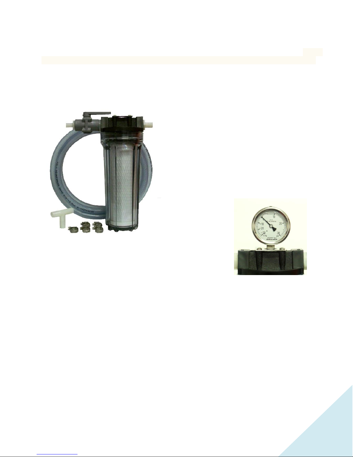
2) Pre-Filter complete with 20 micron cartridge (5 and 20 micron with optional boost pump)
1 Stainless steel bracket with 8 screws
1 Service valve with 1 Nylon nipple and 3 barbed hose connectors (with boost pump) or
1 flush/storage valve with 1 Nylon nipple and 1 NPT female tee (without boost pump)
1 Filter wrench
3) 1 High-pressure pump unit with vibration dampers
4) 1 Pressure vessel with reverse osmosis membrane
5) 1 Stainless steel control panel completely assembled with
1 Pressure control valve
1 High pressure gauge
1 Product flow meter
1 Diverter (3-way) valve
1 Breaker (without boost pump) or
2 Breakers (with boost pump)
6) 1 Hardener / pH neutralizer kit with mineral element and 2pcs 3/8” compression fittings
1 Stainless steel bracket with 8 screws
7) 15 feet / 4.5 meter high pressure hose with 2 x stainless steel high pressure fittings attached
2 x stainless steel field attachable high pressure fittings
8) 20 feet / 6 meter 3/8” blue product water tubing
10 feet / 3 meter 5/8” braided intake hose
10 feet / 3 meter 1/2” braided reject hose or 10 mm tubing
9) 17 Stainless steel hose clamps (with boost pump) or
12 Stainless steel hose clamps (without boost pump)
5
OPTIONS AND ACCESSORIES
If the high-pressure pump is installed less than 1 foot below the waterline or an additional 5micron pre-
filter is added, the installation of an optional boost pump is recommended. The boost pump also extents
pre-filter element life, reduces maintenance and assists in priming the system after pre-filter changes.
Boost pump with intake hose barb, outlet hose barb, 4 feet / 1.2 meter wire reinforced intake hose,
10 feet / 3 meter braided feed hose, 5 micron pre-filter housing, bracket, fittings and cartridge (all
assembled).
5 Micron Pre-filter Housing (1 filter housing, 1 pre-filter cartridge, 1 bracket, 1 3/4” NPT nipple)
An additional 5 micron pre-filter is only recommended in connection with the optional boost pump.
Note: The 5micron filter must be installed as a second filter in flow direction
Maintenance Kit
10 Pre-filters, 5 and/or 20 microns
1 Spare sea strainer screen
2 Active carbon filters (fresh water flush)
1ltr. High pressure pump oil
Extended Maintenance Kit
2 Motor brushes
1 Acid cleaning compound
1 Alkaline cleaning compound
2 Storage compounds (Biocide)
1 Complete spare seal and O ring kit (except high pressure pump)
Fresh water flush kit for installation with boost
pump (filter housing, charcoal cartridge,
stainless steel bracket, 8 screws, shut off valve,
2 x 1/2” hose barb connectors, 1/2” tee, 10ft
1/2” braided hose, 5 x 1/2” hose clamps)
Fresh water flush kit for installation without
boost pump (filter housing, charcoal cartridge,
stainless steel bracket, 8 screws, shut off valve,
2 x 5/8” hose barb connectors, 5/8” tee, 10ft
5/8” braided hose, 5 x 5/8” hose clamps)
Low pressure gauge
The low pressure gauge indicates when the pre-filters have to be
changed. Select pressure range according to freshwater pressure.

6
FLOW DIAGRAM
Shown with Optional Equipment

7
INSTALLATION INSTRUCTIONS
HIGH PRESSURE PUMP UNIT
Mount the high pressure pump/motor unit horizontally in a dry and ventilated location. Maximum ambient
temperature for continuous duty is 40˚C / 104˚F.
CAUTION: Motor gets hot during prolonged operation.
PRESSURE VESSEL (MEMBRANE HOUSING)
Mount the pressure vessel(s) with the provided brackets vertical (with the flow upwards) or horizontal
in a convenient location away from the heat of the engine as close as possible to the high pressure
pump.
The membrane is sealed within its housing by plugs at both ends. Inside the housing is a small amount
of preservative to keep the membrane moist and prevent bacterial growth. The shelf life of the
preservative, under best conditions, is one year.
When all other components and hoses/tubes are completely assembled, remove the caps on the high
pressure fittings and the sealed tube from the product water outlet on the membrane housing/s and
then finish making all final hose/tube connections. This will insure that the membrane is kept moist.
CONTROL PANEL
Mount the control panel preferable trough a bulkhead or on any panel in an easily accessible
location as close as practical to the membrane housing(s).

8
SEA STRAINER
Mount the sea strainer with the provided 3/4" NPT nylon nipple directly to
the intake of the 20 micron pre-filter housing. If an optional boost pump is
required (refer to “Available Options and Accessories”), mount the sea
strainer in a serviceable location in between the sea-cock of your choice
and the boost pump.
CAUTION: To avoid excessive mechanical stress, do not mount the sea
strainer directly to the sea-cock.
Connect the barbed fittings with the supplied coil reinforced intake hose and secure all hoses below water
level with two hose clamps. For boost pump installation refer to the installation instructions for optional
equipment (page 11).
FILTER HOUSINGS
Mount the pre-filter in a serviceable location and connect the bottom port of the cleaning / storage valve
with the 5/8” reinforced vinyl hose to the intake hose barb fitting of the high-pressure pump (lower fitting).
Secure the hose with hose supplied clamps.
CAUTION: Install all plumbing to eliminate any air pockets in the system.
CAUTION: If you have to re-seal NPT fittings, use a maximum of three wraps of Teflon tape on the
threads. Always keep the tape back from the end of the fittings (at least two threads). Do not allow any
tape to enter the system.
HIGH PRESSURE HOSE
The high pressure hose has factory mounted high pressure couplings on each end (also included are two
field attachable fittings). This hose comes in a 15 feet / 4.5 m length, so it may be cut to suit your needs.
Leave a little extra length of hose to avoid stress on the system components.
CAUTION: Never bend the high pressure hose tighter than a 6”/15 cm radius.
Assembly instructions for the stainless steel field attachable high-pressure couplings
1) Cut the hose in a clean 90angle preferably with a cutting disc or fine tooth hacksaw.
2) Un-assemble the coupling (remove threaded inner part from outer part).

9
3) Rotate the socket (outer part) anti clock wise on to the hose until hose bottoms. Back the hose out
½ turn to allow for expansion of the hose during assembly.
4) Apply dishwashing liquid mixed 1:1 with water on to the nipple (inner part) of the high-pressure
fitting and the inside of the hose.
5) Hold the socket preferably in a vice and screw the nipple all the way into the hose. The straight
fitting is supplied with a hexagonal plug as an assembly tool.
Run one of the high-pressure hoses from the output of the HP pump (O ring sealed fitting) to the O ring
sealed fitting at the end of the membrane that is marked IN.
CAUTION: A minimum hose length of 3 feet / 1m is required for pulsation dampening. The hose can be
coiled where needed.
Run the second high-pressure hose from the outlet of the RO membrane housing to the pressure control
valve in the control panel. Do not over tighten the high pressure fittings. They are O-ring sealed and need
little torque to lock only.
CAUTION: When connecting the high pressure hose to the membrane housing (s), avoid over tightening.
The fitting is o-ring sealed and does not require much torque.
PRODUCT WATER TUBING
Using the blue product water tubing, connect the center fitting of the membrane housing with the bottom
fitting (inlet) of the flow meter in the control panel. Connect the tubing or hose from each output port of
the 3-way valve to your water tank and to the taste/test station of your choice.
CAUTION: Under no circumstances should the product water line be allowed to become blocked while
the system is running. Do not install shut-off valves anywhere in this line.
CAUTION: Do not allow chlorinated water from your storage tank to flow back into the R.O. membrane.
You may directly “T” your product water line into the tank vent (Refer to the Flow Diagram). This avoids
chlorinated water to back flow from your water tanks into the R.O. membrane and does not require a new
fitting in your tank. This solution requires a vent of sufficient diameter as the product water will have to
flow against the escaping air. If the product line must be installed below tank water line, an optional non-
return valve should be installed.
An existing hand pump style spigot, with a check valve only can be used as test station. If using this type of
spigot for two sources (tank and test), install low-pressure non-return valves in the tank- and product line
and “T” both into the existing hand pump spigot.

10
HARDENER / PH NEUTRALIZER KIT
THOUGH-HULL FITTING (not supplied)
ELECTRICAL INSTALLATION
The electrical installation should only be done by a professional electrician according to the local
regulations with regards to safety. Electrical installation materials are not supplied.
The ECHOTec post treatment element contains a mixture
of minerals that returns bicarbonate alkalinity, correcting
pH only enough to reach a neutral equilibrium. This
dramatically reduces corrosion on metal tanks, boilers,
washing machines and plumbing due to acidic product
water.
Install the hardener / pH neutralizer housing at a
serviceable location in line with the product water tubing
from the diverter valve on the control panel to the
freshwater storage tank. (Refer to flow diagram on page 6)
Note: Observe the flow direction indicated on the housing.
REJECT WATER TUBING / HOSE (BRINE)
Connect the outlet of the pressure control valve on the
control panel with a reject thru-hull of your choice
(preferably above the water line as an indication for proper
operation of the system).
The boat’s designated intake thru-hull should be located in
an area that will always be in the water when the boat is
used under normal running conditions,
A trough hull fitting with strainer scoop could be helpful.
Installed with the opening facing the bow, it typically
generates a small amount of pressure while moving
through the water. It is important not to place the thru-
hull fitting directly forward of a speedometer pickup. It is
also wise not to place the intake thru-hull slightly aft or
outboard of a holding tank, head or galley sink overboard
discharge.

11
INSTALLATION INSTRUCTION –OPTIONAL EQUIPMENT
BOOST PUMP
Install the submersible boost pump with the electric motor sideways (horizontal) below the water line, in
between the sea strainer and the pre-filter(s). The intake is at the center of the pump. The outlet should
ideally point upwards or sideways with the fitting to the top to prevent air pockets.
Avoid elbows/90˚fittings in your plumbing if possible. The complete pump head can be turned in case the
outlet direction is not suitable for your installation.
The ECHOTec “Orbital” Magnetic Drive Pumps eliminate the conventional shaft seals found in most pumps.
This means that there is no rotating seal to wear and allow the liquid being pumped to leak out.
We rely on the liquid being pumped to lubricate the impeller-magnet assembly spinning on the stationary
spindle. If the pump is run dry for longer than 10 minutes, the assembly may “freeze” onto the spindle.
All pumps can be serviced with the use of a screwdriver. The only moving part in the pump other than the
motor is the impeller-magnet assembly. This assembly rotates on a stationary spindle and up against a
thrust washer.
Note: The boost pump includes the 5 micron pre-filter option.
5 MICRON PRE-FILTER
Connect the filter housing with the supplied ¾” nylon nipple to the standard filter housing and
reconnect the reinforced vinyl hose. The 5micron cartridge has to be installed as the second filter in
flow direction.
5 MICRON PRE FILTER WITH LOW PRESSURE GAUGE
The optional 5micron pre filter housing with low pressure gauge has to be installed as a second filter in
flow direction.
FRESHWATER FLUSH SYSTEM
Install the active carbon filter housing at an easily accessible location close to your seawater intake line
and any pressurized water line. Connect the fitting on the shut off valve of the carbon filter housing to
your boats’ pressurized water line.
Connect the filter outlet to the supplied T-connector. Connect the two remaining ports of the T-
connector to the outlet of the storage/cleaning valve on the pre-filter housing and to the intake of the
high pressure pump (refer to the flow diagram).

12
SYSTEM OPERATION INSTRUCTIONS
CAUTION: The reverse osmosis membrane contains a preservative solution to prevent microbiological
growth. If ingested, it may cause irritation of the gastro-intestinal tract. Therefore, discard all the product
water for at least thirty minutes of initial operation or after system storage before drinking or before use in
food preparations!
CAUTION: Do not operate the system using contaminated feed water sources (oil, chlorine or other
chemicals).
CAUTION: Check proper oil level with dipstick or show glass (center of show glass).
CAUTION: Have you removed the shipping plug from the high pressure pump and replaced with the
enclosed breather oil cap? Failure to do so may damage the crankshaft oil seals of the pump.
1) Open the seawater intake valve (sea cock).
2) Open the pressure control valve, on the control panel, all the way counter-clockwise.
CAUTION: Never start the system with the high-pressure control valve closed.
3) Set the cleaning/storage valve to the pre-filter position (towards the filter).
4) Set the diverter valve to sample position (left).
5) Switch on the boost pump (optional).
6) Switch on the high pressure pump.
7) Flush the air out of the system. Crack open pre- filter housings if needed.
Check for brine discharge at the output location.
CAUTION: Never allow any leaks in your hose or tube connections.
CAUTION: Do not attempt to re-seal the stainless steel product water outlet fitting on the membrane
vessel end cap by further tightening as this could damage the thread of the plug. Remove the fitting, apply
new Teflon tape, insert the fitting and hand tighten plus ¼ turn.
8) Close the pressure control valve slowly clockwise to allow air bubbles to work themselves
out of the system.
9) Adjust the water pressure to achieve the specified product output with a maximum reading of
900 PSI on the pressure gauge in the control panel. If you operate the watermaker in brackish
or lake water, adjust the working pressure not to exceed the specified product water rate.
10) Taste the product water at your sample station. If the water is pure, switch the
diverter valve to fill your storage tank.

13
SYSTEM SHUT DOWN PROCEDURE
1) Switch the diverter valve to sample station.
2) Open the pressure control valve all the way counter-clockwise.
3) Switch off the electric motor and the boost pump (if installed).
4) Close the seawater intake valve.
FRESH WATER FLUSH PROCEDURE
The fresh water flush exchanges the seawater in the membrane element/s with fresh water und should be
performed after each use of the watermaker. Skipping the flush does not save water as the product on next
operation must be dumped longer to clear the membrane element. The simple flushing procedure avoids
biological growth due to the dying microorganisms contained in seawater and dissolves mineral build up
that may clog the membrane element/s. Repeated every 14 days, the fresh water flush also avoids the need
for chemical preservation, otherwise to be performed for long-term storage.
CAUTION: The boats fresh water pressure should not exceed the range of the low pressure gauge.
1) Open the pressure control valve all the way (two full rounds after the spring releases) counter
clockwise.
2) Close the sea water intake valve or switch the cleaning/storage valve to the closed position.
3) Open the fresh water flush valve.
Your boats’ fresh water supply pump should now turn on (larger fresh water pumps will cycle on and off).
Allow fresh water to flow until all salt water is flushed out of the RO System. For the next flush procedure,
test how long it takes until the brine at the outlet becomes fresh.
PRE-FILTER BACKWASH PROCEDURE
As part of a long term storage, you may remove the pre-filter cartridges from the housings or perform a
pre-filter backwash procedure. If there is no momentary shortage of fresh water, the back wash may also
be useful to reduce product water discharge time until the product is free of odor after each start up.
1) Open the seacock and switch the cleaning/storage valve to the sea water position.
2) Allow fresh water to flow until all salt water is flushed out of the pre-filter(s), boost pump and the
sea strainer (approximately 30 seconds, depending on the flow rate of your vessel’s fresh water
pump).
3) Close the seacock.
MEMBRANE STORAGE PROCEDURE
If you intend to store your watermaker for more than ten days, growth of micro-organism may degrade the
RO membrane(s) performance and the RO membrane(s) should be flushed with a biocide solution. This will
preserve the membrane for long-term storage of up to ten months.
If you have installed the optional fresh water flush system, it is recommended to back flush the pre-filter(s),
the boost pump and the sea strainer with fresh water (see above). Close the seawater intake valve (sea
cock) and remove the pre-filter cartridge(s).

14
1) In a clean plastic container, mix 2.5 gallons / 10 liters of un-chlorinated fresh water with 100 grams
(1/3 container) of ECHOTec membrane preservative # 3 (Metabisulfite)
2) Switch the three-way valve to the cleaning/storage position.
3) Switch the diverter valve to the sample position.
4) Open the pressure control valve all the way counter clockwise (two full rounds after the spring
releases).
5) Use a large funnel or open container with barbed fitting to pour the solution into the
cleaning/storage hose or lead the hose into an elevated plastic container while running the high-
pressure pump. When the solution has been infused, switch off the watermaker.
Your watermaker is now prepared for a shutdown period of ten months.
CAUTION: After storage, discard the product water for at least thirty minutes of initial operation before
drinking or before use in food preparations.
MEMBRANE CLEANING PROCEDURE
ECHO Tec membrane element may be chemically cleaned when the product water output drops by 15% of
the specified amount. The frequency of this occurring will vary greatly depending upon feed water quality.
Fouling of the membrane will naturally occur during normal usage. Increased amounts of fouling without
proper cleaning of the membrane will reduce the performance of your water maker. A drop in production
of approximately 10% is normal and expected during the first year of operation.
Note: Do not clean when product salinity high. Clean only to restore output!
CAUTION: The use of chemicals or cleaning methods other than those outlined in the cleaning instructions
will void the ECHO Tec Warranty.
CAUTION: Cleaning chemical #1 is an alkaline detergent. See warning label on side of the container and
observe all safety precautions on label.
CAUTION: Cleaning chemical #2 is an acid, a mineral scale remover. See warning label onside of container
and observe all safety precautions on label.
CAUTION: Do not mix different cleaning chemicals together. Do not use different cleaning chemicals
together at the same time.
To clean the ECHO Tec. reverse osmosis membrane mix a solution of 1.5 to 2 % by weight with warm non-
chlorinated water (113° F / 45° C) in a clean plastic container. Use 10 ltr / 2.5 gal with 200 g or 2/3
container cleaning agent.
For safety reasons, we do not recommend you to install a 3 way re-circulating valve to facilitate the service
procedure. Disconnect the intake and reject water hose and lead them in the plastic container. Re-
circulate the solution intermittent without pressure for up to 60 min. There will be no flow at the fresh
water outlet.
CAUTION: Observe the maximum operating temperature of 113° F / 45° C. The high pressure pump might
over heat the solution on re-circulating.
It is important that most of the fresh water remaining from the last flush is dumped before the
reject hose is led in the cleaning bucket for re-circulation in order to avoid diluting the solution.
Use cleaning chemical #1 first. Only if the performance does not improve, use the
acid cleaner #2 at the same ratio and instruction

15
MAINTENANCE TIMETABLE
The following maintenance timetable is an estimate of the time intervals at which maintenance may be
required only. This schedule must be adjusted to the regularity of usage, the condition of the intake water,
the length of time the system is exposed to seawater and the total running time following each system
cleaning.
COMPONENT
MAINTENANCE REQUIRED
TIME INTERVAL (INTERMITTENT DUTY)
Sea Strainer
Inspect and clean
screen and housing…
every 200 hrs or when clogged. Observe low
pressure gauge if installed.
Pre filters(s)
Replace or clean element(s) and
clean housing(s)…
Boost pump: when pressure is lower than 0
PSI. No Boost pump: pressure lower than 5”Hg
Hardener / pH
neutralizer
Replace or refilled with the mineral
mix of another cartridge…
when 25% of the content has been dissolved to
guaranty sufficient contact surface
Carbon flush
filter
Replace element…
every 6 months
High pressure
pump
Change
crankcase oil…
7.5 oz./0.2 L SAE 90 Wt, non-detergent
Initial change after 50 hrs.
every 300 operating hours or 12 months
High pressure
pump
Change seals and O-rings…
every 5000 hrs or 3 years.
R.O. Membrane
Clean with acid and/or alkaline
cleaning compound…
Replace…
Note: Do not clean when TDS reads
high. Clean only to restore output!
when production decreases by 15%.
when cleaning does not
increase production.
Flow meter
*Infuse muriatic acid and rinse well…
when discolored/dirty
* Set the diverter valve to the sample position. Disconnect the product water tubing from the product port
at the membrane vessel and carefully infuse Muriatic acid, KR1 or Ospho with a syringe into the product
water tubing. Once the discoloring has cleared, re-connect the tubing, run the system and rinse the flow
meter with the product water. CAUTION: Adhere to the safety advises of the cleaning agents.

16
TROUBLESHOOTING GUIDE
MALFUNCTION
CAUSE
REMEDY
Inability to build up
pressure…
...with high pressure
gauge fluttering.
…with loud noise from
HP-pump.
(Low pressure gauge
reads below 10”Hg)
…during navigation
…with drop in RPM
Air enters intake plumbing.
Air in intake system
High pressure pump valve
stuck after long storage time.
Seacock closed
Seacock clogged (Barnacles?)
Strainer, filter/s fouled
Through hull fitting in wrong
location (suction trough
movement).
Motor brushes worn
Tighten all hose clamps.
Allow more time to prime. If no boost pump is
installed, perform freshwater flush to assist
priming.
Open one by one all six hexagonal valve covers.
Inspect valves for movement.
Open seacock
Clean seacock
Clean strainer, change/clean filter/s.
Use strainer scoop (page 11).
Replace brushes
Pressure drops
frequently with change
of noise…
…during navigation
Air enters intake plumbing.
Air enters sea water intake
during navigation.
Tighten all hose clamps. Reseal NPT fittings.
Move through hull fitting to lower location.
Excessive leakage
between the high
pressure pump head
and crankcase…
…with water in crankcase
Worn high pressure seals
Cracked ceramic plunger
Cracked ceramic plunger
and/or worn HP/oil seals
Replace high pressure seals
Inspect for hairline crack. Replace plunger
and HP seals (page 18 / 3).
Inspect for hairline crack. Replace plunger (if
needed), high pressure seals and oil seals.
Product salinity reads
above 500ppmTDS.
Membrane element has
reached its service life time.
Replace membrane element. See instructions
on page 17.
Product output below
specification.
Low voltage or bad electrical
contact
Membrane element clogged
or reached its service life
time.
Check voltage directly at motor cables.
Clean membrane element (page 14).
Replace membrane element (page 17).
Leak on pressure vessel
end cap from salt water
…from fresh water
O-ring worn
Product port Teflon seal worn
Remove and inspect plug (page 17). Change O-
ring/s as needed.
Remove port, re-seal, install hand tight + ¼ turn

17
MEMBRANE ELEMENT AND END PLUG SERVICE INSTRUCTIONS
1) Remove the high pressure hoses and product tubing from the pressure vessel
2) If needed remove the complete vessel
3) Remove the three M6 bolts with a 5mm allen key on both sides of the vessel.
4) Remove the three locking plates (locks) on both sides.
5) Holding the product port, pull the product port end plug in one fast pull out of the vessel.
Note: Should the plugs O-ring (PL01) get stuck in the locks groove of the pressure vessel, it will be more
difficult to pull the plug. Tap the plug in and pull more vigorously.
If the product port is mounted on the high pressure OUT side:
6) Using a needle nose pliers, pull the membrane element on the product tube in flow direction.
6b) Push out the remaining end plug from the opposite side with a pipe, boat hook, etc.
If the product port is mounted on the high pressure IN side:
6) Using a short pipe or wooden support, push out the membrane element together with the
remaining end plug.
Inspect the end plugs for hairline cracks or damages on the O-rings and O-ring grooves.
7) Insert the new membrane element, observing the correct position and direction of the lipped
seal ring: High pressure entry side of the membrane, lip against flow direction.
8) If needed, clean the product port and end plug threads from remaining Teflon sealant and
re-apply 3 wraps only.
11) Insert the end plugs and reassemble all components visa versa.
CAUTION: Do not over tightening the product port/s. Hand tide plus ¼ turn. Thread may damage!
18
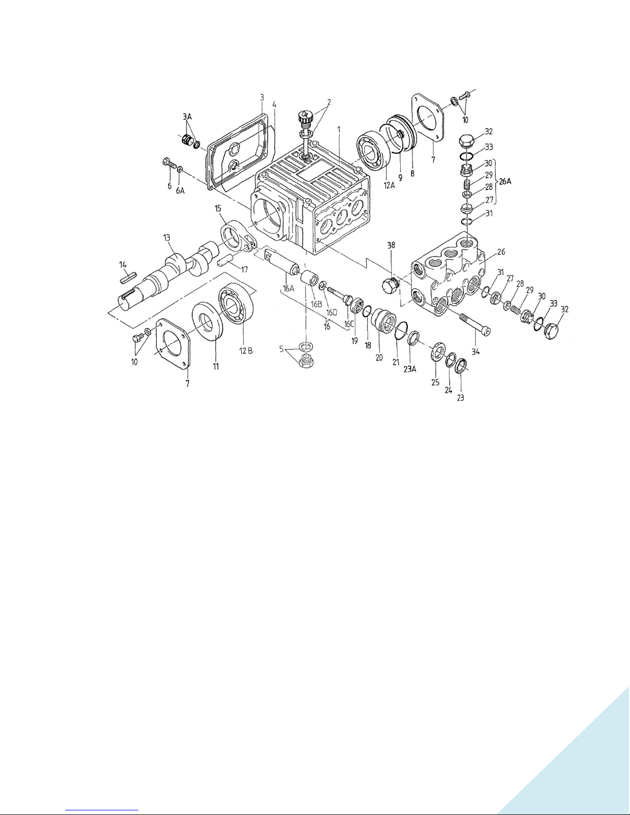
HIGH PRESSURE PUMP PARTS AND SERVICE INSTRUCTIONS
DISASSEMBLY SEQUENCE OF THE PUMP HEAD
Refer to the pump diagram.
1) Remove the three discharge valve plugs and the three inlet valve plugs (32), with a 22 mm socket
wrench. Inspect the O-ring (33) for wear and replace if damaged.
2) With needle nose pliers, remove the inlet and discharge valve assemblies (32X). Insert a small
screwdriver between the valve seat (27) and the valve spring retainer (30) to separate the valve
assembly. Remove the O-ring (31). Inspect all parts for wear and replace if necessary.
3) Next, use a 5 mm Allen wrench to remove the 8 socket head cap screws (34). Carefully slide the
valve casing (26) out over the plungers. Remove the weep return ring (25), pressure ring (24) and
V-sleeve with support ring (23), from the valve casing (26). Remove the V-sleeve (23) from the seal
case (20). Inspect all parts, including O-ring (21) for wear and replace if necessary.
4) Check surfaces of plunger (16). A damaged surface will cause accelerated wear on the seals.
Deposits of any kind must be carefully removed from the plunger surface. A damaged plunger
must be replaced!
5) If the ceramic plunger (16B) is damaged, remove the plunger bolt (16C). Discard the old plunger
(16B) and copper gasket (16D) and clean the old Locktite from the plunger bolt (16C) and plunger
base (16A). Replace the plunger with the new one and Locktite the plunger bolt and torque to 120
inch-pounds.
Note: If there are deposits of any kind (i.e., lime deposits) in the valve casing, be certain that the
weep holes in the weep return ring and valve casing have not been plugged.

19
6) If the crankcase oil seals (19) are to be replaced, they can be removed by prying loose. Take care
not to make contact with the plunger. If the oil seals are not to be replaced, proceed to the back
end disassembly sequence and carefully pry the seals loose after the plungers have been removed
from the crankcase.
DISASSEMBLY SEQUENCE OF THE CRANKCASE
1) Before beginning, drain the oil from the crankcase, through the oil drain (3A).
2) Remove the crankcase cover (3) and O-ring (4) from the crankcase (1). To remove the crankshaft
(13), remove the bearing cover (7) and sight glass (8). Using a rubber mallet, remove the crankshaft
axially through the connecting rods by tapping on the end of the shaft. Do not bend or damage the
connecting rods during crankshaft removal.
3) Next remove the remaining bearing and radial shaft seal (11). Inspect both bearings and seal for
wear and replace if necessary.
4) Remove the connecting rod (15), then the plunger (16) and wrist pin (17), if necessary. Check the
plunger bore in the crankcase for wear. Inspect parts and replace as necessary.
5) Should you find it necessary to service the plunger assembly (16), you can do so by removing the
tension screw (16D). Inspect all parts and replace as necessary.
Note: In order to drive the pump from the side opposite the present shaft extension, simply
remove the valve casing from the crankcase and rotate the pump 180 degrees to the desired
position. Be certain to rotate the seal case as well, so that the weep holes are down at the six
o’clock position. Change the oil fill and the oil drain plugs. Refer to the repair instructions
as necessary for the proper assembly sequence.
REASSEMBLY SEQUENCE
1) Reassemble plunger (16) and the connecting rod (15) with wrist pin (17). Place assemblies in
crankcase (1). Install crankshaft through connecting rods, again being careful not to bend or
otherwise damage the connecting rods.
2) Replace left and right side bearings (12A and 12B), if they were removed from the crankshaft. Be
certain the bearings are pressed all the way onto the shaft and completely into the crankcase.
Replace radial shaft seal (11) bearing cover with sight glass (7 and 8) and crankcase cover with O-
ring (3 and 4).
3) If oil seals (19) were removed, replace with seal lip towards crankcase. Lubricate seal with silicone
grease before replacing.
4) Replace seal case (20) with O-ring (21) over plungers. Generously lubricate O-ring and oil seal
With silicone grease before reassembly. Replace V-sleeve (23) over plunger.
5) Generously lubricate V-sleeve (23). Assemble spacer and V-sleeve (23) into valve casing (26).
Assemble weep return ring and pressure ring (25 and 24) over plungers. Slide the valve casing over
plungers and seat firmly. Replace the eight-socket head cap screws (34) and tighten to 105 inch
pounds in a crossing pattern.
6) Replace the six O-rings (31) and the six-valve assemblies (32X). Replace the six valve plugs with
O-rings (32 and 33) and tighten securely with a 22mm socket wrench to 33 foot-pounds.
7) Fill crankcase with 7.5 ounces / 0.22 ltr non-toxic, non-detergent SAE 90 gearbox oil.

20
Sea Strainer Element
Pump Valve Assemblies
Pre-filter Cartridges
Gauge/Instrument Calibration
Auxiliary Tubing
Pump Crankcase Oil
Pump Seals and Packings
V or Timing Belt
Pump Bushings and Bearings
ECHOTEC WATERMAKERS LIMITED WARRANTY
Echo Marine Ltd. warrants for a period of 3 years (1 year for commercial applications)
from the date of shipment that the ECHOTec watermaker is free of defects in material and
workmanship and performs according to specifications. The triplex plunger high-pressure
pump head and the high pressure vessel/s (except end plugs, O-rings and fittings) are
warranted for life (10 years for commercial applications) to the original purchaser.
Echo Marine’s liability under this warranty shall be limited to repair or replacement of the
ECHOTec watermaker at Echo Marine’s option. Under no circumstances shall Echo Marine
Ltd. be liable for consequential damages arising out of or in any way connected with the
failure of the system to perform as set forth herein. This limited warranty is in lieu of all
other expressed or implied warranties, including those of merchantability and fitness for a
particular purpose.
In the event of a defect, malfunction, or failure during the warranty period, Echo Marine
Ltd. will repair or replace, at its option, the product or component therein which, upon
examination by Echo Marine, shall appear to be defective, or not up to factory
specifications.
To obtain warranty service, the defective product or part must be returned to Echo
Marine’s Service Center. The purchaser must pay any transportation or labor expenses
incurred in removing and returning the product. A return authorization must be obtained
before any part or component is shipped.
The limited warranty does not extend to any system component that has been subjected
to misuse, neglect, accident, improper installation, or used in violation of instructions
furnished by Echo Marine Ltd. The warranty does not extend to components on which the
serial number has been removed, defaced or changed.
Echo Marine Ltd. reserves the right to make changes or improvements in its product
during subsequent production without incurring the obligation to install such changes or
improvements on previously manufactured equipment.
The implied warranties, which the law imposes on the sale of this product, are expressly
LIMITED, in duration to the time period above. Echo Marine shall not be liable for
damages, consequential or otherwise, resulting from the use and operation of this
product or from the breach of this limited warranty.
This limited warranty service does not apply to normal recurring user maintenance as
described below.
This manual suits for next models
3
Table of contents
Popular Water Filtration System manuals by other brands


Culligan
Culligan Aqua-Cleer H-82 WT Use and care guide

Solmetex
Solmetex Hg5 Installation and maintenance instructions

Bibo
Bibo Bibo user manual

Sundstrom
Sundstrom SR 99-1 User instruction

GE
GE PNRQ20RBL Owner's Manual & Installation Instructions

TCi
TCi HarmonicGuard Series Installation, operation and maintenance manual

BLUGARDA
BLUGARDA BluFilter 1011 user manual

SHELCO FILTERS
SHELCO FILTERS RHB Installation, operation & maintenance manual

Zip Heater
Zip Heater HydroTap G4 user guide

Davey
Davey STERIFLO SF1000S mkII Installation and operating instructions

Filtech
Filtech DP 200 Use and maintenance manual

Oase
Oase BioSmart30000 operating instructions